

Page 1
ESPAÑOL
ENGLISH
MANUAL DE INST ALADOR Y USUARIO
USER& INST ALLER’S MANUAL
INTERFACE TELEFÓNICO
TELEPHONE INTERFACE
+
1
8
V
1
2
V
IN
TER
FAC
E
M
A
D
E
I
N
S
P
M
A
D
E
IN
S
P
A
I
N
A
I
N
Page 2

Page 2
TELEPHONE INTERFTELEPHONE INTERF
TELEPHONE INTERFTELEPHONE INTERF
TELEPHONE INTERF
AA
AA
A
CECE
CECE
CE
TELEPHONE INTERFTELEPHONE INTERF
TELEPHONE INTERFTELEPHONE INTERF
TELEPHONE INTERF
AA
AA
A
CECE
CECE
CE
Code 97715EIb V02_14
CONGRA TULATIONS ON PURCHASING THIS QUALITY PRODUCT!
Fermax electronics develops and manufactures renown systems that meet the highest
design and technology standards.
We hope you enjoy its range of functions.
www.fermax.com.
TELEPHONE INTERFACE
T echnical publication of an informative nature published by FERMAX ELECTRONICA S.A.U.
As part of its constant improvement policy, FERMAX ELECTRONICA S.A.U. reserves the
right to modify the content of this document and the characteristics of the products referred
to in it at any time and without prior notice.
Any modification will be reflected in subsequent editions of this document.
ENGLISH
Page 3

Page 3
TELEPHONE INTERFTELEPHONE INTERF
TELEPHONE INTERFTELEPHONE INTERF
TELEPHONE INTERF
AA
AA
A
CECE
CECE
CE
TELEPHONE INTERFTELEPHONE INTERF
TELEPHONE INTERFTELEPHONE INTERF
TELEPHONE INTERF
AA
AA
A
CECE
CECE
CE
INDEX
Introduction:...................................................................................................... 4
- Connections and signage ....................................................................... 5
- Connectors ................................................................................................ 5
Technical Features .......................................................................................... 6
- Statuses/Consumption. ........................................................................... 6
- Parameters capacities and description ................................................. 7
Configuration .................................................................................................... 8
- Configurations .......................................................................................... 8
- Operating Modes ...................................................................................... 9
Installation Diagrams ..................................................................................... 11
- Conventional system 4+N ....................................................................... 12
- VDS System:.............................................................................................. 14
Interface Installation ......................................................................................... 16
User Operation................................................................................................. 16
- User Fast Guide ........................................................................................ 16
- Description of functions ........................................................................... 18
o Standby...............................................................................................................18
o Call reception from entry panel as a Single Call (SCM). .................................18
o Reception of an external call. ...........................................................................18
o Communication with the entry panel................................................................. 19
o Connection with the entry panel. ......................................................................19
o Intercommunicatión. ..........................................................................................20
o Forward to an external telephone as a Single Call (SCM) ..............................20
o Generating multiple calls (MCM). ......................................................................20
o Activation of auxiliary relay ..............................................................................21
o Call to reception. ...............................................................................................21
o Call waiting. ....................................................................................................... 21
o Accessing programming mode. ........................................................................21
o Remote Connection...........................................................................................21
o Programming via PC ..........................................................................................21
Programming: Access - Options ................................................................................ 22
- Description of options .............................................................................. 23
RESETTING Parameters ........................................................................................23
o Key 0 - VDS interface address (SCM) .............................................................23
o Key 1 - PIN (0000...9999) [0000] .....................................................................23
o Key 3 - Forward telephone numbers directory:
- in Single Call (SCM) ....................................................................................24
- in Multiple Call (MCM) .................................................................................24
o Key 4 - Timers ....................................................................................................28
o Key 6 - Ring tone cadence................................................................................28
o Key 7 - Activate forward ..................................................................................29
o Key 8 - Deactivate forward ..............................................................................29
o Key 9 - Audio settings .......................................................................................29
- Quick Programming Guide ...................................................................... 32
Page 4

Page 4
TELEPHONE INTERFTELEPHONE INTERF
TELEPHONE INTERFTELEPHONE INTERF
TELEPHONE INTERF
AA
AA
A
CECE
CECE
CE
TELEPHONE INTERFTELEPHONE INTERF
TELEPHONE INTERFTELEPHONE INTERF
TELEPHONE INTERF
AA
AA
A
CECE
CECE
CE
INTRODUCTION
The Telephone Interface allows you to use home phones to receive and answer calls
from the automatic entry system and you can also forward them externally via a telephone
line.
Therefor the (internal) home phone can receive calls from the street panel and from an
external line (telephone line). The latter always has the priority over the street panel in
case of receiving calls simultaneously and before having answered it.
The key feature of this Telephone Interface is that a single reference works for analogic
4+N and VDS installations.
Other new features include:
• Audio level settings from the phone.
• The chance of changing the conversation mode to half-duplex or simplex mode
dynamically.
• Remote access from an external line (protected by a PIN code), to all functions
available to internal telephones: activation of the relay, programming, connection
to the street panel, door open....etc.
• Call forward. If there is no response from the internal telephones, it is forwarded to
a second telephone when the first one does not answer.
• Configurable time parameters.
• Compatible with advanced telephone services (the use of * and #).
• The use of pause in the external call number.
• External signal of forward mode (open collector output).
Notice: The maximum number of telephones connected to the telephone interface that
guarantees the proper operation is 4 (just like with the telephone companies).
The interface accepts different configurations and working modes. These are the available
modes:
o 4+N System: In this mode, the interface works with the analogic street panel system
where the call is generated via a single cable. In 4+n there is only one operating
mode:
- Single Call (SCM). The interface acts as a telephone terminal that responds to a
single call from the street panels.
o VDS System: In this mode, the interface works with the VDS system, where it performs
the call via a command. VDS has the option to work in two different operating modes:
- Single Call (SCM). The interface acts as a telephone terminal that responds to a
single call from the entry panels.
- Multiple Call (MCM). The interface acts as a gateway between the VDS system
and a telephone system (telephone switchboard or a telephone line), converting
the VDS calls to telephone numbers, that is, multi-calling, to make different calls
to different extensions or telephones relative to the VDS call generated on the
entry panel. This way you can make calls to different extensions in an office from
the entry panel, not just to one, like in the previous models.
Page 5
Page 5
TELEPHONE INTERFTELEPHONE INTERF
TELEPHONE INTERFTELEPHONE INTERF
TELEPHONE INTERF
AA
AA
A
CECE
CECE
CE
TELEPHONE INTERFTELEPHONE INTERF
TELEPHONE INTERFTELEPHONE INTERF
TELEPHONE INTERF
AA
AA
A
CECE
CECE
CE
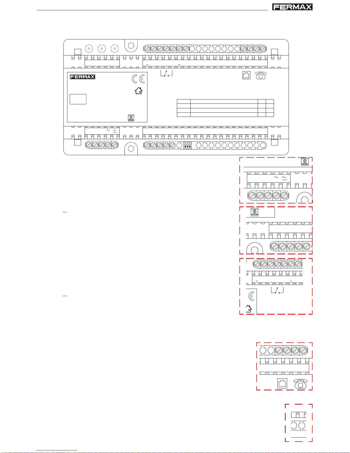
Connections and signage:
The interface has a DIN-10 box format (175 x 90 mm).
VDS
4+N
FORWARD OUT
FORWARD IN
ON
D
D
TF
TF
LN
LNNC
A
A
NO
C
USB
1 2 3
6
4
3
2
1
PRG
USE
PWR
L
-
+
1
SWITCH
PARÁMETRO / PARAMETER
ON OFF
2
3
SISTEMA / SYSTEM
4+N VDS
MODO / MODE
MCM SCM
ACCESO REMOTO / REMOTE ACCESS
OK NOK
INTERFACE TELEFÓNICO
TELEPHONE INTERFACE
REF: 4545
ON
321
Connectors:
• VDS:
+, -: 18Vdc Power supply.
L : Audio and VDS Dat a.
• 4+N:
~ : 12 V ac/Vdc power supply .
~ : 12 Vac power supply Common negative.
1 : Microphone polarisation / Door open activation.
2 : Audio output.
3 : Common negative
4 : Call Supports electronic call and buzzer.
6 : Input Audio
• Forward/ Auxiliary relay:
D, D : External forward activation input.
NC, C, NO : Auxiliary relay contacts. 2A-250V ac.
A: Negative.
A : Forward active output. Open collector, 100mA max.
Notes:
- The external forward activation input must be connected to an external contact (a
switch with no power).
- The Forward activation output must be connected to the coil of a relay or a led with
a current limiting resistance.
••
••
• Telephone lines:
LN, LN: Subscriber's external line.
TF, TF: Internal telephone line.
Notes:
- Polarity is free.
- The external line is not necessary for the interface to operate, nor for its configuration.
• Mini-USB connector: for configuring the interface from the PC.
VDS
L
-
+
4+N
6
4
3
2
1
FORWARD OUT
FORWARD IN
D
DNC
A
A
NO
C
TF
TF
LN
LN
USB
Page 6
Page 6
TELEPHONE INTERFTELEPHONE INTERF
TELEPHONE INTERFTELEPHONE INTERF
TELEPHONE INTERF
AA
AA
A
CECE
CECE
CE
TELEPHONE INTERFTELEPHONE INTERF
TELEPHONE INTERFTELEPHONE INTERF
TELEPHONE INTERF
AA
AA
A
CECE
CECE
CE
TECHNICAL FEA TURES
- Operating Temperature: -5ºC to +40ºC
- Relative Humidity: 5-90%, without condensation.
- Maximum consumption:
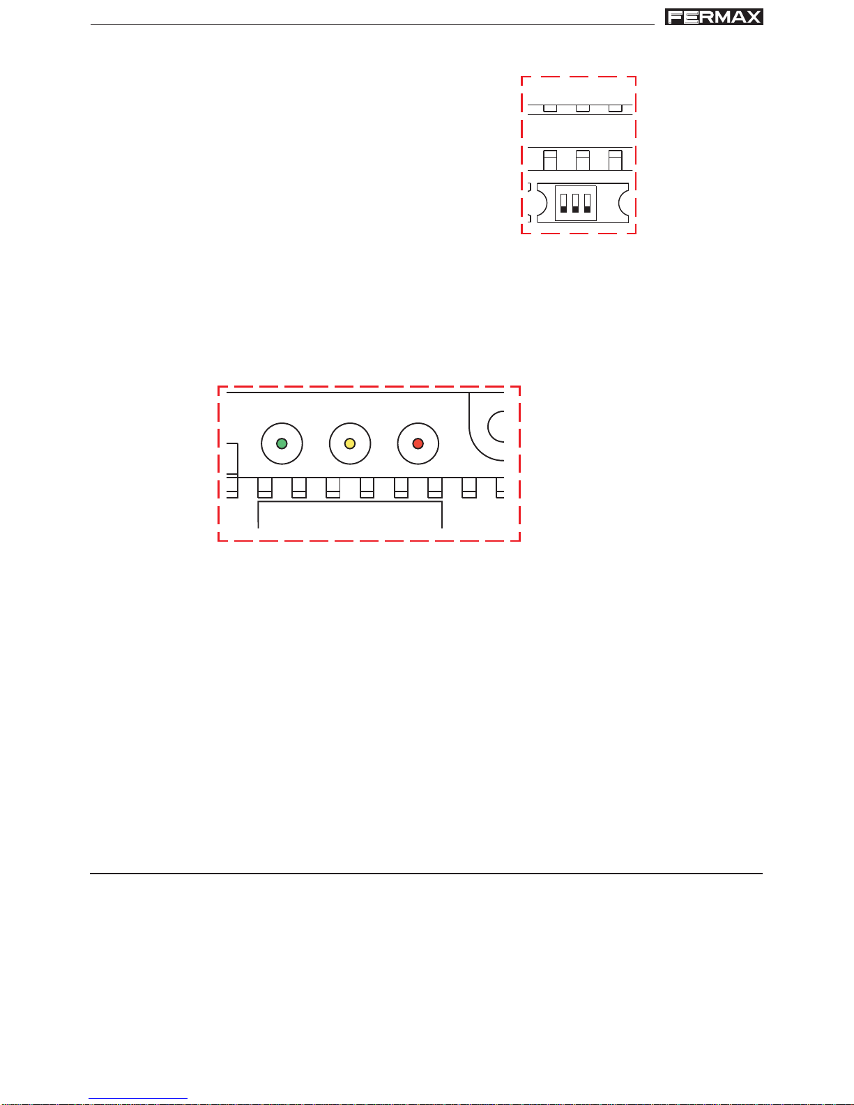
• 3 Dip-Switch: Device for configuring the operating mode.
System
Mode
Remote Access
1
2
3
Switch Parameters
4+N
MCM
OK
ON
VDS
SCM
NOK
OFF
Notes:
- SCM (Single Call Mode): Single Call. The interface acts as a telephone terminal that
responds to a single call from the street panels.
- MCM (Multi Call Mode): Multiple Call. Multi-call, that is, the connection between the
telephone interface and a telephone exchange or a telephone line for generating
calls to different extensions or telephones relative to the VDS calls generated on the
street panel.
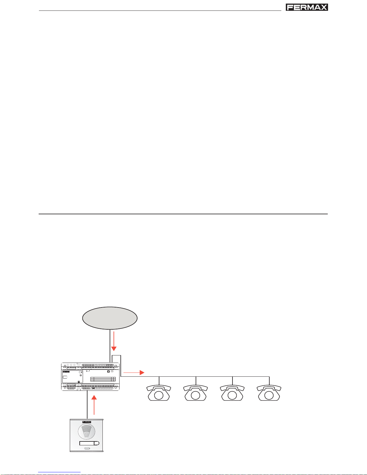
• 3 Leds:
LED Parameters OFF ON Flash
Red:
Green
Yellow
Power Supply
Active Audio.
Programming/
Forward
OFF
Audio OFF
No
Programming
ON
Audio ON
Programming
Convers/key pressed detection
Forward activated
Notes:
- The green and yellow combination alternatively flashing is used during the PC
connection via USB.
- When a key press is detected on the internal telephone, the green led flashes
continuously until it is hung up.
PRGUSE PWR
green yellow red
Standby
Maximum Consumption
60
400
125
470
55
220
Status Consumption depending on the power (mA)
12 Vac 12 Vdc 18 Vdc
ON
1 2 3
ON
321
Page 7

Page 7
TELEPHONE INTERFTELEPHONE INTERF
TELEPHONE INTERFTELEPHONE INTERF
TELEPHONE INTERF
AA
AA
A
CECE
CECE
CE
TELEPHONE INTERFTELEPHONE INTERF
TELEPHONE INTERFTELEPHONE INTERF
TELEPHONE INTERF
AA
AA
A
CECE
CECE
CE
- This must be installed on the interior, within an installations box.
- The telephone lines do not need to follow the polarity.
- In ADSL lines they must be connected after the right filter.
- On 4+N installations you can not share the street panel's power when AC. The VDS can
be powered by the bus.
- The telephones connected to the internal line must work with tone dialling.
Capacities and parameters description
The default values are displayed between brackets [ ] .
• Pin Code: only one, [0000]. This is used for accessing the remote site via the external
line.
• VDS Call num.: 001..199 [1] programmed. This is used in a single call (SCM) to
respond to the call from the street panel.
• Call forward numbers of a single call (SCM):
- Number: 2 (001-002).
- Length: 16 digits.
- [Not Defined].
• Call forward numbers of a multiple call (SCM):
- Number: 199 (001..199).
- Length: maximum of 16 digits (telephone numbers).
- [Not Defined].
• Door opening time (DOT / Door Opening Time): 01 .. 99" [04]. Time for the activation of the
4+N door open.
• Ring Call Time (RCT / Ring Call Time): 01..99" [30]. Maximum time that the interface waits
for the call from the street panel to be answered. In VDS, even if a time programmed
is greater than 30", the street panel will cut the call at this time.
• Divert Delay Time (DDT / Divert Delay Time): 01..99" [1]. The delay for the interior telephone
to respond to a call from the street panel before forwarding it to an external telephone.
Note: In VDS, this must be a maximum of 30" and less time than the duration of the
call (RCT).
• Auxiliary Relay Time (ART / Auxiliary Relay Time): 00..99" [08]. The time during which the
auxiliary relay remains activated. The value 00 means bi-stable mode.
• Conversation Time (CT / C onversation Time): 01..99" [90]. Conversation time. In VDS, the
conversation time must be set to 90 seconds to coincide with the VDS panel values.
Notes:
- For the interface to be operative after connecting the power, wait 10 seconds, which
is the time it needs to detect if there is an external telephone line, otherwise it generates
the power from the internal line.
- Call priorities: the call from the external telephone line always has priority. That is, if
you receive an external call and before hanging up you receive a call from the street
panel, the latter is not notified. On the other hand, if you are on a call from the street
panel, and you receive a call from the external line, the former is cancelled and the
latter is received.
Page 8
Page 8
TELEPHONE INTERFTELEPHONE INTERF
TELEPHONE INTERFTELEPHONE INTERF
TELEPHONE INTERF
AA
AA
A
CECE
CECE
CE
TELEPHONE INTERFTELEPHONE INTERF
TELEPHONE INTERFTELEPHONE INTERF
TELEPHONE INTERF
AA
AA
A
CECE
CECE
CE
• Ring cadence (RC / Ring Cadence): 1..9" [3]. Time interval between two consecutive call
tones when calling from a street panel.
• Conversation mode with the entry panel: [Full-Duplex (FD)]. Available audio modes: Full-
Duplex, Half-Duplex, Simplex.
• Conversation modes with forwarded calls: [Full-Duplex (FD)]. Available audio modes:
Full-Duplex, Half-Duplex, Simplex.
Notes:
Audio modes:
- Full Duplex (FD): The input audio channels (panel to telephone) and output audio
(telephone to panel) are opened simultaneously.
- Half Duplex (HD): The input and output audio channels are open, but only once
each, changing automatically from one function to another relative to the audio
level. The output channel has priority.
- Simplex (S): Only one audio channel is active each time. The switch is performed
manually. The output channel is open by default.
CONFIGURA TION
The Telephone Interface allows you to use the home phones to receive and answer calls
from the door intercom and you can also forward them externally via a telephone line.
Below are some examples with block diagrams.
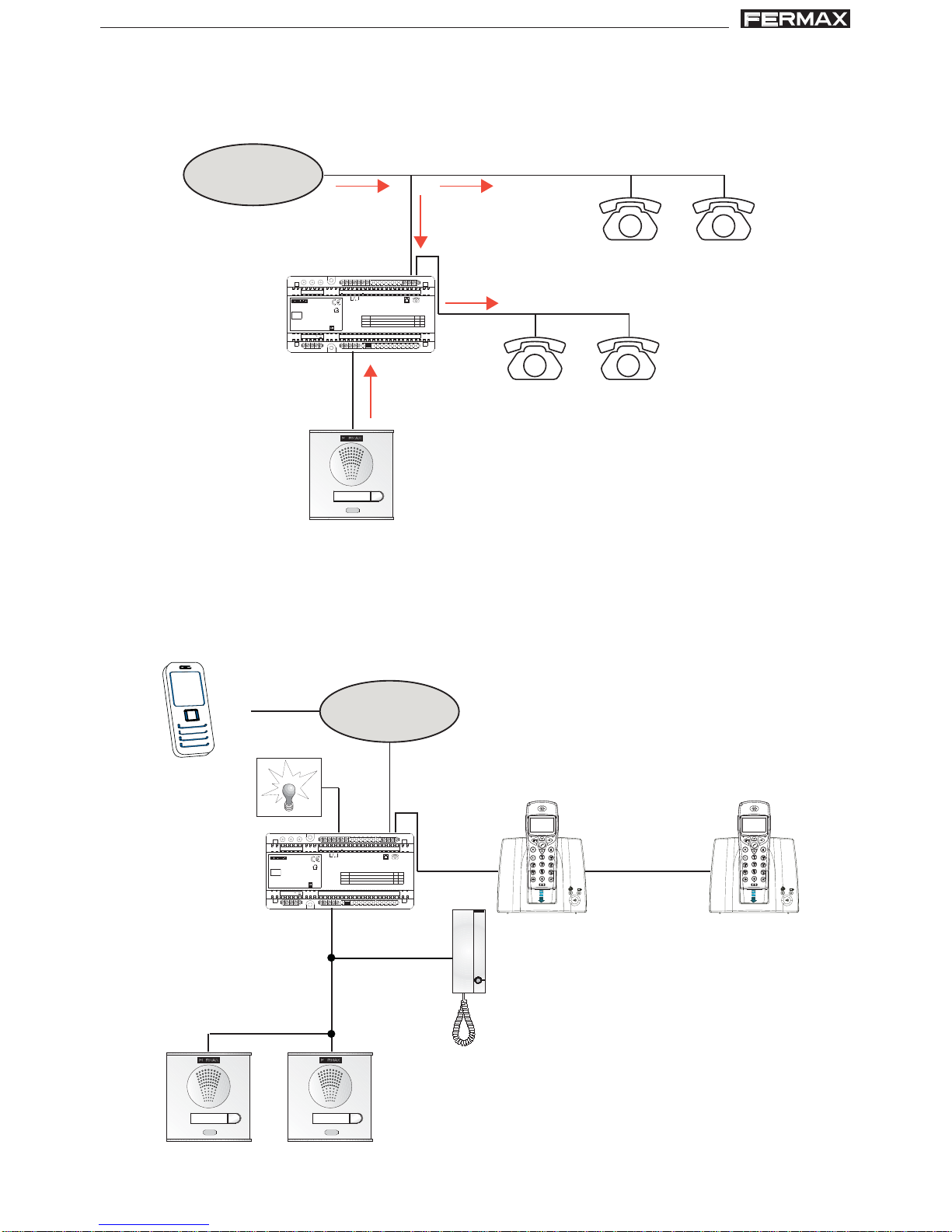
Configurations
o Typical
All of the telephones also perform electronic door entry system functions.
VDS
4+N
FORWARD OUT
FORWARD IN
ON
D
D
TFTFLN
LNNC
AANO
C
USB
1 2 3
643
2
1
PRG
USE
PWR
L
-
+
1
SWITCH
PARÁMETRO / PARAMETER
ON OFF
2
3
SISTEMA / SYSTEM
4+N VDS
MODO / MODE
MCMSCM
ACCESO REMOTO / REMOTE ACCESS
OK NOK
INTERFACE TELEFÓNICO
TELEPHONE INTERFACE
REF: 4545
ON
321
Telephone
Line
Internal line
Page 9
Page 9
TELEPHONE INTERFTELEPHONE INTERF
TELEPHONE INTERFTELEPHONE INTERF
TELEPHONE INTERF
AA
AA
A
CECE
CECE
CE
TELEPHONE INTERFTELEPHONE INTERF
TELEPHONE INTERFTELEPHONE INTERF
TELEPHONE INTERF
AA
AA
A
CECE
CECE
CE
o Single call (SCM)
VDS
4+N
FORWARD OUT
FORWARD IN
ON
D
D
TFTFLN
LNNC
AANO
C
USB
1 2 3
643
2
1
PRG
USE
PWR
L
-
+
1
SWITCH
PARÁMETRO / PARAMETER
ON OFF
2
3
SISTEMA / SYSTEM
4+N VDS
MODO / MODE
MCMSCM
ACCESO REMOTO / REMOTE ACCESS
OK NOK
INTERFACE TELEFÓNICO
TELEPHONE INTERFACE
REF: 4545
ON
321
4+N / VDS
Telephone
Line
Entry panels
Fermax telephone
External line
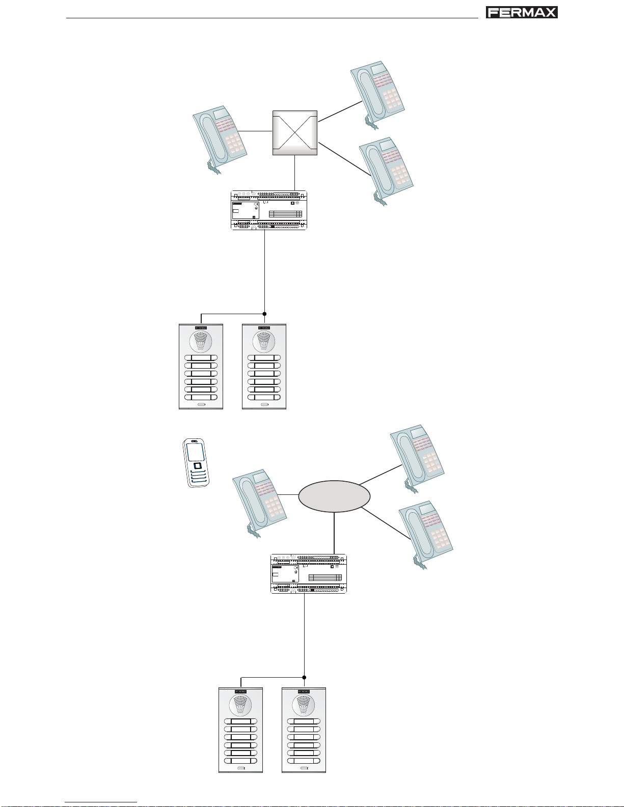
Operating Modes
o Mixed
In this example some telephones perform electronic door entry system functions and
others don’t.
VDS
4+N
FORWARD OUT
FORWARD IN
ON
D
D
TFTFLN
LNNC
AANO
C
USB
1 2 3
643
2
1
PRG
USE
PWR
L
-
+
1
SWITCH
PARÁMETRO / PARAMETER
ON OFF
2
3
SISTEMA / SYSTEM
4+N VDS
MODO / MODE
MCMSCM
ACCESO REMOTO / REMOTE ACCESS
OK NOK
INTERFACE TELEFÓNICO
TELEPHONE INTERFACE
REF: 4545
ON
321
Telephone
Line
telephone / door entry
only the telephone
Internal line
Internal line
Page 10
Page 10
TELEPHONE INTERFTELEPHONE INTERF
TELEPHONE INTERFTELEPHONE INTERF
TELEPHONE INTERF
AA
AA
A
CECE
CECE
CE
TELEPHONE INTERFTELEPHONE INTERF
TELEPHONE INTERFTELEPHONE INTERF
TELEPHONE INTERF
AA
AA
A
CECE
CECE
CE
o Multiple Call (MCM) with PABX (telephone switchboard)
PABX
1
2
4
3
5
6
7
8
9
*
0
#
A
B
1
2
4
3
5
6
7
8
9
*
0
#
A
B
1
2
4
3
5
6
7
8
9
*
0
#
A
B
VDS
4+N
FORWARD OUT
FORWARD IN
ON
D
D
TFTFLN
LNNC
AANO
C
USB
1 2 3
643
2
1
PRG
USE
PWR
L
-
+
1
SWITCH
PARÁMETRO / PARAMETER
ON OFF
2
3
SISTEMA / SYSTEM
4+N VDS
MODO / MODE
MCMSCM
ACCESO REMOTO / REMOTE ACCESS
OK NOK
INTERFACE TELEFÓNICO
TELEPHONE INTERFACE
REF: 4545
ON
321
VDS
Ext. 2
Ext. 3
Ext. 1
1
2
4
3
5
6
7
8
9
*
0
#
A
B
1
2
4
3
5
6
7
8
9
*
0
#
A
B
1
2
4
3
5
6
7
8
9
*
0
#
A
B
VDS
4+N
FORWARD OUT
FORWARD IN
ON
D
D
TFTFLN
LNNC
AANO
C
USB
1 2 3
643
2
1
PRG
USE
PWR
L
-
+
1
SWITCH
PARÁMETRO / PARAMETER
ON OFF
2
3
SISTEMA / SYSTEM
4+N VDS
MODO / MODE
MCMSCM
ACCESO REMOTO / REMOTE ACCESS
OK NOK
INTERFACE TELEFÓNICO
TELEPHONE INTERFACE
REF: 4545
ON
321
VDS
o Multiple Call (MCM) - External line
External
Line
Entry panels
Entry panels
Telephone
Network
External
Line
Telephone
switchboard
Page 11

Page 11
TELEPHONE INTERFTELEPHONE INTERF
TELEPHONE INTERFTELEPHONE INTERF
TELEPHONE INTERF
AA
AA
A
CECE
CECE
CE
TELEPHONE INTERFTELEPHONE INTERF
TELEPHONE INTERFTELEPHONE INTERF
TELEPHONE INTERF
AA
AA
A
CECE
CECE
CE
Notes:
- The telephone interface only accepts tone dialling.
- Use on ADSL lines:
•
You must install the right filters and perform the telephone installation as indicated on
the diagram.
•
If the installation is not installed as indicated, the modem tones may be heard through
the phones or during the forward.
IN
ADSL FILTER
FILTRO ADSL
OUT
VDS
4+N
FORWARD OUT
FORWARD IN
ON
D
D
TFTFLN
LNNC
AANO
C
USB
1 2 3
643
2
1
PRG
USE
PWR
L
-
+
1
SWITCH
PARÁMETRO / PARAMETER
ON OFF
2
3
SISTEMA / SYSTEM
4+N VDS
MODO / MODE
MCMSCM
ACCESO REMOTO / REMOTE ACCESS
OK NOK
INTERFACE TELEFÓNICO
TELEPHONE INTERFACE
REF: 4545
ON
321
ADSL
MODEM / ROUTER
PC
Telephone
Line
- The use in other non-conventional installations:
•
The Fermax telephone interface behaves the same way that a conventional analogic
telephone does, so it will work properly in any telephone installation in which you can
connect a telephone to, like those connected to conventional public networks.
- The use on telephone switchboards:
•
This interface may be incompatible with some types of telephone switchboards (ask
the switchboard manufacturer).
INST ALLA TION DIAGRAMS
In order to obtain optimal performance of the Telephone Interface and minimise external
interferences that may be produced (network noise, radio electric interferences... etc.) we
recommend:
- On 4+N installations you can not share the street panel's power when AC. The VDS can
be powered by the bus.
- The telephone pair and electronic entry panel cables transport audio signals that are
sensitive to interferences, so we recommend not placing it near noise made from motors
or industrial machinery or electric wiring.
Page 12

Page 12
TELEPHONE INTERFTELEPHONE INTERF
TELEPHONE INTERFTELEPHONE INTERF
TELEPHONE INTERF
AA
AA
A
CECE
CECE
CE
TELEPHONE INTERFTELEPHONE INTERF
TELEPHONE INTERFTELEPHONE INTERF
TELEPHONE INTERF
AA
AA
A
CECE
CECE
CE
o Installation diagrams - Conventional 4+N System
1
2
3
6
LINEA
EXTERNA
12364
VDS
4+N
FORWARD OUT
FORWARD IN
ON
D
D
TF
TF
LN
LNNC
A
A
NO
C
USB
1 2 3
6
4
3
2
1
PRG
USE
PWR
L
-
+
1
SWITCH
PARÁMETRO / PARAMETER
ON OFF
2
3
SISTEMA / SYSTEM
4+N VDS
MODO / MODE
MCM SCM
ACCESO REMOTO / REMOTE ACCESS
OK NOK
INTERFACE TELEFÓNICO
TELEPHONE INTERFACE
REF: 4545
ON
321
12 Vac
SEC. 12VacPRIM
Vac
1236
o BUILDING
forward switch (optional)
Call
Ex
EXTERNAL
LINE
Page 13

Page 13
TELEPHONE INTERFTELEPHONE INTERF
TELEPHONE INTERFTELEPHONE INTERF
TELEPHONE INTERF
AA
AA
A
CECE
CECE
CE
TELEPHONE INTERFTELEPHONE INTERF
TELEPHONE INTERFTELEPHONE INTERF
TELEPHONE INTERF
AA
AA
A
CECE
CECE
CE
o KIT
12 Vac
ELEKTRONISCHER VERSTÄRKER
AMPLIFICATEUR ELECTRONIQUE
ELECTRONIC AMPLIFIER
AMPLIFICADOR ELECTRONICO
POWER SUPPLY
ALIMENTACION
12 Vac/12 Vdc
NO
C
MIC
NO
C
~
CN2
12 Vac
Vac
SEC. 12VacPRIM
12 Vac
VARISTOR
1/N
JP1
LINEA
EXTERNA
VDS
4+N
FORWARD OUT
FORWARD IN
ON
D
D
TFTFLN
LNNC
AANO
C
USB
1 2 3
643
2
1
PRG
USE
PWR
L
-
+
1
SWITCH
PARÁMETRO / PARAMETER
ON OFF
2
3
SISTEMA / SYSTEM
4+N VDS
MODO / MODE
MCMSCM
ACCESO REMOTO / REMOTE ACCESS
OK NOK
INTERFACE TELEFÓNICO
TELEPHONE INTERFACE
REF: 4545
ON
321
Vac
SEC. 12VacPRIM
6
3
2
1
L+
L-
Cp
MDS
4+N
JP3
~
~
Cp
~
1236
4+N
MDS
JP2
1/N
JP1
forward switch
(optional)
EXTERNAL
LINE
Page 14

Page 14
TELEPHONE INTERFTELEPHONE INTERF
TELEPHONE INTERFTELEPHONE INTERF
TELEPHONE INTERF
AA
AA
A
CECE
CECE
CE
TELEPHONE INTERFTELEPHONE INTERF
TELEPHONE INTERFTELEPHONE INTERF
TELEPHONE INTERF
AA
AA
A
CECE
CECE
CE
o Installation diagrams - VDS System
o BUILDING
+
-
L
+
-
L
+L
-
Vac
18 Vdc
-+-+
PRIM SEC. 18Vdc220V
VDS
4+N
FORWARD OUT
FORWARD IN
ON
D
D
TF
TF
LN
LNNC
A
A
NO
C
USB
1 2 3
6
4
3
2
1
PRG
USE
PWR
L
-
+
1
SWITCH
PARÁMETRO / PARAMETER
ON OFF
2
3
SISTEMA / SYSTEM
4+N VDS
MODO / MODE
MCM SCM
ACCESO REMOTO / REMOTE ACCESS
OK NOK
INTERFACE TELEFÓNICO
TELEPHONE INTERFACE
REF: 4545
ON
321
LINEA
EXTERNA
forward switch (optional)
Page 15

Page 15
TELEPHONE INTERFTELEPHONE INTERF
TELEPHONE INTERFTELEPHONE INTERF
TELEPHONE INTERF
AA
AA
A
CECE
CECE
CE
TELEPHONE INTERFTELEPHONE INTERF
TELEPHONE INTERFTELEPHONE INTERF
TELEPHONE INTERF
AA
AA
A
CECE
CECE
CE
o KIT
12 Vac + 18 Vdc
12 Vac
-
L
+
Vac
B
D
A
C
E
ON
AUDIO
MIC
IDIOMA
LANGUAGE
NC
NO
AMPLIFICADOR - VERSTÄRKER
AMPLIFICATEUR - AMPLIFIER
JP2
DL2
CN7
MONITOR TEST
+-
18 Vdc
POWER SUPPLY
ALIMENTACION
JP2
C
MASTER
SLAVE
VDS
-
+
L
+12
C
-
S
NCNO
BS
EXIT
DC
18V
18 Vdc
12Vac
VARISTOR
LINEA
EXTERNA
DL2
VDS
4+N
FORWARD OUT
FORWARD IN
ON
D
D
TFTFLN
LNNC
AANO
C
USB
1 2 3
643
2
1
PRG
USE
PWR
L
-
+
1
SWITCH
PARÁMETRO / PARAMETER
ON OFF
2
3
SISTEMA / SYSTEM
4+N VDS
MODO / MODE
MCMSCM
ACCESO REMOTO / REMOTE ACCESS
OK NOK
INTERFACE TELEFÓNICO
TELEPHONE INTERFACE
REF: 4545
ON
321
230V
~
~
INPUT
230V ; 0,6 A
50-60 Hz
OUTPUT
18 V ; 1,5 A
~
OVERLOAD
ON
~~
~
12 V ; 1,5 A
forward switch
(optional)
EXTERNAL
LINE
Page 16

Page 16
TELEPHONE INTERFTELEPHONE INTERF
TELEPHONE INTERFTELEPHONE INTERF
TELEPHONE INTERF
AA
AA
A
CECE
CECE
CE
TELEPHONE INTERFTELEPHONE INTERF
TELEPHONE INTERFTELEPHONE INTERF
TELEPHONE INTERF
AA
AA
A
CECE
CECE
CE
Installation in a DIN rail
Fastened with screws
+18V 1.5A
5
0
6
0
H
z
.
5
0
V
A
M
A
X
.
12V 1A
FUE
N
TE ALIM
EN
TA
CIO
N
KIT DIGITAL
M
A
D
E
IN
S
P
A
I
N
Disassembly
Assembly
INTERFACE INST ALLA TION
USER OPERATION
Quick Guide
o The available options in Standby mode (upon hanging up the telephone) are the following:
Key Option
0...9 Dial a number for external communication
* 1 Communication with panel 1 (VDS) or default panel (4+N)
* 2 Communication with panel 2 (VDS)
* 4 Call to reception.
* 7 Auxiliary Relay Activation during the auxiliary relay time (ART)
* 8 Auxiliary Relay Deactivation
* # N Internal Communication (N=1...4)
# # # 7 # Forward ON
# # # 8 # Forward OFF
# # # Programming Access Mode, (page 32)
o The available options in Remote mode are the same as in Standby mode, besides upon
the completion of remote mode:
Key Option
# End of remote mode
Page 17

Page 17
TELEPHONE INTERFTELEPHONE INTERF
TELEPHONE INTERFTELEPHONE INTERF
TELEPHONE INTERF
AA
AA
A
CECE
CECE
CE
TELEPHONE INTERFTELEPHONE INTERF
TELEPHONE INTERFTELEPHONE INTERF
TELEPHONE INTERF
AA
AA
A
CECE
CECE
CE
o The options available during the Conversation (status: communication with the entry
panel):
Key Option
5 Activation of the door open relay during the door open time (DOT)
7 Auxiliary Relay Activation during the auxiliary relay time (ART)
8 Auxiliary Relay Deactivation
1** Half-Duplex Mode. See note***
2** Full-Duplex Mode. See note***
0** Simplex Mode
0 Channel switch
See note***
3 Increase Upload Audio (one step). See note*
6 Decrease Upload Audio (one step). See note*
4 Call waiting. Resume the conversation. See note****
* Start conversation. See note**
# End of conversation. See note**
Notes:
- * This setting is not stored.
- ** These keys are used exclusively during a forward or in MCM mode if the interface can
not detect the answering/hanging-up of the telephone. Upon receiving the call if you
hear: beep beep beep, press * to answer and # to end (hang-up) the conversation.
- *** The last mode selected duplex / simplex is stored for the following communications
(different from the CONVERSATION status with the panel). We recommend using the
Half-Duplex mode for forwarding since it allows for a greater volume both of the input
and output without it coupling.
- **** If the entry panel stays in standby, when receiving an external call and it hangs up
before recuperating the connection with the entry panel, it can not be recuperated since
the system returns to standby.
Forward activation. Steps (from the programming menu):
1. Accessing Programming mode: pick up the telephone and before 3 seconds pass,
press # # #, confirming access to programming mode via a confirmation tone: beepbeep-beep. (If already in this mode this step is not necessary).
2. Press the 7 key, you hear a beep.
3. Press the # key, you hear a beep, return to the configuration menu.
Sequence completed: # # # (beep-beep-beep) 7 (beep) # (beep)
o The available options for the user via the Programming menu are as follows:
Forward deactivation Steps (from the programming menu):
1. Accessing Programming mode: pick up the telephone and before 3 seconds pass,
press # # #, confirming access to programming mode via a confirmation tone: beepbeep-beep. (If already in this mode this step is not necessary).
2. Press the 8 key, you hear a beep.
3. Press the # key, you hear a beep, return to the configuration menu.
Sequence completed: # # # (beep-beep-beep) 8 (beep) # (beep)
o Remote connection see page 21.
Page 18

Page 18
TELEPHONE INTERFTELEPHONE INTERF
TELEPHONE INTERFTELEPHONE INTERF
TELEPHONE INTERF
AA
AA
A
CECE
CECE
CE
TELEPHONE INTERFTELEPHONE INTERF
TELEPHONE INTERFTELEPHONE INTERF
TELEPHONE INTERF
AA
AA
A
CECE
CECE
CE
Description of functions
• Standby.
Default status. See the available options for Standby mode in the quick guide.
Notes on some of the functions of the quick guide:
- On the call to the VDS Reception you must hang up the phone after dialling *4 in order
to receive this call.
- In the programming access you use the # key and on the other functions you use the
* key in combination with a number, so you must know that there is a time limit of 3
seconds after picking-up the phone during which the * and # tone do not transmit via
the abandoned line in order to avoid conflicts with the special functions reserved for
the telephone company or special telephone numbers (bank, etc...). If you want to
use these keys, in order to use the commands on the interface you must press * or #
before this time. This time limit is refreshed every time you press a * or #.
• Reception of the call from the entry panel as a single call (SCM).
If you receive a call from the entry panel, the interface will act as an electronic door
entry system telephone, responding to a single call, performed on the call line (4 + N)
or through the programmed call code (VDS). The ring tone is generated in all interior
telephones.
- if one of the interior telephones answers within the ring call time (RCT), it then
communicates with the panel,
- but if the ring call time (RCT) runs out without a response, then the generation of the
call is stopped and it returns to standby.
- if the Fermax telephone responds to the call during the ring call time (RCT) before
the internal telephones, then the the interface stops calling and returns to standby
(only VDS).
The call tone can be changed to distinguish it from the external call via the programming
menu, see programming Ring Cadence (RC / Ring Cadence). During the conversation
you can open the entrance door, activate an auxiliary relay, adjust the upload audio
level or the duplex conversation mode.
The conversation ends when the telephone hangs up, after the programmed
conversation time or when the exterior panel cuts the conversation (what happens
first).
If during the creation of a ring tone from the entry panel an external call occurs, this
would have priority and generate the corresponding ring tone so that upon picking up
the internal telephone the communication is established with the external line.
• Reception of an external call.
If you receive an external call, (this call is generated by the telephone company when
an external telephone calls), all interior telephones will produce the call tone and one
of them will respond, establishing the normal communication as if there is no interface.
The ring tone is generated by the telephone switchboard or the phone itself (depending
on the models). This function ends when the telephone that responds to the call
hangs-up.
Page 19

Page 19
TELEPHONE INTERFTELEPHONE INTERF
TELEPHONE INTERFTELEPHONE INTERF
TELEPHONE INTERF
AA
AA
A
CECE
CECE
CE
TELEPHONE INTERFTELEPHONE INTERF
TELEPHONE INTERFTELEPHONE INTERF
TELEPHONE INTERF
AA
AA
A
CECE
CECE
CE
Key Option
* 1 Communication with panel 1 (VDS) or default panel (4+N)
* 2 Communication with panel 2 (VDS)
• Connection with the entry panel.
You can connect from one of the interior telephones to one of the exterior panels
without requiring a previous call, simply by pressing two keys (* N).
If during the external call a call is made from the entry panel, the following occurs:
- If the entry panel calls before picking up the phone, it will not be answered and you
will lose the call (the external call has priority).
- If the entry panel calls during the conversation, it is monitored and you can answer it.
See Call waiting.
If you do not answer the call within the ring call time (RCT) and switch 3 is in ON, the
call is attended to via the interface, which requests the PIN code via a special sound.
If the PIN code is correct the interface will go to remote connection status, but if it is
incorrect, the interface will cancel communication. In the Quick guide see the available
options in Remote
mode.
• Communication with the entry panel.
This is the status corresponding to communication between the entry panel and the
interior telephone. During this status audio is established in full-duplex (default), but
you can change it to a different mode (half-duplex or simplex). The different audio
modes are as follows:
- Full Duplex (FD): The upload audio channels (panel to telephone ) and download
audio (telephone to panel) are open simultaneously.
- Half Duplex (HD): The input and output audio channels are open, but only once
each, changing automatically from one function to another relative to the audio
level. The download channel has priority.
- Simplex (S): Only one audio channel is active each time. The switch is done manually
by pressing the 0 key. The download channel is open by default.
You can also adjust the audio level for the upload channel. See the Quick guide for the
options available during the Conversation (status: communication with the entry
panel).
If in communication with the panel you receive an external call, you will hear a special
tone on the interior telephone (two repeated short tones every 5 seconds). The user
can leave the current conversation on hold and attend to the external line and then
resume the conversation with the entry panel. See Call waiting.
See the Quick Guide for the available options during the Conversation (status:
communication with the entry panel)
This function is useful when a previous conversation has expired and the user wants
to recuperate it, or simply to open the door. Once connected, the available options are
described in the Quick guide: The options available during the Conversation (status:
communication with the entry panel).
Page 20

Page 20
TELEPHONE INTERFTELEPHONE INTERF
TELEPHONE INTERFTELEPHONE INTERF
TELEPHONE INTERF
AA
AA
A
CECE
CECE
CE
TELEPHONE INTERFTELEPHONE INTERF
TELEPHONE INTERFTELEPHONE INTERF
TELEPHONE INTERF
AA
AA
A
CECE
CECE
CE
• Internal Communication (intercommunication).
When there are various internal telephones (maximum 4), you can call from one to
another simply by generating a series of ring tones like that of number N (1...4). This
tone is different from the external line call or the entry panel call. Both the telephone
that started the call and the telephone being called must pick-up the phone and then
start a conversation. The programmed conversation time is also limited as well as
when both phones hang-up.
Key Option
* # N Internal communication,
(after dialling you must hang up to generate the N tones).
• Forwarding to an external telephone as a single call (SCM)
If the call from the entrance door is not answered by an interior telephone within the
programmed time, and the forward mode is selected, then the call is transferred to
the programmed external telephone.
The receptor will respond to the call and has the option of conversing, opening the
entrance door , adjusting the audio level or activating an auxiliary relay. Y ou might need
to use special keys to notify the interface that you have hung-up and to hang up in case
that the interface does not recognise these actions. Upon receiving the call if you
hear: beep beep beep, press * to answer and # to end (hang-up) the conversation.
You can program a second telephone number if the first one does not respond to the
call within the programmed time.
In this mode, the available options are described in the Quick guide: Options available
in Conversation mode.
The forward mode is activated from an option on the programming menu or with the
switch connected to the interface. This is supervised via a LED and an output terminal.
For more details on this function see: Key 3 - Forward telephone numbers directory
in Single Call (SCM) and Multiple Call (MCM)
• Generating multiple calls (MCM).
For VDS installations, the interface can manage various calls (up to 199), which
generates different call numbers relative to a programmed table. In this mode you
can call different extensions of a switchboard by connecting an internal line to an
interface's external line, like for an office, so the visitor can select the person who will
receive the call. You can also generate external calls if the subscriber's telephone line
is connected to the external line's connector.
This is a specific case of the telephone system where you connect the entry panel to
the telephone line (through the interface) and the calls are received by the apartments'
individual telephones, which use a company's telephone service.
In this mode, the telephone called has the available options as those described in the
Quick guide: Options available in Conversation mode.
You can forward the calls to a specific extension for a period of time just by activating
the forward mode (sería la dirección VDS grabada en el interface. This is useful when
there is a receptionist that has to filter all of the calls during working hours, but
afterwards the calls must be passed directly to their respective extensions. The
telephone to which it is forwarded to depends on the position in the directory , indicated
in option 0 of the configuration menu.
For more details on this function see: Key 3 - Forward telephone numbers directory
in Single Call (SCM) and Multiple Call (MCM)
Page 21

Page 21
TELEPHONE INTERFTELEPHONE INTERF
TELEPHONE INTERFTELEPHONE INTERF
TELEPHONE INTERF
AA
AA
A
CECE
CECE
CE
TELEPHONE INTERFTELEPHONE INTERF
TELEPHONE INTERFTELEPHONE INTERF
TELEPHONE INTERF
AA
AA
A
CECE
CECE
CE
• Auxiliary Relay Activation.
You can activate (or deactivate) an auxiliary relay at any time via a simple pressing of
a key, from different telephones: Internal or External and situations: during the
conversation or in standby.
The relay has a programmed time for it to automatically turn off after activation, except
when programmed as bi-stable (time= 00).
o In Standbyor Remote mode.
Key Option
* 7 Auxiliary Relay Activation during the auxiliary relay time (AR T)
* 8 Auxiliary Relay Deactivation
o During the Conversation (status: communication with the entry panel).
Key Option
7 Auxiliary Relay Activation during the auxiliary relay time (AR T)
8 Auxiliary Relay Deactivation
• Call to reception.
You can call the reception in standby mode by only pressing a couple of keys from the
internal telephones.
Key Option
* 4 Call to VDS reception.
• Call waiting.
When an interior telephone and entry panel or external line are in communication, or
when two internal telephones are in process and there is a call entering from another
device (entry panel), a special ring tone sounds and you can temporarily hold the
current conversation to attend to the incoming call and then resume the previous call.
Key Option
4 Call waiting. Resume the conversation. See note.
Notice:
- If the entry panel stays in standby, when receiving an external call and it hangs up
before recuperating the connection with the entry panel, it can not be recuperated
since the system returns to standby.
• Accessing Programming.
You can access the programming menu from the interior telephone to configure all of
the internal parameters. See PROGRAMMING: ACCESS - OPTIONS or QUICK
PROGRAMMING GUIDE.
• Remote Connection.
You can connect remotely to the interface from an external telephone (if the external
line's terminal is connected to the external telephone line), from a telephone switch
extension (if the external line's terminal is connected to a switchboard extension) in
order to access all of the functions. The remote telephone or extensions must mark
the number of the line in which the interface is connected and wait the maximum
calling time. The interface will generate the call in the internal telephones and if
Page 22

Page 22
TELEPHONE INTERFTELEPHONE INTERF
TELEPHONE INTERFTELEPHONE INTERF
TELEPHONE INTERF
AA
AA
A
CECE
CECE
CE
TELEPHONE INTERFTELEPHONE INTERF
TELEPHONE INTERFTELEPHONE INTERF
TELEPHONE INTERF
AA
AA
A
CECE
CECE
CE
PROGRAMMING: ACCESS - OPTIONS.
You can access the programming mode from the interior telephone to configure all of the
available options.
Accessing Programming mode:pick up the telephone and before 3 seconds pass, press
# # #, confirming access to programming mode via a confirmation tone: beep-beep-beep.
The programming mode ends and returns to standby if no key is pressed for 30 seconds
or when you hang up the telephone or press the # key (whatever action occurs first).
Notice:
- You can access programming mode from the FORWARD, STANDBY, or MCM statuses
via an internal telephone (without a PIN) or from a remote telephone (with a PIN).
The options available are:
Key Option
0 VDS interface Address (SCM) (001...199) [1] (programmed)
1 PIN (0000...9999) [0000]
2 No function
3 Telephone numbers directory in Single Call (SCM) and Multiple Call (MCM)
4 Timers
5 No function
6 Call tone cadence (1..9)”. [3]
7 Forward activation.
8 Forward deactivation.
9 Audio Adjustments
# Exit
there is no response after the ring tone configured time, the interface responds
with a special sound (4 beeps) asking for a PIN. If correct, all functions are available
as with the internal telephone: programming, connection to the street panel, door
open, activating the auxiliary relay....etc.
This connection is protected by a switch that activates / deactivates this function.
This function is useful when the administrator of the installation wants to modify
some parameter to avoid having to go to the location (for example: change the call
number) or activate the auxiliary relay remotely (for example: turning your heating on in
a second residence). For more details on this function see: Key 1 - PIN (0000...9999)
[0000] and Key 3 - Forward telephone numbers directory in Single Call (SCM) and
Multiple Call (MCM).
• Programming via PC.
Since in some cases you must program a lot of information (like with the directory),
we recommend using a PC to configure the parameters. The PC can be connected
via the mini-USB interface and a proprietary software. The software is available at
www.fermax.com.
Notes:
- The default values are displayed between brackets [ ] for the different options.
- Confirmation tones:
* Correct (OK): Beep-beep
* Incorrect (Not OK): Beep-bop
Page 23

Page 23
TELEPHONE INTERFTELEPHONE INTERF
TELEPHONE INTERFTELEPHONE INTERF
TELEPHONE INTERF
AA
AA
A
CECE
CECE
CE
TELEPHONE INTERFTELEPHONE INTERF
TELEPHONE INTERFTELEPHONE INTERF
TELEPHONE INTERF
AA
AA
A
CECE
CECE
CE
RESETTING Parameters: To reset parameters to default values, in the programming
menu, press the following key sequence: *000#.
o Key 0 - VDS interface address (SCM)
• VDS call num.: This is used in a single call (SCM) to respond to the call from the
exterior panel. Possible programmable values 001...199 [250] (not programmed).
Steps:
1. Accessing Programming mode: pick up the telephone and before 3 seconds pass,
press # # #, confirming access to programming mode via a confirmation tone: beepbeep-beep. (If already in this mode this step is not necessary).
2. Press the 0 key, you hear a beep.
3. Press VDS call number (3 digits), for example: 001,
a) you hear: A confirmation beep will be emitted.
b) and automatically you hear: beep-beep of the correctly entered data, (if incorrect
you hear: Beep-bop)
c) you hear beep-beep-beep, return to the configuration menu.
Sequence completed: # # # (beep-beep-beep) 0 (beep) 001 (beep-beep)(beep-beep-beep)
o Key 1 - PIN (0000...9999) [0000]
• Pin: This is used for accessing the remote site via the external audio line from the
telephone. Programming a single pin. The default Programming Code is 0000.
Steps:
1. Accessing Programming mode: pick up the telephone and before 3 seconds pass,
press # # #, confirming access to the programming mode via a confirmation tone:
beep-beep-beep. (If already in this mode this step is not necessary).
2. Press the 1 key, you hear a beep.
3. Enter a new pin (if you want to change) for example: 2233,
a) you hear: a confirmation beep will be emitted.
b) and automatically you hear: beep-beep of the correctly entered data, (if incorrect
you hear: Beep-bop)
c) you hear beep-beep-beep, return to the configuration menu.
Sequence completed: # # # (beep-beep-beep) 1 (beep) 2233 (beep)(beep-beep)(beep-
beep-beep)
Related function: Remote Access.
Description options.
• 3 Dip-Switch: Device for configuring the operating mode.
Remote Access3
Switch Parameters
OK
(allowed)
ON
NOK
(not allowed)
OFF
Remote Access.
You can connect remotely to the interface from an external telephone (if the external
line’s terminal is connected to the external telephone line), from a telephone switch
extension P ABX (if the external line's terminal is connected to a P ABX extension) in order
to access all of the functions.
Steps:
1. The remote telephone or extensions must dial the number of the line in which the
interface is connected and wait the maximum calling time.
Page 24

Page 24
TELEPHONE INTERFTELEPHONE INTERF
TELEPHONE INTERFTELEPHONE INTERF
TELEPHONE INTERF
AA
AA
A
CECE
CECE
CE
TELEPHONE INTERFTELEPHONE INTERF
TELEPHONE INTERFTELEPHONE INTERF
TELEPHONE INTERF
AA
AA
A
CECE
CECE
CE
2. The interface will generate the call on the internal telephones and if there is no
response after the ring tone configured time, the interface responds with a special
sound asking for a PIN.
3. If you enter the pin correctly, the interface will generate the confirmation tone (beepbeep) and all functions are available like with the internal telephone: programming,
connection to the street panel, door open, activating the auxiliary relay....etc.
o Key 3 - Forward telephone numbers directory in Single Call (SCM) and Multiple Call
(MCM)
The interface accepts different configurations and working modes. These are the available
modes:
o In Single Call Mode (SCM) - (4+N and VDS Systems): The forward is made (if activated)
and it is not answered from the internal phone, the first directory number. It it also isn't
answered, the second number in the directory is attempted.
o In Multiple Call Mode (SCM) - (VDS Systems): The interface converts the calls from
the entry panel to telephone numbers via the directory, that is a multi-call. For calls
generated from the entry panel (VDS), the telephone interface generates different
extensions or telephones.
Notes:
- You can access this mode in any status FORWARD, STANDBY or MCM.
- This mode is only accessible if switch 3 is ON for security reasons.
-This function is useful when the administrator of the installation wants to modify some
parameter to avoid having to go to the location (for example: change the call number) or
activate the auxiliary relay remotely (for example: turning your heating on in a second
residence).
The available options are:
Key Option
* 1 Communication with panel 1 (VDS) or the default panel (4+N)
* 2 Communication with panel 2 (VDS)
* 7 Auxiliary Relay Activation during the auxiliary relay time (ART)
* 8 Auxiliary Relay Deactivation
# # #Accessing Programming Mode
# End of remote mode
Notes:
- The communication with the entry panel operates the same way as in the call forward,
with the same options being accessible.
- Once an option is selected, you can not select other options, except for the activation and
deactivation of the auxiliary relay.
-This status ends and returns to standby if no key is pressed for 30 seconds or when you
hang up the telephone or press the # key (whatever action occurs first).
Page 25

Page 25
TELEPHONE INTERFTELEPHONE INTERF
TELEPHONE INTERFTELEPHONE INTERF
TELEPHONE INTERF
AA
AA
A
CECE
CECE
CE
TELEPHONE INTERFTELEPHONE INTERF
TELEPHONE INTERFTELEPHONE INTERF
TELEPHONE INTERF
AA
AA
A
CECE
CECE
CE
Steps for creating the forward phone directory:
1. Accessing Programming mode: pick up the telephone and before 3 seconds pass,
press # # #, confirming access to programming mode via a confirmation tone: beepbeep-beep. (If already in this mode this step is not necessary).
2. Press the 3 key, you hear a beep.
3a)Enter a new telephone number:
a) Enter the position of the directory: 4+N / VDS SCM (001-002) / VDS MCM (001...199).
Enter 3 digits. For example: 002. You hear: a confirmation beep will sound,
b) Enter a new telephone number. Maximum 16 digits (0...9). To enter a pause, use
# (for a telephone switchboard). For example, enter the telephone number: 605
812 339. You hear: a confirmation beep will be emitted,
c) Press* you hear: beep-beep of the correctly entered data, (if incorrect you hear:
Beep-bop).
Notice: If more than one number is going to be entered in the directory, you don't
have to exit back to the main menu every time. After * enter the next position in the
directory.
d) Press #, you hear beep-beep-beep, return to the configuration menu.
Sequence completed: # # # (beep-beep-beep) 3 (beep) 002 (beep) 605 812 339 (beep) *
(beep-beep) # (beep-beep-beep)
3b) Deleting a telephone number:
a) Enter the VDS Address (001...199) ¡. For example: 002. You hear: a confirmation
beep will be emitted,
b) Press* you hear: beep-beep of the correctly entered data, (if incorrect you hear:
Beep-bop)
c) Press #, you hear beep-beep-beep, return to the configuration menu.
Sequence completed: # # # (beep-beep-beep) 3 (beep) 002 (beep) * (beep-beep) #
(beep-beep-beep)
VDS Address Telephone number
001 0 # # 619 333 258
002 0 # # 620 342 255
003 0 # # 620 375 214
004 0 # # 627 545 302
00 5 1212
00 6 2715
00 7 2321
. . . . . .
19 9 2635
• 3 Dip-Switch: Device for configuring the operating mode.
Notice:
- In this status, the interior telephones are not operative, except for receiving external
calls and for programming.
- In this mode you can not connect Fermax telephones to the installation.
- Upon receiving the call if you hear: beep beep beep, press * to answer and # to
end (hang-up) the conversation.
Mode2
Switch
Parameters
MCM
ON
SCM
OFF
Page 26

Page 26
TELEPHONE INTERFTELEPHONE INTERF
TELEPHONE INTERFTELEPHONE INTERF
TELEPHONE INTERF
AA
AA
A
CECE
CECE
CE
TELEPHONE INTERFTELEPHONE INTERF
TELEPHONE INTERFTELEPHONE INTERF
TELEPHONE INTERF
AA
AA
A
CECE
CECE
CE
Notes:
- When you forward the call the conversation time is reset (CT), both for the first and
second forwarded telephone in order to avoid that the conversation time is insufficient.
- Due to factors concerning the detection of the hang-up, some telephone lines' hang-ups
(switchboard lines) are not detected on the forwarded telephone since the line's polarity
doesn't change. For this reason the interface sounds a repetitive beep to alert the
receiver that they must press the * key to notify of the hang-up. If the interface detects
the hang-up, this tone stops.
When the forwarded telephone answers the call, the interface automatically connects
the entry panel to the telephone line. The VDS line is not connected until then to allow
the other Fermax telephones in parallel to the interface to ring and have the chance of
answering the call.
Related function: Forward.
Forwarding to an external telephone
You access this status when the forward terminals not on line or when it is activated
from the programming menu with the 7 option, (see Forward Activation for more
information). The yellow led lights up and flashes to indicate that it the forward is activated.
D, D : External forward activation input. Current Free
Contact
WARD IN
D
DNC
PRG
USE
PWR
INTERFACE TELEFÓNICO
TELEPHONE INTERFACE
Steps for activating the forward from the programming menu:
1. Accessing Programming mode: pick up the telephone and before 3 seconds pass,
press # # #, confirming access to programming mode via a confirmation tone: beepbeep-beep. (If already in this mode this step is not necessary).
2. Press the 7 key, you hear a beep.
3. Press the # key, you hear a beep, return to the configuration menu.
Sequence completed: # # # (beep-beep-beep) 7 (beep) # (beep)
The forward status is identical to the standby status, with the difference that if you
receive a call from the exterior panel and do not answer the interior telephone for the
divert delay time (DDT), then the call is forwarded to the pre-programmed telephone
001. If the telephone does not answer within the ring call time (RCT), or simply cancels
the call, if a second telephone 002 is programmed (SCM function), it is forwarded to. If
the second telephone doesn't respond either, then the interface returns to the standby
mode.
The receiver will respond to the call and has the option of conversing, opening the
entrance door, adjusting the audio level or activating an auxiliary relay.
Page 27

Page 27
TELEPHONE INTERFTELEPHONE INTERF
TELEPHONE INTERFTELEPHONE INTERF
TELEPHONE INTERF
AA
AA
A
CECE
CECE
CE
TELEPHONE INTERFTELEPHONE INTERF
TELEPHONE INTERFTELEPHONE INTERF
TELEPHONE INTERF
AA
AA
A
CECE
CECE
CE
During the conversation the led remains green. The options are similar to the
communication with the entry panel status:
Key Option
5 Activation of the door-open relay during the door open time (DOT)
7 Auxiliary Relay Activation during the auxiliary relay time (ART)
8 Auxiliary Relay Deactivation
1** Half-Duplex Mode. See note***
2** Full-Duplex Mode. See note***
0** Simplex Mode
0 Channel switch
See note***
3 Increase Upload Audio (one step). See note*
6 Decrease Upload Audio (one step). See note*
* Start conversation. See note**
# End of conversation. See note**
Notes:
- * This setting is not stored.
- ** These keys are used exclusively during a forward or in MCM mode if the interface can
not detect the answering/hanging-up of the telephone. Upon receiving the call if you
hear: beep beep beep, press * to answer and # to end (hang-up) the conversation.
- *** The last mode selected duplex / simplex is stored for the following communications
(different from the CONVERSATION with the panel status). We recommend using the
Half-Duplex mode for forwarding since it allows for a greater volume both of the input
and output without it coupling.
The communication ends when:
- Concluding conversation time (CT).
- The remote telephone hangs-up or presses #.
- The entry panel is reset (VDS), for longer than 90 seconds or a call to another
home.
The forward status changes to STANDBY when the forward terminals are opened or it is
deactivated in the programming menu.
Steps for deactivating the forward from the programming menu:
1. Accessing Programming mode: pick up the telephone and before 3 seconds pass,
press # # #, confirming access to programming mode via a confirmation tone: beepbeep-beep. (If already in this mode this step is not necessary).
2. Press the 8 key, you hear a beep.
3. Press the # key, you hear a beep, return to the configuration menu.
Sequence completed: # # # (beep-beep-beep) 8 (beep) # (beep)
Notice:
- The audio level settings must be made keeping in mind the call forward, since this is the
least favourable case. If the audio levels are too unbalanced relative to the conversation
with the interior telephone, in order to avoid that it is not heard well, use the half-duplex
mode during forwards, which allows for a considerable increase of the levels without
coupling.
Page 28

Page 28
TELEPHONE INTERFTELEPHONE INTERF
TELEPHONE INTERFTELEPHONE INTERF
TELEPHONE INTERF
AA
AA
A
CECE
CECE
CE
TELEPHONE INTERFTELEPHONE INTERF
TELEPHONE INTERFTELEPHONE INTERF
TELEPHONE INTERF
AA
AA
A
CECE
CECE
CE
o Key 4 - Timers
The different times that can be programmed with other different values to that
programmed by default are:
• Ring Call Time (RCT / Ring Call Time): 01..99" [30]. Maximum time that the interface waits
for the call from the street panel to be answered. In VDS, even if a time programmed
is greater than 30", the street panel will cut the call at this time.
• Door opening time (DOT / Door Opening Time): 01 .. 99" [04]. Time for the activation of the
4+N door open.
• Conversation Time (CT / Conversation Time): 01..99" [90]. Conversation time. In VDS, the
conversation time must be set to 90 seconds to coincide with the VDS panel values.
• Divert Delay Time (DDT / Divert Delay Time): 01..99" [1]. The delay for the interior telephone
to respond to a call from the street panel before forwarding it to an external telephone.
Note: In VDS, this must be a maximum of 30" and less time than the duration of the
call (RCT).
• Auxiliary Relay Time (ART / Auxiliary Relay Time): 00..99" [08]. The time during which the
auxiliary relay remains activated. The value 00 means bi-stable mode.
Steps:
1. Accessing Programming mode: pick up the telephone and before 3 seconds pass,
press # # #, confirming access to programming mode via a confirmation tone: beepbeep-beep. (If already in this mode this step is not necessary).
2. Press the 4 key, you hear a beep.
3. Enter the desired parameter value, values: 1...5 (1 digit). for example: 2 (door open
activation time),
a) you hear: a confirmation beep will sound,
b) the time value, values: 00...99 (2 digits), for example: 08 (for 8 seconds),
c) and automatically you hear: beep-beep of the correctly entered data, (if incorrect
you hear: Beep-bop)
d) you hear beep-beep-beep, return to the configuration menu.
Sequence completed: # # # (Beep-Beep-Beep) 4 (Beep) 2 (Beep) 08 (Beep-Beep)
(Beep-Beep-Beep)
The available options are:
Key Parameter
1 Ring Call Time (RCT / Ring Call Time)
2 Door Opening Time (DOT / Door Opening Time)
3 Conversation Time (CT / Conversation Time)
4 Divert Delay Time (DDT / Divert Delay Time)
5 Auxiliary relay time (ART / Auxiliary Relay Time)
o Key 6 - Ring tone cadence
• Ring Cadence (RC / Ring Cadence): 1..9" [3]. Time interval between two consecutive ring
tones when calling from an entry panel.
Page 29

Page 29
TELEPHONE INTERFTELEPHONE INTERF
TELEPHONE INTERFTELEPHONE INTERF
TELEPHONE INTERF
AA
AA
A
CECE
CECE
CE
TELEPHONE INTERFTELEPHONE INTERF
TELEPHONE INTERFTELEPHONE INTERF
TELEPHONE INTERF
AA
AA
A
CECE
CECE
CE
Steps:
1. Accessing Programming mode: pick up the telephone and before 3 seconds pass,
press # # #, confirming access to programming mode via a confirmation tone: beepbeep-beep. (If already in this mode this step is not necessary).
2. Press the 6 key, you hear a beep.
3. Enter the desired time value, (1...9), for example: 2
a) you hear: a confirmation beep will sound,
b) (if the data entered is incorrect you hear: Beep-bop)
c) and automatically you hear beep-beep-beep, return to the configuration menu.
Sequence completed: # # # (beep-beep-beep) 6 (beep) 2 (beep)(beep-beep-beep)
o Key 7 - Forward Activation
Steps forward activation from the programming menu:
1. Accessing Programming mode: pick up the telephone and before 3 seconds pass,
press # # #, confirming access to programming mode via a confirmation tone: beepbeep-beep. (If already in this mode this step is not necessary).
2. Press the 7 key, you hear a beep.
3. Press #, if you want to return to standby, that is, exit programming.
Sequence completed: # # # (beep-beep-beep) 7 (beep) # (beep)
Notice:
- For more details on this forward function see section: Key 3 - Forward telephone numbers
directory in Single Call (SCM) and Multiple Call (MCM)
o Key 8 - Forward deactivation
Steps forward deactivation from the programming menu:
1. Accessing Programming mode: pick up the telephone and before 3 seconds pass,
press # # #, confirming access to programming mode via a confirmation tone: beepbeep-beep. (If already in this mode this step is not necessary).
2. Press the 8 key, you hear a beep.
3. Press #, if you want to return to standby, that is, exit programming.
Sequence completed: # # # (beep-beep-beep) 8 (beep) # (beep)
Notice:
- For more details on this forward function see section: Key 3 - Forward telephone numbers
directory in Single Call (SCM) and Multiple Call (MCM)
o Key 9 - Audio settings
The audio setting affects both the conversation with the internal line and the external
line (call forward). Upon arriving at the extreme values, if you try to go beyond that a
double beep warning sounds. Upon exiting, the parameter's value is stored and a tone
sounds for accessing the programming menu.
The default level is 8 for the upload and download audio, which are the optimal values
for communication with the VDS and 4+N entry panel. They must be adjusted for each
case, especially in MDS/VDS installations and/or with the VDS reception unit.
During the call forward you must lower the upload channel to avoid coupling in fullduplex mode.
Page 30

Page 30
TELEPHONE INTERFTELEPHONE INTERF
TELEPHONE INTERFTELEPHONE INTERF
TELEPHONE INTERF
AA
AA
A
CECE
CECE
CE
TELEPHONE INTERFTELEPHONE INTERF
TELEPHONE INTERFTELEPHONE INTERF
TELEPHONE INTERF
AA
AA
A
CECE
CECE
CE
When you access this menu, the audio setting is made during communication with the
panel 1 (it automatically connects upon entering in the menu).
o Key # - Exit
Return to standby, that is, exit the configuration menu.
Steps for adjusting audio from the programming menu:
1. Accessing Programming mode: pick up the telephone and before 3 seconds pass,
press # # #, confirming access to programming mode via a confirmation tone: beepbeep-beep. (If already in this mode this step is not necessary).
2. Press the 9 key, you hear a beep.
3. Enter the desired parameter value:
a) Input Audio (3 / 6), for example: enter «3» twice to increase the input audio, (you
hear: a confirmation beep each time you press the key.
b) Output audio (1 / 4), for example: enter 4 three times to decrease the output audio,
(you hear: a confirmation beep each time you press the key.
4. Press #, you hear beep-beep-beep, return to the configuration menu.
Sequence completed: # # # (beep-beep-beep) 9 (beep) 3 (beep) 3 (beep) 4 (beep) 4
(beep) 4 (beep) # (beep-beep-beep)
+
-
+
-
Audio Adjustment Keys :
Parameter Increase Key Decrease Key
INPUT Audio 3 6
OUTPUT Audio 1 4
Exit (key: #)
Page 31

Page 31
TELEPHONE INTERFTELEPHONE INTERF
TELEPHONE INTERFTELEPHONE INTERF
TELEPHONE INTERF
AA
AA
A
CECE
CECE
CE
TELEPHONE INTERFTELEPHONE INTERF
TELEPHONE INTERFTELEPHONE INTERF
TELEPHONE INTERF
AA
AA
A
CECE
CECE
CE
Key Option
* 1 Communication with panel 1 (VDS) or default panel (4+N)
* 2 Communication with panel 2 (VDS)
* 4 Call to reception (VDS guard unit).
* 7 Relay ON
* 8 Relay OFF
# # # 7 # Forward ON
# # # 8 # Forward OFF
QUICK USER GUIDE
• Functions during communication
+
-
• Functions in Standby
1
2
Page 32

Page 32
TELEPHONE INTERFTELEPHONE INTERF
TELEPHONE INTERFTELEPHONE INTERF
TELEPHONE INTERF
AA
AA
A
CECE
CECE
CE
TELEPHONE INTERFTELEPHONE INTERF
TELEPHONE INTERFTELEPHONE INTERF
TELEPHONE INTERF
AA
AA
A
CECE
CECE
CE
Option Function
0 + VDS address (001199) [1]
1 + PIN (00009999) [0000]
2 No function
3 + Telephone numbers directory in Single Call (SCM) and Multiple Call (MCM)
1 + (Telephone no.) +
2 + (Telephone no.) +
199 + (Telephone no.) +
#
Exit submenu 3.
4 + Timing.
1 Call duration (01..99) [30]
2 Lock-release activation time (01..99) [04]
3 Conversation time (01..99) [90]
4 Forward delay time (01..99) [1]
5 Auxiliary relay time (00..99) [08]
# Exit submenu 4.
5 No function.
6 + Ring tone cadence (1..9) [3]
7 Forward activation.
8 Forward deactivation.
9 + Main panel audio adjustments Input Audio (+3,-6) Output audio (+1,-4)
# Exit the main menu.
+
Note: In SCM positions (001 and
002) are the forwarded telephones.
In MCM positions (001 to 199,)
without forwarding activated are
the telephone numbers, and with
forward activated it will dial the
number indicated in the position
configured as '0' in the main menu.
+
+
+
+
+
1
0
# # #
4
6
7
8
9
#
3
*
*
*
1
3
5
4
2
#
10
0
20
0
99
1
#
QUICK PROGRAMMING GUIDE
NOTE:
- To enter programming pick up the telephone and before 3 seconds pass, press # # #, confirming
access to programming mode via a confirmation tone: beep-beep-beep, indicating you are in the
main menu.
- You will also hear this upon completing an option and returning to the main menu.
- The possible range of values to enter are displayed between parenthesis ( ) .
- The default values are displayed between brackets [ ] .
- If the code is correct, a confirmation tone sounds (beep-beep) and if incorrect (beep-bop).
- (Telephone no.) If the forwarded calls come from a switchboard, you must add a '0' and the pauses
(pressing # for each second), before the telephone number.
- Resetting all parameters: When in programming press *000#.
Page 33

Page 33
TELEPHONE INTERFTELEPHONE INTERF
TELEPHONE INTERFTELEPHONE INTERF
TELEPHONE INTERF
AA
AA
A
CECE
CECE
CE
TELEPHONE INTERFTELEPHONE INTERF
TELEPHONE INTERFTELEPHONE INTERF
TELEPHONE INTERF
AA
AA
A
CECE
CECE
CE
 Loading...