

Fermax 2460 Technical Book
TECHNICAL BOOK
MDS SKYLINE DIGITISER REF. 2460
97694 I. V11_12
MDS DIGITIZER REF. 7460
S
+ - D1 D2 2 6
B -

PAG. 2PAG. %p

GENERAL INDEX
DESCRIPTION OF THE MDS DIGITISER REF. 7460--------------------------04
PROGRAMMING-------------------------------------------------------------------------10
EXAMPLES OF CHANNELING DIAGRAMS-------------------------------------21
GENERAL ENTRANCE DIAGRAMS-----------------------------------------------27
INTERIOR BLOCKS DIAGRAMS ---------------------------------------------------37
FLOOR DIAGRAMS --------------------------------------------------------------------51
PAG. 3
The MDS DIGITISER Ref. 7460) is a device in the SKYLINE family, with the purpose of being able to configure
both MDS CITY and MDS DIRECT panels, since the device allows for both configurations.
It works in combination with both the keypad SKYLINE MODULES (Reference 7439) and buttons module (References
7371, 7372, 7376, 7367, 7368 and 7375), and even allows for both types of modules. Call extension modules are
not required.
The amplifier module to use for these types of panels is the 4+ n Amplifier Module Video Ref. 7406, for video door
entry systems, or the 4+n Amplifier modules Audio Ref. 7400 for door entry panels.
Both the MDS GENERAL ENTRANCE and INTERIOR BLOCK panels can be configured, and can be combined
with VDS panels to configure systems with the MDS GENERAL ENTRANCE combined with VDS.
This module is also integrated in the MDS DIRECT panels with continuous profile, Ref. 7287 (vídeo) and Ref. 7286
(audio).
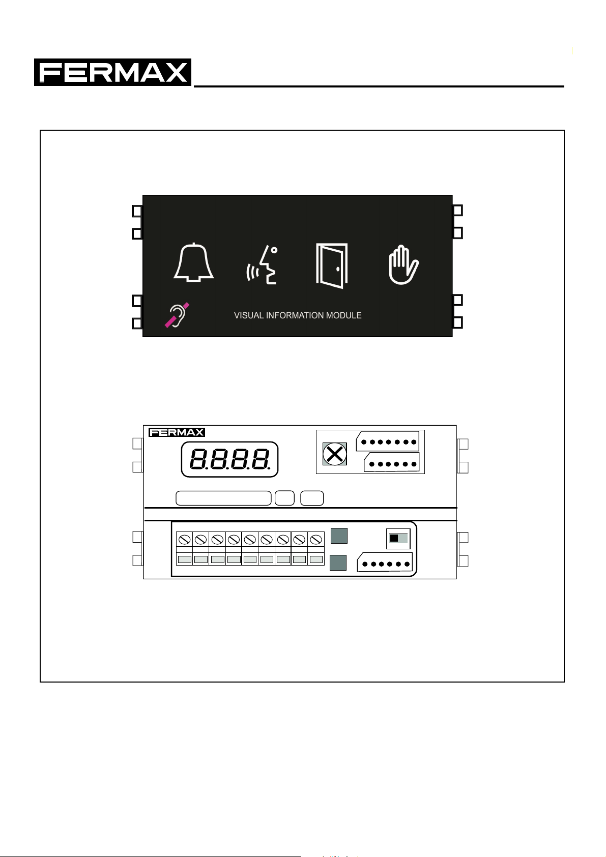
It implements a OneToOne front panel, that provides visual information to each of the operating status (calling,
conversation, door open and system busy).
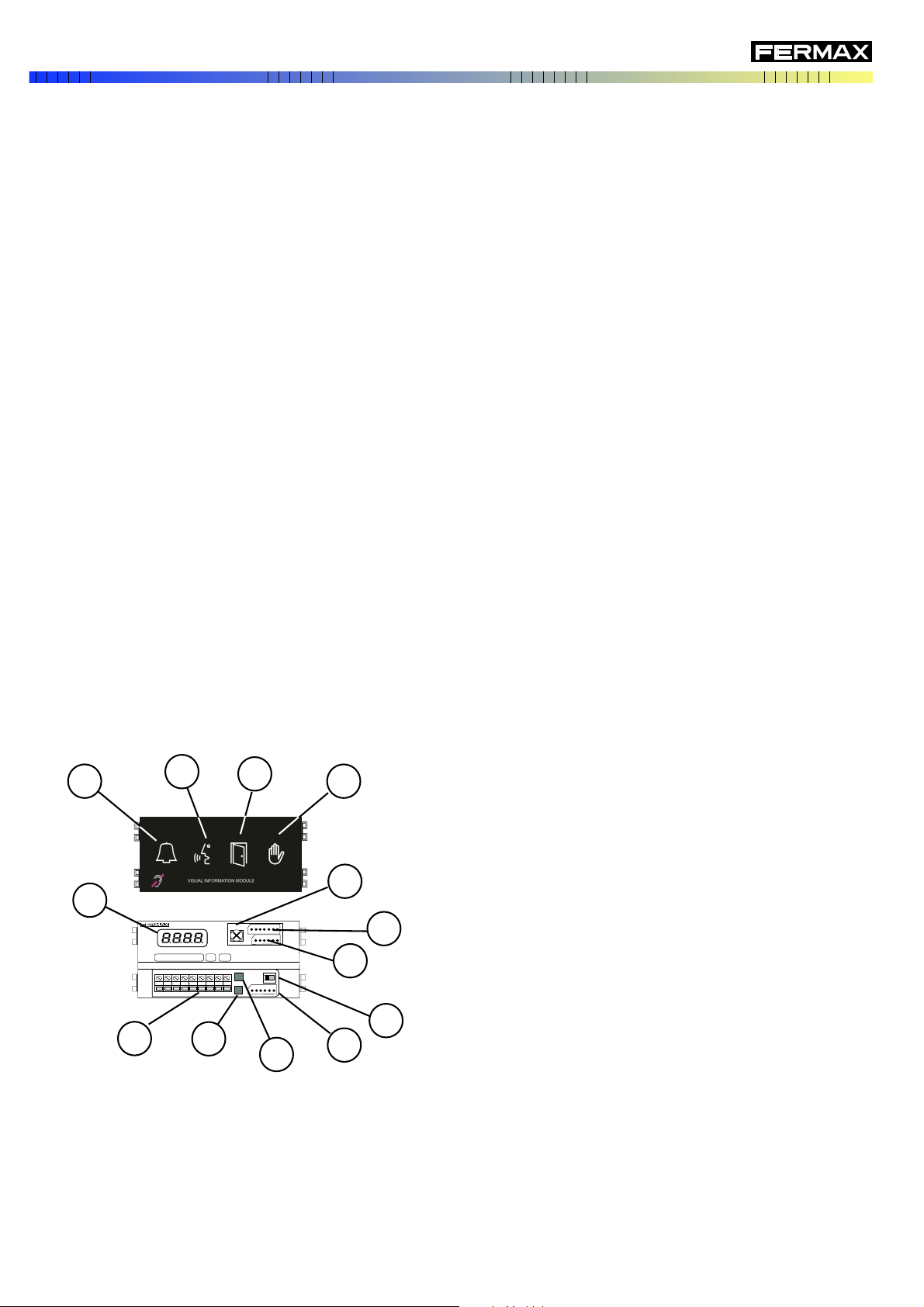
1. Call indicator. Lights up after a call is made.
2. "In conversation" indicator. Lights while a call is in process.
3. "Open door" indicator. Indicates that the door is opening.
4. "System busy" indicator. Indicates that another panel is in
use.
5. Programming display. To help programming.
6. Acoustic volume indicators regulator
7. CN1 Connector. Amplifier connections (*)
8. CN2 Connector. Button and/or Keyboard Module Connections
(*).
9. Installation connections block. MDS output
10. S Button (black). For programming
11. P Button (red). For programming
12. MDS input on the panels back. If available (*).
13. Audio switch. In order to manually enable the audio with
decoders.
DESCRIPTION OF THE SKYLINE MODULE REF. 7460
INTRODUCTION
(*) Module Ref. 7460 comes with the required cables for pre-assembly on the panel.
DESCRIPTION OF THE MDS DIGITISER REF. 7460
MDS DIGITIZER REF. 7460
S
+ - D1 D2 2 6
B -
12
13
8
7
6
11
10
9
5
1
2
3
4
PAG. 4
ASSEMBLY OPTIONS
* Calls to residences are made by pressing the corresponding call button.
* You can program the phones both sequentially and individually (or
MDS/VDS decoders) for the MDS installations with the VDS).
* You can inversely program the buttons,that is, assign a button to an
already programmed telephone.
* The general parameters may not be configured, even though you can
check the status of said configuration.
* The maximum number of modules to insert depends on the systems
limitation (9999 terminals for MDS installations).
* You can "reset buttons," that is, put all buttons to a default configuration
(with the code "0000"). This is useful if you do not know the current
programming status, and want to start from a known configuration.
* Calls to residences are made by pressing the corresponding telephone
number on the keypad.
* You can program all of the system's configuration parameters.
* You program the telephones and decoders and change the number of a
specific telephone individually.
* You can also open the door by entering a 4 digit code. Even though to
activate this code for the first time you need to access the back of the
panel. You can change it from the keypad itself (without dismounting the
wall panel). This function can be deactivated from the keypad itself. This
way to activate it again, you must access the back of the panel.
* You can restore the system to night mode, in which case you need to put
it in this mode and then it isn't available or accessible at the Central Guard
Unit.
* You can reset the system's configuration parameters to default. This is
useful if want to start from a known status.
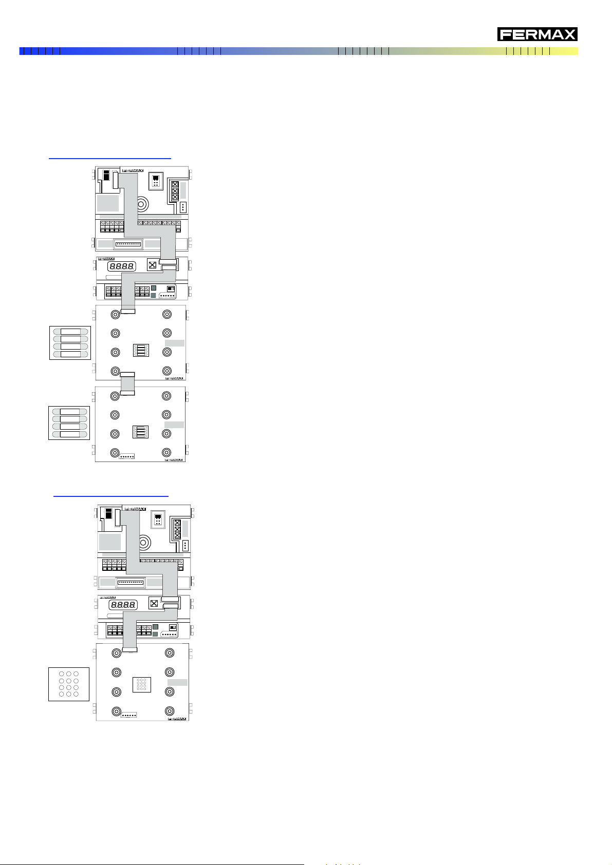
Depending on the modules it is combined with (keypad, buttons or both), the Digitiser offers different features.
BUTTON ONLY PANELS
KEYPAD ONLY PANEL
DESCRIPTION OF THE MDS DIGITISER REF. 7460
MDS DIGITIZER REF. 7460
S
+ - D1 D2 2 6
B -
AMPLIFICADOR 4 + N
4+N AMPLIFIER
AMPLIFICATERU 4+N
4 + N VERSTARKER
VDS/BUS2
CN1
INPUT
OUTPUT
CN2
MDS DIGITIZER REF. 7460
S
+ - D1 D2 2 6
B -
AMPLIFICADOR 4 + N
4+N AMPLIFIER
AMPLIFICATERU 4+N
4 + N VERSTARKER
VDS/BUS2
CN1
INPUT
OUTPUT
CN2
VDS/BUS2
CN1
INPUT
OUTPUT
CN2
PAG. 5
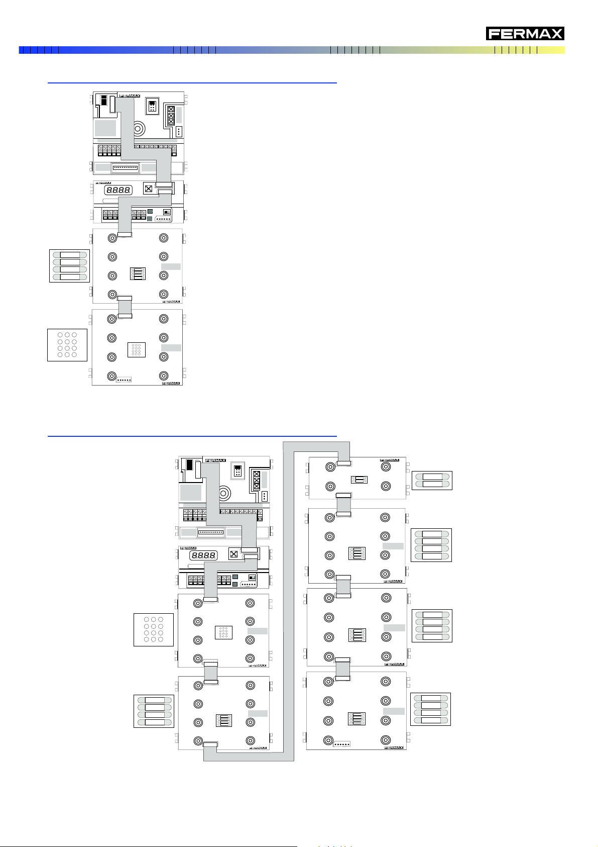
* Calls to residences are made by pressing the corresponding telephone
number on the keypad.
You can also make a call to one or more of the homes via the corresponding
button, if assigned to a residence, since you can also assign telephone
numbers to buttons.
This is useful, for example, if you want certain homes, offices or shops
to be able to receive calls directly (via the button), instead of dialling a
numeric code.
* Assigning a telephone number to a button is done on the keypad itself,
not needing to access the residence.
* Just like on the keypad only panels, you can program all of the system's
configuration parameters and you can also reset the parameters and
buttons.
This configuration is basically the same as the previous one (button module/modules "before" the keypad). The only
difference is aesthetic.
KEYPAD + BUTTONS PANEL (keypad "before" the buttons)
DESCRIPTION OF THE MDS DIGITISER REF. 7460
BUTTONS + KEYPAD PANEL (buttons "before" the keypad)
VDS/BUS2
CN1
INPUT
OUTPUT
CN2
MDS DIGITIZER REF. 7460
S
+ - D1 D2 2 6
B -
AMPLIFICADOR 4 + N
4+N AMPLIFIER
AMPLIFICATERU 4+N
4 + N VERSTARKER
VDS/BUS2
CN1
INPUT
OUTPUT
CN2
OUTPUT
AMPLIFICADOR 4 + N
4+N AMPLIFIER
AMPLIFICATERU 4+N
4 + N VERSTARKER
MDS DIGITIZER REF. 7460
S
+ - D1 D2 2 6
B -
VDS/BUS2
CN1
INPUT
OUTPUT
CN2
VDS/BUS2
CN1
INPUT
OUTPUT
CN2
VDS/BUS2
CN1
INPUT
CN2
VDS/BUS2
CN1
INPUT
OUTPUT
CN2
VDS/BUS2
CN1
INPUT
OUTPUT
CN2
VDS/BUS2
CN1
INPUT
OUTPUT
CN2
PAG. 6
TECHNICAL FEATURES
The MDS Digitiser is an auxiliary device that allows you to configure a SKYLINE panel to be integrated in the MDS
DIGITAL installations or combinations of MDS DIRECT with MDS CITY or VDS.
The configuration of the mode in which it should function (GENERAL ENTRANCE or INTERIOR BLOCK), is done
via a simple programming after the system installation, keeping in mind the installation's characteristics, and in
which no tool or special equipment is required.
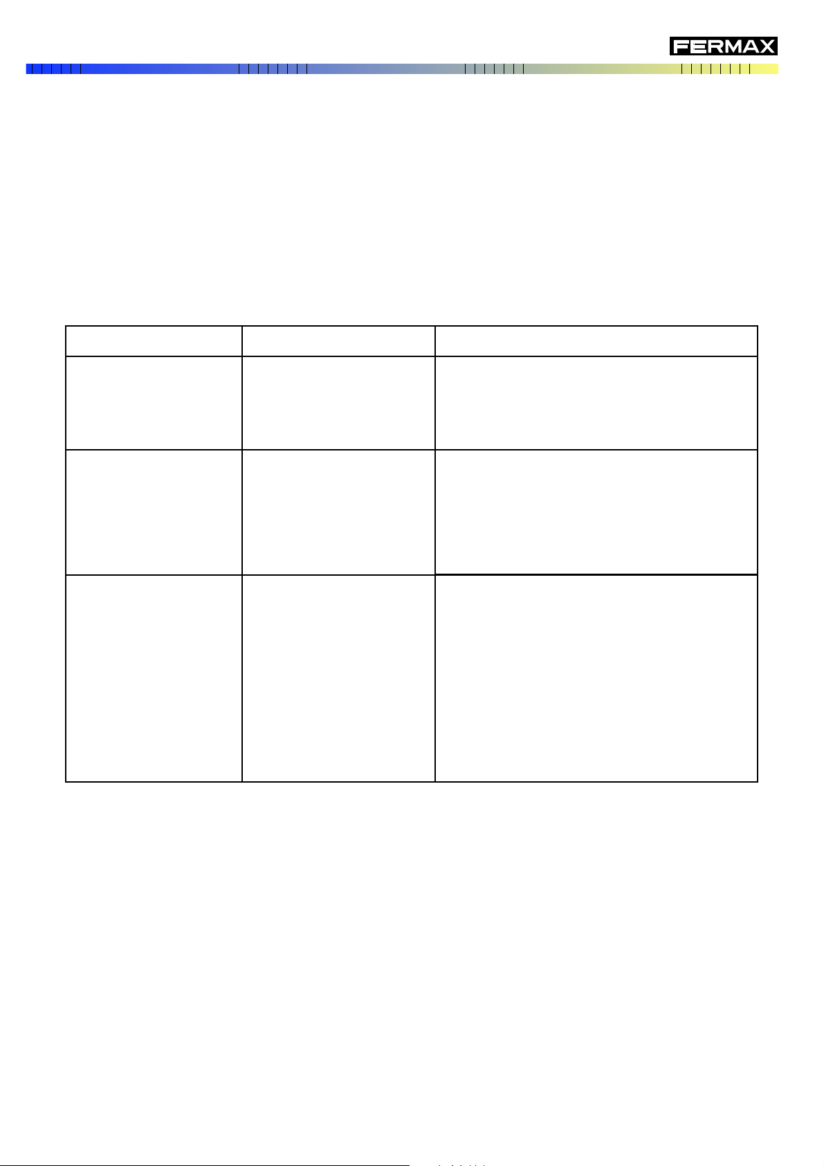
The following table specifies the limitations of each of the possible combinations:
The main technical characteristics of the MDS Digitiser are as follows:
* Programming via 2 buttons. With a digital display of 4 digits that help programming. This allows for the
programming of MDS DECODERS, MDS/VDS DECODERS when programming and changing already programmed
telephone numbers.
* Activation time of the lock release is programmable between 1 and 99 seconds, and indistinctly for the opening
from homes or from the button inside the entrance hall.
GENERAL ENTRANCES
INTERIOR BLOCKS
LIMITS
Observations:
* You can not configure the MDS DIGITAL combined with the Digitiser configured as GENERAL ENTRANCE,
since the management of the general entrances is done via the MDS Central Unit via the panel bus.
* "If the installations with MDS Digitiser that are not developments (only one block), the limit is 5 accesses and
9999 homes.
DESCRIPTION OF THE MDS DIGITISER REF. 7460
MDS DIGITAL
- 32 accesses to the General Entrance and/or DIGITAL
Guard Units.
- 99 interior blocks
- 99 telephones per block
Panel with Digitiser, configured
as an INTERIOR BLOCK.
Panel with Digitiser,
configured as GENERAL
ENTRANCE
- 5 accesses of MDS DIRECT General Entrance.
- 1 MDS DIRECT Guard unit
- 99 interior blocks. 9 accesses per block.
- 99 telephones per block
Digitiser panel, configured as
INTERIOR BLOCK
Digitiser panel, configured
as a GENERAL
ENTRANCE
VDS Panel
- 5 accesses of MDS DIRECT General Entrance.
- 1 MDS DIRECT Guard unit (general)
- 1 VDS guard unit per each block (local)
- 99 interior blocks. 2 accesses per block
- 199 telephones per block (installations up to 9
blocks).
- 99 telephones per block (installations from 10 to
99 blocks)
- installations up to 9999 individual homes
PAG. 7
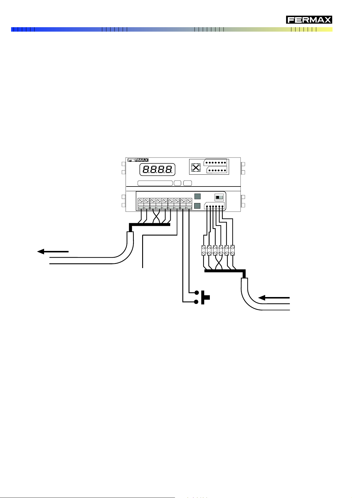
Digitiser general connections:
BUS OUTPUT
(to next panel or decoders)
+, - : Power supply 12 Vdc.
D1, D2: MDS BUS
2, 6: Audio
S: Video exchange control
B, - : Door Open Button
to the switcher's "S"
(if the panel is video)
Inside door open button
(optional)
For more details, see corresponding installation diagram.
BUS ENTRY from the
previous panel (if available).
* Maximum and minimum programmable conversation time according to the following sections:
SECTION 1: Maximum time = 60 seconds. Minimum time = 16 seconds
SECTION 2: Maximum time = 120 seconds. Minimum time = 32 seconds
SECTION 3: Maximum time = 180 seconds. Minimum time = 48 seconds
* Dynamic start-up routine: this automatically detects the type of modules (keypad and/or buttons) connected,
and adjusts the menu accordingly, since they are different depending on whether it is a button, keypad or mixed
panel.
TECHNICAL SPECIFICATIONS
- Power supply: 12 Vdc/ 150 mA (max)
- BUS: MDS FERMAX protocol on RS-485
- Operating temperature: -10º C, +40º C
- IP=43; IK=05
DESCRIPTION OF THE MDS DIGITISER REF. 7460
+, - , D1, D2, 2, 6
MDS DIGITIZER REF. 7460
S
+ - D1 D2 2 6
B -
+ - D1 D2 2 6
S B -
PAG. 8
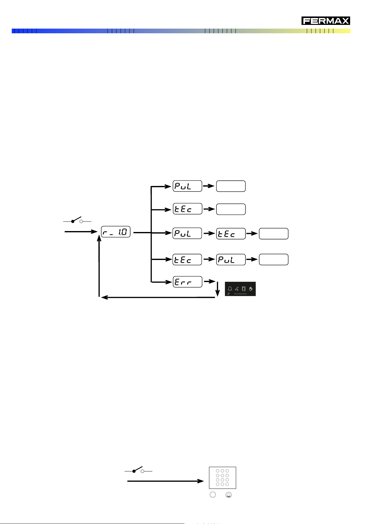
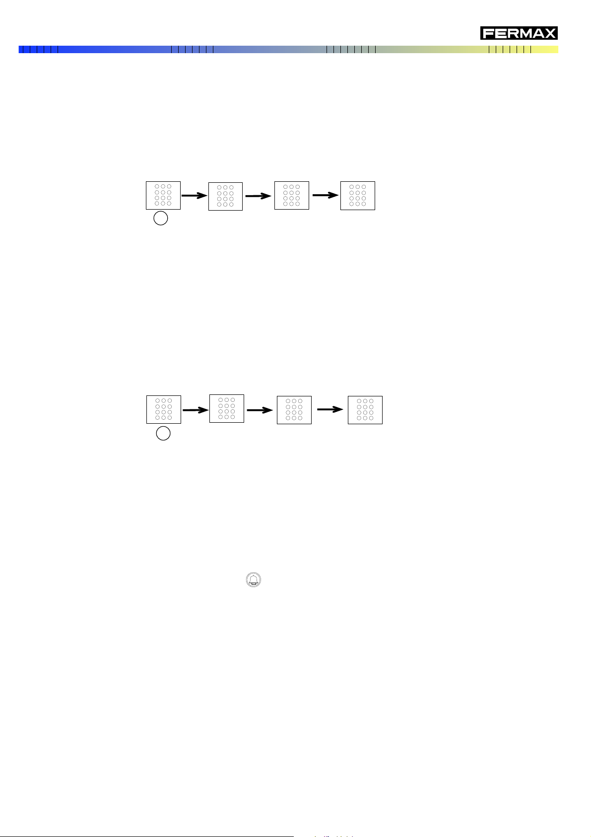
START-UP ROUTINE
The MDS Digitiser has a start-up routine that allows the installer to verify if the modules connection has been
properly made, otherwise, if there is a problem with the connections, and the information on the incorporated
firmware version.
After powering it, the front display shows the firmware version and then indicates the type of modules detected and
their order, that is, the first information indicates what type of module is connected directly to the Digitiser, and the
following information indicates the next one's or module's type.
If no module is detected (due to a failure or if not connected), this routine will continue to repeat, until one is detected.
The digitiser's front indicators blink and the display only indicates the firmware version and the "Err" (error).
The type or types of modules detected will determine the panel's operating mode (MDS DIRECT, MDS CITY or
mixed). The following diagram schematically represents this start-up routine:
RESTORING DEFAULT SETTINGS
You can reset the Digitiser's configuration to its default values. This is useful, for example, if you don't know the
mode it's configured in and want to start from a known value.
The default configuration values are as follows:
- Panel number: 01
- Block number: 00
- Lock-release activation time (when opened from the residence): 3 seconds.
. Lock-release activation time (when opened from the entrance hall's button): 6 seconds
- Conversation time. Max.: 60 seconds. Min: 16 seconds
- NIGHT MODE Panel.
This operation can only be performed on panels with the keypad module, or those provisionally connected to one.
The steps for restoring are to power the system and enter "A-7-0-8-BELL-9" on the keypad in less than 1 minute's
time.
DESCRIPTION OF THE MDS DIGITISER REF. 7460
Before 1 minute
Button module/s detected
This is repeated as long as no module is detected
(keypad and/or buttons) connected to the Digitiser
The indicators blink
Keypad detected
Buttons + keypad module/s detected
No buttons or keypads detected
Version of the
Digititiser (1.0)
Keypad + button module/s detected
ON
708 9
A
OK
OK
OK
OK
ON
PAG. 9
The MDS systems that have some type of Central Guard Unit may function in DAY MODE: The calls from the street
panels to the homes are only received in the Guard unit, or in NIGHT MODE, the calls are received in the homes.
Changing from one mode to another is done from the Central Guard Unit.
A system may be configured in DAY MODE, and not be able to make the change to NIGHT MODE, since the Central
Guard Unit isn't available or accessible. In this situation, the calls are not received in the homes, but are forwarded
to the Central Guard Unit (even if the central is not physically connected).
From the panel with Digitiser you can restore the NIGHT MODE panel and then allow for calls to homes.
This operation is only done via the panels with keypad module, or provisionally connected to a module.
The procedure is the following:
- Press the "A" key
- Mark the sequence "3 - 1 - 4 - 1"
- Mark the sequence "0 -0 -0 -0" (twice).
This resetting can also be done via the programming. See the SYSTEM PROGRAMMING section.
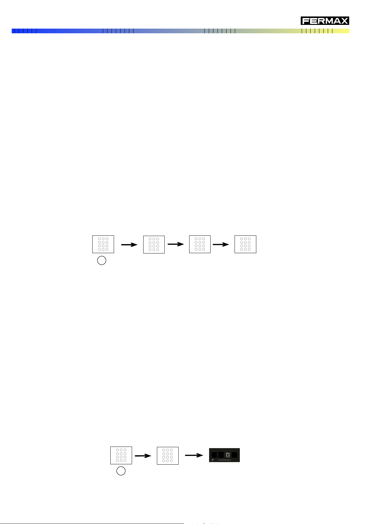
RESTORING NIGHT MODE
OPENING THE DOOR WITH THE PIN
The panels with keypad module have the front entrance door open function via a general 4-digit PIN. Upon entering
this code via the keypad, you can open the door.
This code is programmed and active via the SYSTEM PROGRAMMING (see the corresponding section), even
though it can be changed later from the keypad itself. It can be deactivated as well. To activate and program again,
you need to do so via the SYSTEM PROGRAMMING, that is, accessing the front part of the panel.
The way to open the door via the PIN is as follows:
- Press the A key
- Mark the PIN code. The "door" icon on the digitiser's front OneToOne is lit.
The procedure for changing the code via the keypad is as follows:
XXXX: Current code
DESCRIPTION OF THE MDS DIGITISER REF. 7460
3141
0000 0000
A
XXXX
A
PAG. 10
XXXX: Current conde
YYYY: New code (do not use 3141)
XXXX: Current code
The deactivation procedure (disable) for the PIN opening is as follows:
- Press A key
- Mark the sequence "3 - 1 - 4 - 1"
- Mark the 4 digits of the current code
- Re-enter "3 - 1 - 4 -1"
- Press the A key
- Mark the 4 digits of the current code
- Mark the 4 digits of the new code (do not use 3-1-4-1, since that's the system's internal code).
DESCRIPTION OF THE MDS DIGITISER REF. 7460
CALLING THE GUARD UNIT
If an installation includes an MDS CITY/DIRECT Central Guard Unit ref. 2532, and if in DAY MODE, calls from the
General Entrance street panels are received in the guard unit, instead of the homes.
The panel also generates calls to the guard unit in the following cases:
- Panels with keypad: pressing "0" +
- In panels with buttons: from any button that has not been programmed (or if programmed as "0000").
XXXX
YYYY
A
3141
A
3141
3141
XXXX
PAG. 11

Once installed, programming the Digitiser is done via the P and S buttons on its backside.
Via this programming you define the parameters of the panel in which they are mounted, along with other operating
parameters.
It has a DISPLAY with 7 segments that offer visual information to help programming.
This manual indicates which screens are shown on this display in each programming step.
Besides the light indicators, the Digitiser can emit a deep (mook) acoustic tone during programming to indicate an
error in the data-entry, or a high acoustic tone (beep) to indicate that the operation is performed correctly.
Before programming, we have to clearly understand the configuration parameters in order to avoid a malfunction in
the operating system.
These parameters are as follows:
GENERAL ENTRANCE/INTERIOR BLOCK: Within a development we must indicate if the panel is installed as its
GENERAL ENTRANCE, otherwise as a panel installed as a BLOCK entrance INTERIOR.
If installed in an individual building (not a development) it must be considered as an INTERIOR BLOCK.
* The default configuration is INTERIOR BLOCK
* Upon programming a telephone from a panel configured as INTERIOR BLOCK, the number entered is
automatically added to the block number.
For example, if the INTERIOR BLOCK is number 07 and we program a telephone as 23, the number really
programmed is 723.
Likewise, upon making a call from the INTERIOR BLOCK, we mark 23, but the call code is really 723.
From the GENERAL ENTRANCE (which does not add anything), to call this number we have to mark 723.
BLOCK NUMBER: In the case of an INTERIOR BLOCK panel, you must identify in which block it is installed. For this,
each of the panels must be configured with the corresponding BLOCK NUMBER.
* The possible values to assign are 00 to 99. Use sequential numbers starting with 00.
* Default value is 00.
* In the case of panels configured as a GENERAL ENTRANCE, this parameter is not configured.
PROGRAMMING
Antes de proceder a la programación, tendremos que tener claro los parámetros de configuración, con el fin de
evitar malfuncionamientos en la operativa del sistema.
Estos parámetros son los siguientes:
ENTRADA GENERAL/BLOQUE INTERIOR: Dentro de una urbanización, debemos indicar si la placa está instalada
como una ENTRADA GENERAL a la misma, o por el contrario es una placa instalada como entrada a un BLOQUE
INTERIOR.
En el caso en que se instale en un edificio individual (que no sea una urbanización), se debe considerar como
BLOQUE INTERIOR.
* La configuración de fábrica es BLOQUE INTERIOR
* Al programar un teléfono desde una placa configurada como BLOQUE INTERIOR, al número
introducido se le añade automáticamente el numero del bloque.
Por ejemplo, si el BLOQUE INTERIOR es el número 07 y programamos un teléfono como 23, el número
con el que realmente es programado el teléfono es el 723.
Del mismo modo, al realizar la llamada desde el BLOQUE INTERIOR, marcaremos 23, pero el código
de llamada enviado realmente será 723.
Desde la ENTRADA GENERAL (que no añade nada), para llamar a este número de teléfono, tendremos
que marcar 723.
NUMERO DE BLOQUE: En el caso de placas de BLOQUE INTERIOR, es necesario identificar en qué bloque está
instalada. Para ello, cada una de estas placa se ha de configurar con el NUMERO DE BLOQUE correspondiente.
* Los posibles valores a asignar son del 00 al 99. Utilizar número correlativos, empezando por el 00.
* El valor de fábrica es 00.
* En el caso de placas configuradas como ENTRADA GENERAL, este parámetro no se configura.
MDS DIGITIZER REF. 7460
S
+ - D1 D2 2 6
B -
P
S
DISPLAY
PAG. 12

PROGRAMMING
PANEL NUMBER: Each panel in the development must be identified. For this you must assign
THE PANEL NUMBER There must not be a repeated panel number amongst the GENERAL ENTRANCES and
no repeated panel number amongst the INTERIOR BLOCK.
* The possible values to assign are 01 to 05 (if the panel is configured as a GENERAL ENTRANCE,
or from 01 to 09 if the panel is assigned as an INTERIOR BLOCK. Use correlative numbers starting
with 01.
* Default value is 01.
* Do not use value 00 for PANEL NUMBER
PAG. 13
Depending on the type of module/s detected during start-up, the Digitiser will only present the options relative to
the type of panel, according to the following table:
To exit the programming, repeatedly press the P button, from the GENERAL OPTIONS MENU until the display
turns off.
The reader will automatically exit programming mode after 120 seconds of inactivity.
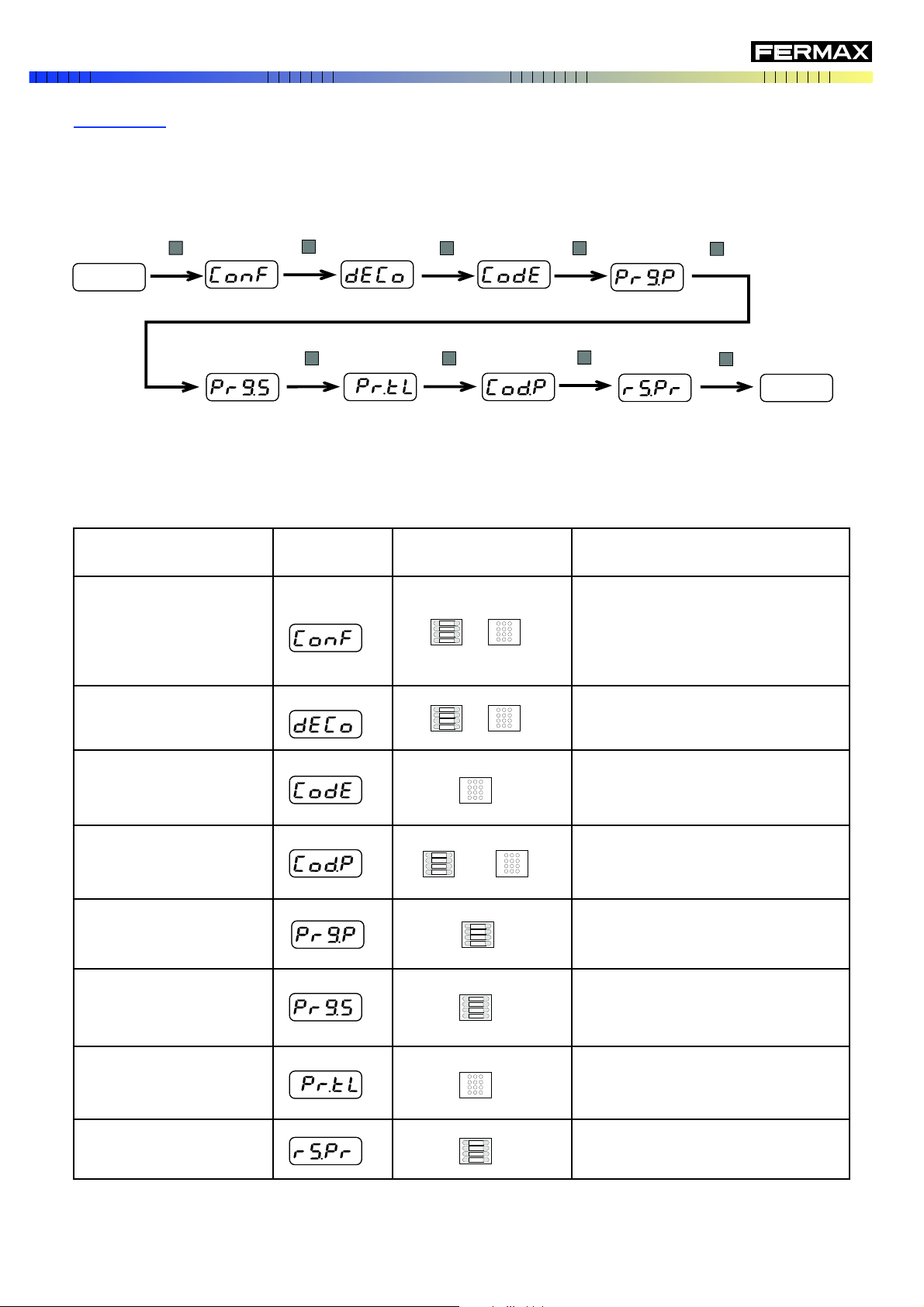
PROGRAMMING
PARAMETER
CONFIGURATION
GENERAL
OPTION
DISPLAY
PROGRAMMING
DECODERS
ENABLE AND ASSIGN PIN
TO OPEN THE DOOR
ASSIGN A TELEPHONE
NUMBER TO A BUTTON
INVERSE
PROGRAMMING OF
BUTTONS
SEQUENTIAL
PROGRAMMING OF
BUTTONS
SEQUENTIAL
PROGRAMMING OF
TELEPHONES
RESET BUTTONS
NECESSARY
MODULES
OBSERVATIONS
Programming the panel's general parameters.
On panels with only buttons, you can not
program these parameters, but you can verify
the programming status.
Programming decoders (both for MDS and
VDS)
Assign a telephone number to a button for
direct calling
Assign a button to a specific telephone
(previously programmed).
Assign the buttons to telephones sequentially.
Assign/change the number of a specific
phone.
Set all panel buttons to the default settings
(with the number "0000").
Programming and activation of the PIN to
open the front entrance door.
In order to enter in the Digitiser's programming mode, press the P button until the first option on the GENERAL
OPTION'S MENU appears (Parameter Configuration).
Repeatedly press until reaching the desired option, according to the following diagram.
MAIN MENU
/
+
/
P
P
P P
P
P
P
P
P
PAG. 14
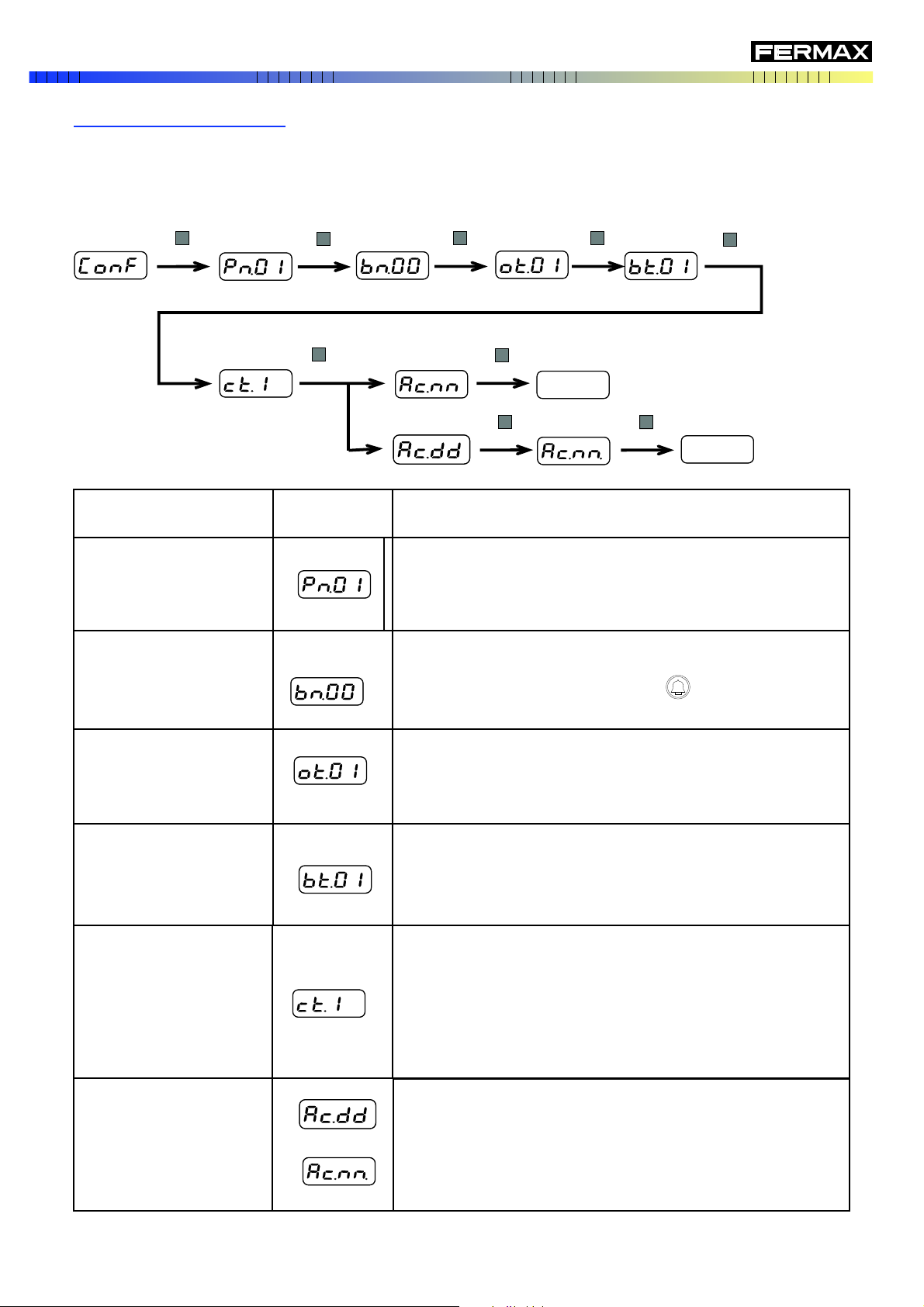
With this we option we program the panel's general parameters.
Starting from the general option CONFIGURING PARAMETERS, press the S or P button, following the attached
diagram, to access the desired parameter.
PROGRAMMING
PANEL NUMBER
Pn.xx
INDICATIONS
DISPLAY
OPEN DOOR TIME
(from the homes)
ot.xx
OBSERVATIONS
Identification of the panel number of a development or block with
various accesses.
Possible values: 01-05 (if a General Entrance)
01-09 (if an Interior Block).
BLOCK NUMBER
bn.xx
Identification of the block number where the panel is installed.
Possible values: 00-99
If a General Entrance, press the key :
(The display will indicate Egrl)
This is the door lock-release activation time in seconds when the
door opening command is activated from the home's telephone.
Possible values: 00-99
OPEN DOOR TIME
(from the entrance)
bt.xx
Determines the minimum time guaranteed and the maximum time
allowed for conversations maintained between this panel and a
house .
Possible values: 01 = T.max: 60 sec. and T.min.: 16 sec.
02 = T.max: 120 sec. and T.min.: 32 sec.
03 = T.max: 180 sec. and T.min.: 48 sec.
CONVERSATION TIME
(maximum and minimum)
ct.xx
This is the door lock-release activation time in seconds when the
door opening command is activated from the front entrance's
telephone.
Possible values: 00-99
RESETTING NIGHT MODE
PANEL
Ac.dd (day mode)
Ac.nn (night mode)
This allows you to change the operating mode from Day mode
to Night Mode in cases where it is not possible to do so from the
Central Guard Unit.
Configuration of Parameters
S
P
P P
P
P
P
P
P
PAG. 15
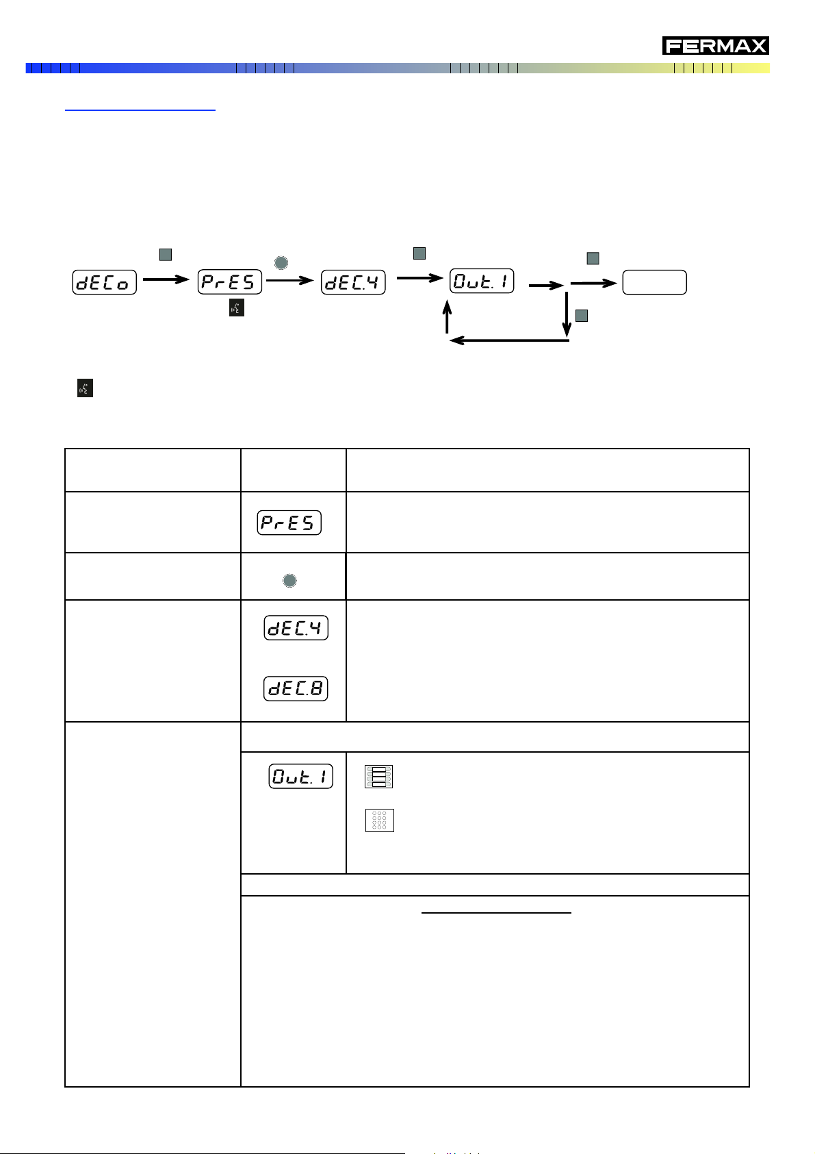
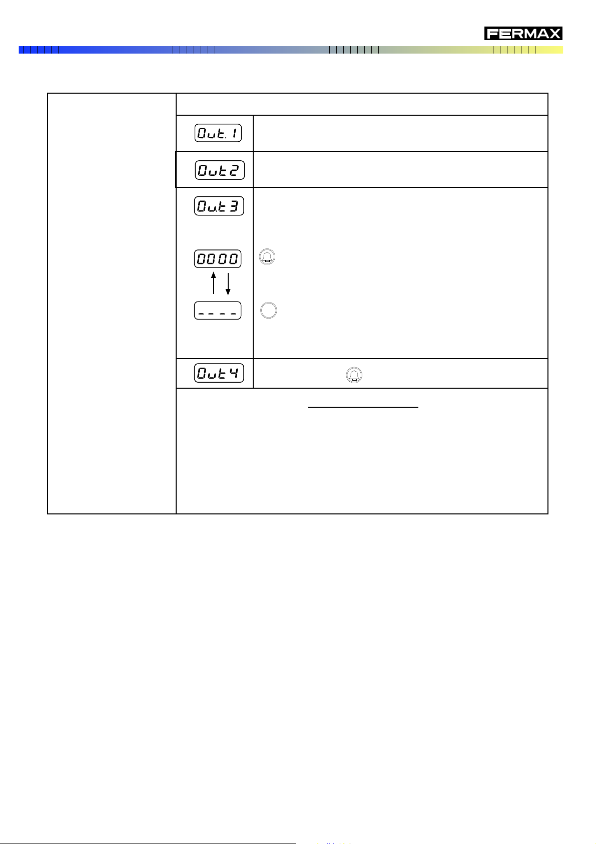
Repeat with all Decoder outputs
This option allows you to program the MDS or VDS decoders configuring the different panel general parameters.
Starting from the general DECODER PROGRAMMING option, follow the indications on the following diagram and
table:
Repeat these steps for all
Decoders to be programmed
PROGRAMMING
PRG
PANEL PREPARED
INDICATIONS
DISPLAY
OBSERVATIONS
The panel is already prepared for programming the Decoder. You
have 120 seconds to put the decoder in programming mode.
Press the programming button of the decoder to be programmed.
The Display will indicate the type of Decoder to be programmed
Possible values:
dEc.4: Decoder MDS de 4 outputs (or Decoder VDS configured
as range)
dEc.8: Decoder MDS de 8 outputs (or Decoder VDS configured
as DECODER 8)
DECODER PREPARED
PREPARAR DECODER
PROGRAM DECODER
If a MDS DECODER or VDS DECODER VDS configured as a DECODER 8
Press the button to assign a telephone connected to the
first decoder output, or
Dial the number of the home to assign (two digits), or dial
A if you want to exit without programming. (It is really
programmed with the code "0 0 0 0".
Repeat these steps with the remaining decoder outputs
DISPLAY INDICATIONS
" - - - -" : the decoder output has not been programmed yet.
" x x x x" : telephone number to be programmed.
If an Interior Block panel, the assigned number is automatically that of the
Interior Block Number.
After confirming with "S":
"E r r " : the number being programmed is already assigned.
"Good" : the number has been programmed correctly.
Audio is established between the panel and the decoder, so you can communicate via the
panel and decoder by connecting a telephone jack to this..
Decoder Programming
PRG
Audio ON
S
S
S
S
Audio ON
PAG. 16
See the VDS Decoder's Technical information for more details.
PROGRAMMING
A
PROGRAM DECODER
If a VDS DECODER configured as a range
Indicate the first address in the range and confirm with "S".
Indicate the last address in the range and confirm with "S".
Allow VDS telephones from the interior block to be
programmed from the General Entrance.
Useful for cases in which there is no interior panel.
VDS telephones may only be programmed from the VDS
panel of the same block.
No function. Press and confirm with"S"·
After selecting the option confirm with "S".
DISPLAY INDICATIONS
" - - - -" : the decoder output has not been programmed.
" x x x x" : number to be entered. .
After confirming with "S":
"E r r " : the number being programmed is not possible.
"Good" : the number has been properly entered.
Indicate if you want to be able to program the telephones
from the General Entrance panel or from the block's VDS
Panel.
PAG. 17
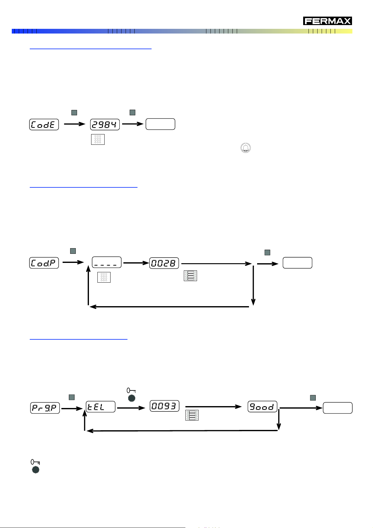
Telephone number to
assign to a button
(Example, 28).
press the button
to assign
Repeat if you want to assign more buttons
This option allows you to activate and program a PIN, via which the user can open the front entrance door.
Once the ENABLE AND ASSIGN PIN option has been selected from the main menu, follow the steps on the following
diagram:
Enter PIN number (4 digits). EX. "2 9 8 4".
Do not use 3 1 4 1.
If you wish to delete or disable this function, press the key:
This option allows you to, on mixed panels (keypad + buttons), assign a button to facilitate the call to a specific
telephone.
Once the ASSIGN A TELEPHONE NUMBER TO A BUTTON option has been selected from the main menu, follow
the steps on the following diagram:
This option is only available on panels with only buttons, and allows you to assign a button an already programmed
telephone.
Once the INVERSE PROGRAMMING OF BUTTONS option has been selected from the main menu, follow the
steps on the following diagram:
Press button
to assign
Err: Telephone not programmed
Good: Properly Assigned
XXXX: Telephone number to assign.
(Example: 93)
Panel prepared
Repeat if you want to program more buttons
Press the door-opening button on the telephone to assign
PROGRAMMING
Assign a telephone number to a button
Inverse programming of buttons
Enable and assign the PIN to open the door
S
S
S
S
S
S
PAG. 18
 Loading...