

Page 1
REF. 2430
É
S
Cod.: 94076 V09/11
8
BUS
37
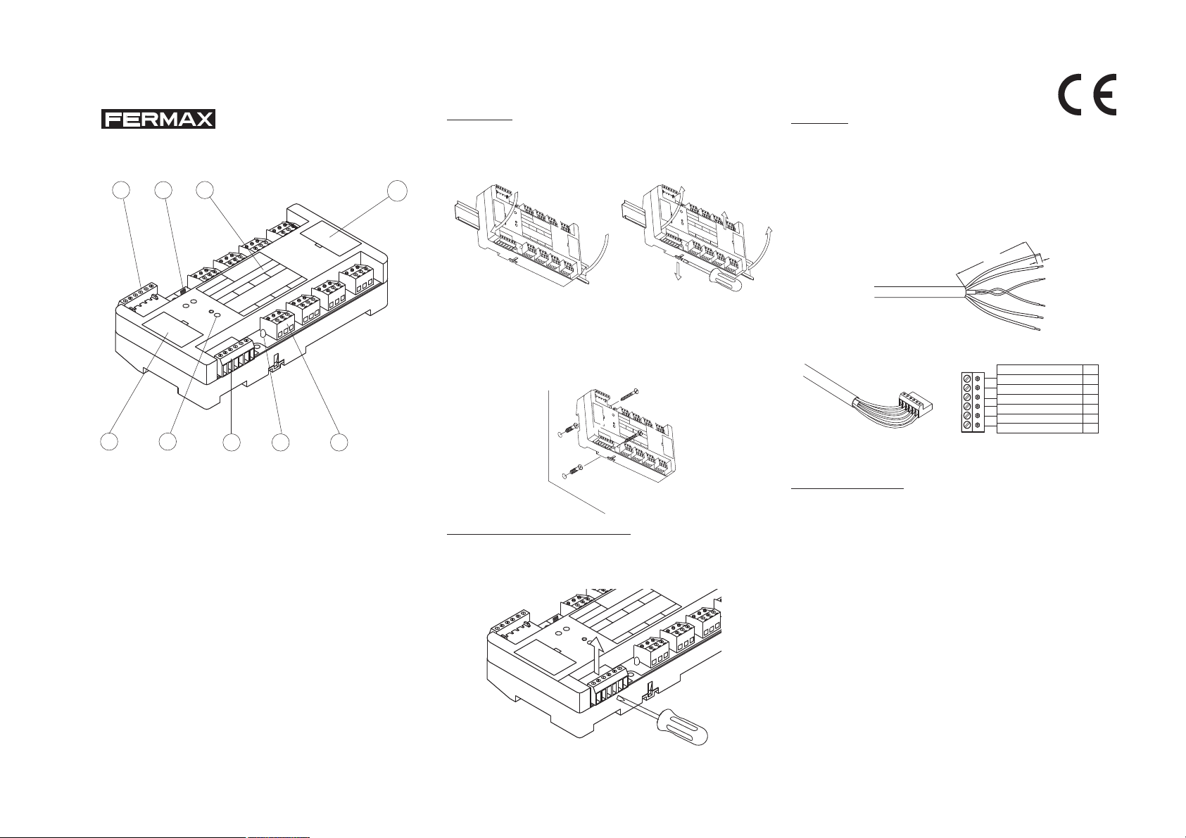
1. Conector del cable BUS
para conectar los siguientes decoders,
según el correspondiente
esquema de cableado.
2. Conector del cable BUS
de los anteriores decoders o de la Unidad
Central, según esquema
de cableado.
3. Botón PGM (seguir
instrucciones del Manual
de Programación del
Decoder).
4. Conector del relé.
Abrocharlos según esquema de cableado.
DECODER DE 8 RELES
61
E R
R D
E
D
O
D
C
S
E
Y
D
LA
E
X
R
A
M
N
I
º:
A
P
S
R
N
I
N
E
D
E
A
M
R
F
E
D
O
REF. 2430
C
E
D
5
1
M
PG
BUS
26
D2
D1-
+
2 5 4
SISTEMA MDS
Guia de Instalación del
S
LÉ
E
R
E
D
O
C
E
8
4
S
7
Y
A
L
E
3
/ R
6
S
E
L
E
2
R
nc
c
no
nc
c
no
5. Led indicador. Una vez el
sistema esté en marcha se
encenderá cuando se
active el correspondiente
relé.
6. Etiqueta de identificación
del Decoder.
7. Conector de programación/test por PC (debajo
de la tapa).
8. Desconexión de emergencia. Permite liberar todos
los relés en situaciones
especiales.
9. Puentes de test (debajo
de la tapa).
nc
c
no
nc
c
no
Instalación
El Decoder de 8 relés puede instalarse tanto sobre
carril DIN como atornillado sobre la pared:
Cableado
Realice el cableado del decoder siguiendo las
instrucciones del correspondiente esquema de cableado.
* Instalación sobre carril DIN
9
B
U
S
F
E
R
M
M
A
D
E
I
N
A
S
P
A
X
I
N
R
E
F
.
2
D
4
ECOD
3
0
D
E
ER DE RELÉS
C
RELAYS D
O
P
D
G
E
R
M
ECO
N
º
DER
:
B
U
5
S
6
R
1
E
L
E
7
S
/
R
2
E
L
A
8
Y
+
S
3
D
1
D
2
4
2
6
n
o
c
n
c
n
o
c
n
c
n
o
c
n
c
n
o
c
n
c
Montaje
B
U
S
F
E
R
M
M
A
D
E
I
N
A
S
P
A
X
I
N
R
E
F
.
2
D
4
E
3
C
0
O
D
D
E
E
R
C
D
R
O
E
E
L
R
A
P
D
E
Y
L
S
G
E
É
D
S
R
M
E
N
C
O
º:
D
E
R
B
U
5
S
6
RELES / RELAYS
1
7
2
+
D
8
3
1
D
2
4
2
6
n
o
c
n
c
n
o
c
n
c
n
o
c
n
Desmontaje
c
n
o
c
n
c
* Pelado de los cables
Pele unos 10 cm de la cubierta de la manguera y 0,5 cm
aproximadamente cada uno de los cables. Tenga cuidado
de no dañar la cubierta de los cables.
10 cm
REF. 5918
0,5 cm
* Instalación directamente sobre pared
Utilice los tacos y tornillos que se acompañan, para la
colocación del decoder en la pared. Utilice una broca del
nº 6 para hacer los agujeros de la pared.
B
U
S
F
E
R
M
M
A
D
E
I
N
A
S
P
A
X
I
N
R
E
F
.
2
D
4
E
3
C
0
O
D
D
E
E
R
C
R
D
O
E
E
L
R
A
P
D
E
Y
L
S
G
E
É
S
R
D
M
E
N
C
O
º:
D
E
R
B
U
5
S
6
R
1
E
L
E
7
S
/ R
2
E
L
A
8
Y
S
+
3
D
1
D
2
4
2
6
n
o
c
n
c
n
o
c
n
c
n
o
c
n
c
n
o
c
n
c
* Abroche de los conectores
Cableado del BUS de DECODERS
COLOR CABLES REF. 5918
R
E
F
. 5
9
1
8
+
D1
D2
2
6
MARRON
NARANJA
NEGRO (PAR TRENZADO)
BLANCO (PAR TRENZADO)
ROJO
AZUL
+
-
D1
D2
2
6
Una vez cableados, según el esquema de instalación,
vuelva a montar los conectores en su sitio correspondiente.
Recomendaciones
* Tenga especial cuidado en respetar la polaridad de
Desmontaje de los conectores
Utilize un destornillador para sacar los conectores y poder
abrochar los cables de forma sencilla.
L
E
R
R
E
E
D
D
O
R
C
E
E
D
O
D
8
S
6
E
R
1
4
S
7
Y
A
L
E
3
/ R
S
LE
2
c
n
c
o
n
c
n
c
o
n
c
n
c
o
n
26
BUS
FERM
PGM
AX
N
I
A
P
S
IN
E
D
A
M
REF. 2430
DECO
BUS
+
C
E
D
E
R
DER N
5
D1-
Y
A
L
º:
D2
los cables. La incorrecta colocación de algún cable
provocará el no funcionamiento del decoder, del
sistema completo o incluso serias averías en el mismo.
* El decoder se ha de instalar siempre en interiores,
donde no le pueda incidir lluvia o humedad.
* Rellene la Etiqueta de Identificación del Decoder, con
el número de decoder y los números de sensor
asignados, según el esquema de cableado. Esto le
facilitará la posterior programación, revisiones, etc.
NOT AS sobre el DECODER:
- No dejar sin programar la primera dirección.
- No programar diferentes salidas con la misma dirección.
Page 2
REF. 2430
É
S
Cod.: 94076 V09/11
8
BUS
37
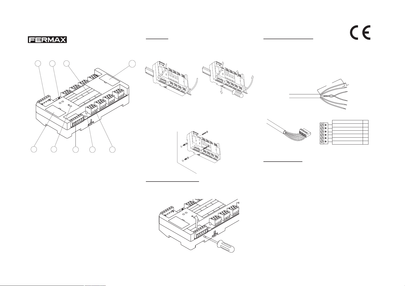
1. BUS cable connector to
the next decoders,
according to the
corresponding wiring
diagram.
2. BUS cable connector
from the previous
decoders or from the
Central Unit, according to
the wiring diagram.
3. PGM button (for programming the Decoder
according to the
Programming Manual).
4. Relay connector.
Connect relay according
to wiring diagram.
DECODER 8 RELA YS
61
O
C
E
D
X
R
A
M
N
I
A
P
S
R
N
I
E
D
E
A
M
F
E
D
O
REF. 2430
C
E
D
M
PG
BUS
D1-
+
2 5 4
MDS SYSTEM
Installation guide for
S
LÉ
E
R
R
E
E
D
D
O
R
C
E
E
D
AY
EL
N
R
5
D2
8
S D
º:
6
R
1
4
S
7
Y
A
L
E
3
/ R
S
E
L
E
2
nc
c
no
nc
c
no
c
no
nc
c
no
26
5. Led indicator. Once the
system starts up, the led
will be ON when relay is
activated.
6. Decoder Identification
label.
7. PC programming/test
connector (under the
cover).
8. Emergency connector.
Allows to release all
relays in emergency
events.
9. Test jumpers (under the
cover).
Installation
The Decoder 8 Sensors can be installed either on a DIN
rail or directly to the wall.
Connecting the decoder
Connect the decoder according to the corresponding wiring
diagram.
* Installation on DIN rail
9
nc
B
U
S
F
E
R
M
M
A
D
E
I
N
A
S
P
A
X
I
N
R
E
F
. 2
D
4
E
3
C
0
O
D
D
E
E
R
C
D
R
O
E
E
L
R
A
P
D
E
Y
L
S
G
E
É
D
R
S
M
E
C
N
O
º
D
:
E
R
B
U
5
S
6
R
1
E
L
E
7
S
/
R
2
E
L
A
8
Y
+
S
3
D
1
D
2
4
2
6
n
o
c
n
c
n
o
c
n
c
n
o
c
n
c
n
o
c
n
c
Mounting
B
U
S
F
E
R
M
M
A
D
E
I
N
A
S
P
A
X
I
N
R
E
F
.
2
D
4
E
3
C
0
O
D
D
E
E
R
C
D
R
O
E
E
L
R
A
P
D
E
Y
L
S
G
E
É
S
R
D
M
E
N
C
O
º:
D
E
R
B
U
5
S
6
RELES / RELAYS
1
7
2
+
D1
8
3
D
2
4
2
6
n
o
c
n
c
n
o
c
n
c
n
o
c
Demounting
n
c
n
o
c
n
c
* Instalallation wall mounting
Use the 2 screws provided to fix the decoder to the wall.
Use a 6 mm drill to make the holes.
B
U
S
F
E
R
M
M
A
D
E
I
N
A
S
P
A
X
I
N
R
E
F
.
2
D
4
E
3
C
0
O
D
D
E
E
R
C
D
R
O
E
E
L
R
A
P
D
E
Y
L
S
G
E
É
S
R
D
M
E
N
C
O
º:
D
E
R
B
U
5
S
6
R
1
E
L
E
7
S
/ R
2
E
L
A
8
Y
S
+
3
D
1
D
2
4
2
6
n
o
c
n
c
n
o
c
n
c
n
o
c
n
c
n
o
c
n
c
* Stripping cable
Remove 10 cm of the cable cover and 0.5 cm from each
wire. Ensure that cable is stripped correctly so that no shorts
are made.
10 cm
REF. 5918
0,5 cm
* Cabling connectors
DECODERS BUS wiring
R
E
F
. 5
9
1
8
+
D1
D2
2
6
WIRE COLOUR REF. 5918
BROWN
ORANGE
BLACK (TWISTED PAIR)
WHITE (TWISTED PAIR)
RED
BLUE
+
-
D1
D2
2
6
After connections are complete insert the connectors onto
the decoder.
Recommendations
* Ensure the correct polarity of the wiring. Incorrect
installation can cause damage to the decoder or make
Removing the connectors
Use a screwdriver to remove the connectors, for easier
connecting of the cables.
L
E
R
R
E
E
D
D
O
R
C
E
E
D
O
D
8
S
Y
6
R
1
4
S
7
Y
LA
E
3
/ R
S
E
L
E
2
c
n
c
o
n
c
n
c
o
n
c
n
c
o
n
26
BUS
FERM
PGM
AX
N
I
A
P
S
N
I
E
D
A
M
REF. 2430
D
BUS
ECO
+
C
E
D
A
L
E
R
DER Nº:
5
D2
D1-
the system fail.
* The decoder must always be installed inside, where
rain or moisture cannot affect it.
* Alwais mark the Decoder Identification Label with
the decoder number and its assigned sensor
numbers, according to the corresponding wi-ring
diagram. This will ensure base of pro-gramming and
servicing.
NOTES on the DECODER:
- Do not leave the first address without programming.
- Do not program different outputs with the same address.
Page 3
+
-
D1
D2
2
6
FARBE KABEL REF. 5918
BLAU
ORANGE
BRAUN
SCHWARZ (VERDRILLTES PAAR)
ROT
WEIß (VERDRILLTES PAAR)
Cod.: 94076 V09/11
É
S
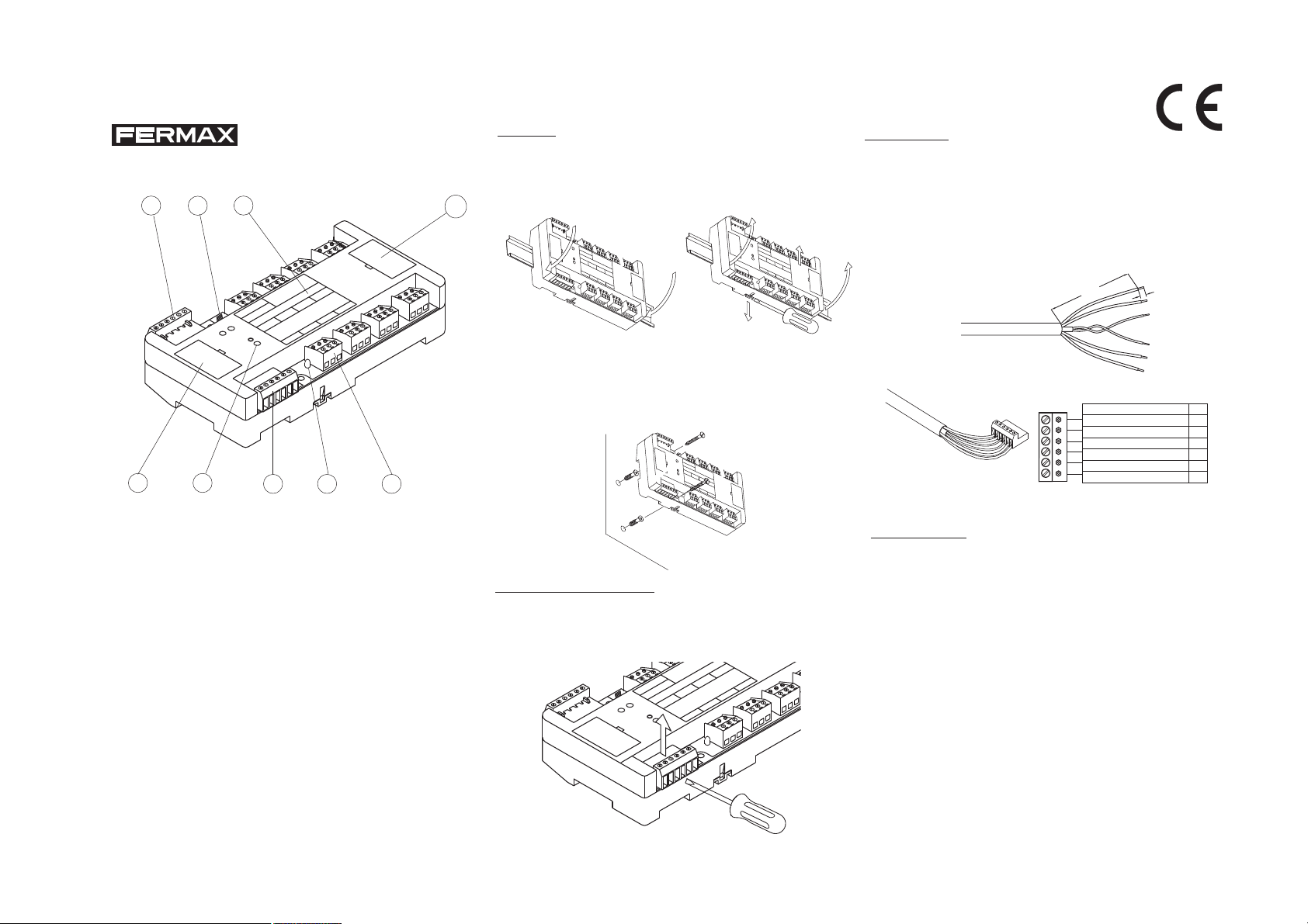
1. Anschluss des BUS-
2. Anschluss des BUS-
3. PGM-Knopf (folgen Sie
4. Relaisanschluss.
REF. 2430
8
BEDIENUNGSANLEITUNGS
DES 8 RELAIS DECODER
61
O
C
E
D
AX
N
I
A
P
S
RM
N
I
E
D
A
M
FE
E
D
O
REF. 2430
C
E
D
BUS
PGM
BUS
D1-
+
37
2 5 4
Kabels zum Anschluss
folgender Decoder,
gemäß des jeweiligen
Verdrahtungsschema.
Kabels der vorherigen
Decoder oder der
Zentraleinheit, gemäß
des
Verdrahtungsschemas.
den Anweisungen des
Programmierhandbuchs
des Decoders).
Abklemmen gemäß
Verdrahtungsschemas.
MDS-SYSTEM
S
É
L
E
R
R
E
E
D
D
O
R
C
E
E
D
D
S
Y
A
L
E
R
º:
N
R
5
D2
8
4
S
7
Y
A
L
E
3
/ R
6
S
E
L
E
2
R
1
nc
c
no
nc
c
no
nc
c
no
26
5. LED-Anzeige. Nach
Inbetriebnahme des
Systems leuchtet sie auf,
wenn der entsprechende
Relais aktiviert wird.
6. Identifizierung des
Decoders.
7. PC-Programmier /
Testanschluss (unter der
Abdeckung).
8. Notfall Deaktivierung.
Lass alle Relais frei
unter bestimmten
Bedingungen.
9. Testjumpers (unter der
Abdeckung).
Montage
Der Decoder mit 8 Relais kann sowohl auf einer DINSchiene als auch an die Wand verschraubt montiert
werden:
9
nc
c
no
* Montage auf DIN-Schiene
B
U
S
F
E
R
M
M
A
D
E
I
N
A
S
P
A
X
I
N
R
E
F
. 2
D
4
E
3
C
0
O
D
D
E
E
R
C
D
R
O
E
E
L
R
A
P
D
E
Y
L
S
G
E
ÉS
D
R
M
E
C
N
O
º
D
:
E
R
B
U
5
S
6
R
1
E
L
E
7
S
/ R
2
E
L
A
8
Y
+
-
S
3
D
1
D
2
4
2
6
n
o
c
n
c
n
o
c
n
c
n
o
c
n
c
n
o
c
n
c
B
U
S
F
E
R
M
M
A
D
E
I
N
A
S
P
A
X
I
N
R
E
F
.
2
D
4
E
3
C
0
O
D
D
E
E
R
C
R
D
O
E
E
L
R
A
P
D
E
Y
L
S
G
E
É
D
S
R
M
E
N
C
O
º:
D
E
R
B
U
5
S
6
RELES / RELAYS
1
7
2
+
D
8
3
1
D
2
4
2
6
n
o
c
n
c
n
o
c
n
c
n
o
c
n
c
n
o
c
n
c
Verdrahtung
Führen Sie die Verdrahtung des Dekodierers gemäß den
Anweisungen des entsprechenden Verdrahtungsschema
durch.
* Schneiden der Kabel
Schneiden Sie etwa 10 cm des Mantels der Schlauchleitung
und ungefähr 0,5 cm eines jeden Kabels ab. Passen Sie
auf, dabei den Kabelmantel nicht zu beschädigen.
10 cm
0,5 cm
REF. 5918
Montage
* Direkte Wandmontage
Verwenden Sie die mitgelieferten Dübel und Schrauben
zur Anbringung des Decoders an der Wand. Verwenden
Sie einen Bohrer Nr. 6 zum Bohren der Löcher in die W and.
B
U
S
F
E
R
M
M
A
D
E
I
N
A
S
P
A
X
I
N
R
E
F
.
2
D
4
E
3
C
0
D
E
C
R
O
E
L
P
D
G
E
R
M
N
º:
B
U
5
S
6
R
1
E
L
E
S
2
+
D
1
D
2
2
6
n
o
c
n
c
Ausbau
* Befestigen Sie die Kabel
R
E
F
. 5
9
1
8
O
D
E
R
D
E
R
A
E
Y
L
S
É
S
D
E
C
O
D
E
R
7
/ R
E
L
A
8
Y
S
3
4
n
o
c
n
c
n
o
c
n
c
n
o
c
n
c
Nach der Verkabelung gemäß des Installationsplans,
befestigen Sie die Anschlüsse weider an ihren Platz.
Empfehlungen
Dekoder-Bus Verdrahtung
+
D1
D2
2
6
* Beachten Sie insbesondere die Polung der Kabel. Die
Ausbau der Anschlüsse
Verwenden Sie einen Schraubenzieher, um die
Anschlüsse herauszunehmen und die Kabel auf einfache
Weise befestigen zu können.
L
E
R
R
E
E
D
D
O
R
C
E
E
D
O
D
8
S
R
1
4
S
7
Y
A
L
E
3
/ R
6
S
LE
E
2
c
n
c
o
n
c
n
c
o
n
c
n
c
o
n
26
BUS
FERM
PGM
AX
N
I
A
P
S
N
I
E
D
A
M
REF. 2430
ECO
D
BUS
D
DER Nº:
+
C
E
Y
A
L
E
R
5
D2
D1-
falsche Anbringung eines Kabels führt zum Ausfall des
Decoders, des ganzen Systems oder zu
schwerwiegenden Pannen desselben.
* Der Decoder ist stets in Innenbereichen zu montieren, in
denen der Regen oder die Feuchtigkeit ihn nicht
beeinträchtigen können.
* Füllen Sie das Identifizierungsetikett des Decoders mit
der zugewiesenen Decoder-Nummer und den
Relaisnummern gemäß desVerdrahtungsschemas.
HINWEISE zum DECODER:
- Die erste Adresse muss programmiert werden.
- Nicht mehrere Ausgänge mit derselben Adresse programmieren.
Page 4
REF. 2430
É
S
Cod.: 94076 V09/11
61
8
E
D
X
A
M
N
I
A
P
S
R
N
I
E
D
E
A
M
F
D
O
REF. 2430
C
E
S
BU
37
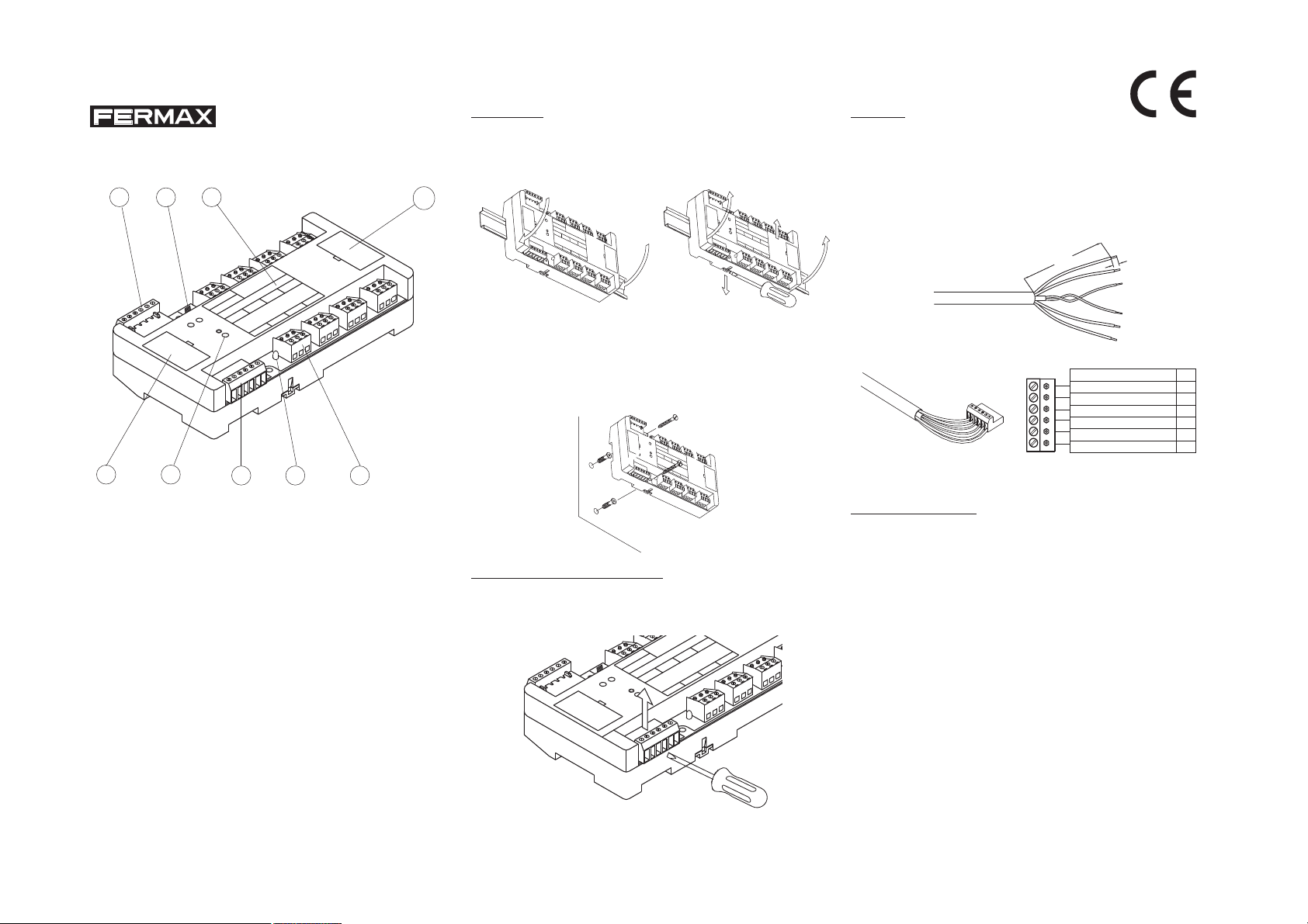
1. Connecteur du câble
BUS pour connecter les
décodeurs suivants,
selon le schéma de
câblage correspondant.
2. Connecteur du câble
BUS des décodeurs
antérieurs ou de l ’Unité
Centrale, selon schéma
de câblage.
3. Bouton PGM (suivre les
instructions du Manuel
de Programmation du
Décodeur).
4. Connecteur de relais.
Brancher selon le
schéma de câblage.
D
M
PG
S
BU
+
2 5 4
SYSTÈME MDS
Guide d’installation du
DÉCODEUR 8 RELAIS
S
LÉ
E
R
E R
E
D
D
O
R
E
EC
D
O
D
C
LA
E
R
N
R
E
5
D2
D1-
8
S
Y
º:
6
R
1
4
S
7
Y
A
L
E
3
/ R
S
E
L
E
2
nc
c
no
nc
c
no
c
no
nc
c
no
26
5. Led indicatrice. Une fois
le système démarré,
elle s’allumera lorsque
le senseur correspondant est activé.
6. Etiquette d’Identification
du Décodeur.
7. Connecteur de
programmation / test
par PC (sous le
couvercle).
9. Déconnexion
d'émergence.
Permet de libérer tous
les relais en cas
d'émergence.
Installation
Le décodeur 8 relais peut s’installer sur rail DIN ou se
visser à la cloison :
Câblage
Réalisez le câblage du décodeur en suivant les
instructions du schéma de câblage correspondant.
* Installation sur rail DIN
9
nc
B
U
S
F
E
R
M
M
A
D
E
I
N
A
S
P
A
X
I
N
R
E
F
.
2
DEC
4
3
0
ODER DE R
D
E
C
RELAYS D
O
P
D
ELÉS
G
E
R
M
ECODER
N
º
:
B
U
5
S
6
R
1
E
L
E
7
S
/
R
2
E
L
A
8
Y
+
S
3
D
1
D
2
4
2
6
n
o
c
n
c
n
o
c
n
c
n
o
c
n
c
n
o
c
n
c
Montage
B
U
S
F
E
R
M
M
A
D
E
I
N
A
S
P
A
X
I
N
R
E
F
.
2
D
4
E
3
C
0
O
D
D
E
E
R
C
D
R
O
E
E
L
R
A
P
D
E
Y
L
S
G
E
É
D
S
R
M
E
N
C
O
º:
D
E
R
B
U
5
S
6
RELES / RELAYS
1
7
2
+
D
1
8
3
D
2
4
2
6
n
o
c
n
c
n
o
c
n
c
n
o
c
n
c
Démontage
n
o
c
n
c
* Dénudation des câbles :
Dénudez le câble sur 10 cm et chaque fil sur 0,5 cm environ. Attention à ne pas abîmer l’enveloppe des câbles.
10 cm
REF. 5918
0,5 cm
* Fixez les connecteurs
* Installation directement sur le mur
Utilisez les chevilles et les vis fournies, pour fixer le
décodeur au mur. Utilisez un foret nº6 pour percez les
trous.
B
U
S
F
E
R
M
M
A
D
E
I
N
A
S
P
A
X
I
N
R
E
F
.
2
D
4
E
3
C
0
O
D
D
E
E
R
C
R
D
O
E
E
L
R
A
P
D
E
Y
L
S
G
E
É
S
R
D
M
E
N
C
O
º:
D
E
R
B
U
5
S
6
R
1
E
L
E
7
S
/ R
2
E
L
A
8
Y
S
+
3
D
1
D
2
4
2
6
n
o
c
n
c
n
o
c
n
c
n
o
c
n
c
n
o
c
n
c
R
E
F
. 5
9
1
8
+
D1
D2
2
Une fois câblés selon le schéma d’installation, montez à
Recommandations
Câblage du Bus de Décodeurs
Couleur des câbles Réf. 5918
Marron
Orange
6
Noir (paire tressée)
Blanc (paire tressée)
Rouge
Bleu
+
-
D1
D2
2
6
* Faîtes très attention à respecter la polarité des câbles.
Le mauvais placement d’un câble empêchera le
Démontage des connecteurs
Utilisez un tournevis pour retirer les connecteurs et pouvoir fixer les câbles facilement.
L
E
R
R
E
E
D
D
O
R
C
E
E
D
O
D
8
S
Y
º:
6
R
1
4
S
7
Y
A
L
E
3
/ R
S
E
L
E
2
nc
c
no
nc
c
no
nc
c
no
26
BUS
FERMAX
PGM
N
I
A
P
S
N
I
E
D
A
M
REF. 2430
E
D
BUS
C
E
D
A
L
E
R
N
R
E
D
O
C
5
D2
D1-
+
décodeur ou toute l’installation de fonctionner, et peut
causer de graves avaries.
* Le décodeur doit toujours être installé en intérieur, à
l’abri de la pluie et de l’humidité.
* Compléter l’étiquette d’Identification du Décodeur,
avec le numéro du décodeur et les numéros de relais
attribués selon le schéma de câblage. Cela facilitera
la programmation et les révisions postérieures.
REMARQUES sur le DÉCODEUR:
- La première adresse doit impérativement être
programmée.
- Ne pas programmer plusieurs sorties avec la même
adresse.
 Loading...