

Page 1

INTERFACE TELEFÓNICO
O
INTERFACE TELEFÓNIC
« TELEPHONE INTERFACE MANUAL »
Ref.1088 - Telephone Interface for ADS systems.
Ref. 4300 - Telephone Interface for 4+N systems.
Technical publication of informative nature edited by FERMAX ELECTRONICA S.A.E.
FERMAX ELECTRONICA S.A.E., in a policy of ongoing enhancement, reserves the right to modify the
contents of this document as well as the features of the products described herein at any time and without
prior notice. Any modifications will be reflected in subsequent editions of this document.
ENGLISH
16
Page 2

INTERFACE TELEFÓNICO
INTERFACE TELEFÓNICO
INDEX
INTRODUCTION ............................................................................................................................................... 4
CONFIGURATION ............................................................................................................................................. 5
TYPICAL SETUP ...........................................................................................................................................5
MIXED SETUP ............................................................................................................................................... 5
SETUP WITH TELEPHONE SWITCHBOARD, CONNECTION IN EXTENSIONS ..................................... 6
SETUP WITH TELEPHONE SWITCHBOARD, CONNECTION ON LINE .................................................. 6
INSTALLATION DIAGRAM - CONVENTIONAL SYSTEM (4+n) ..................................................................... 7
INSTALLATION DIAGRAM - ADS SYSTEM ..................................................................................................... 8
PROGRAMMING INSTALLATION PARAMETERS .......................................................................................... 9
PROGRAMMING EXAMPLE 1 .................................................................................................................. 10
PROGRAMMING EXAMPLE 2 .................................................................................................................. 10
PROGRAMMING USER PARAMETERS........................................................................................................ 11
PROGRAMMING EXAMPLE ..................................................................................................................... 11
OPERATION..................................................................................................................................................... 12
ADDITIONAL OPERATIONS WITH OUTDOOR PANEL ........................................................................... 13
CALL DIVERT FUNCTION.......................................................................................................................... 13
TROUBLESHOOTING ..................................................................................................................................... 14
TECHNICAL FEATURES................................................................................................................................. 15
17
Page 3
INTERFACE TELEFÓNICO
O
INTERFACE TELEFÓNIC
INTRODUCTION
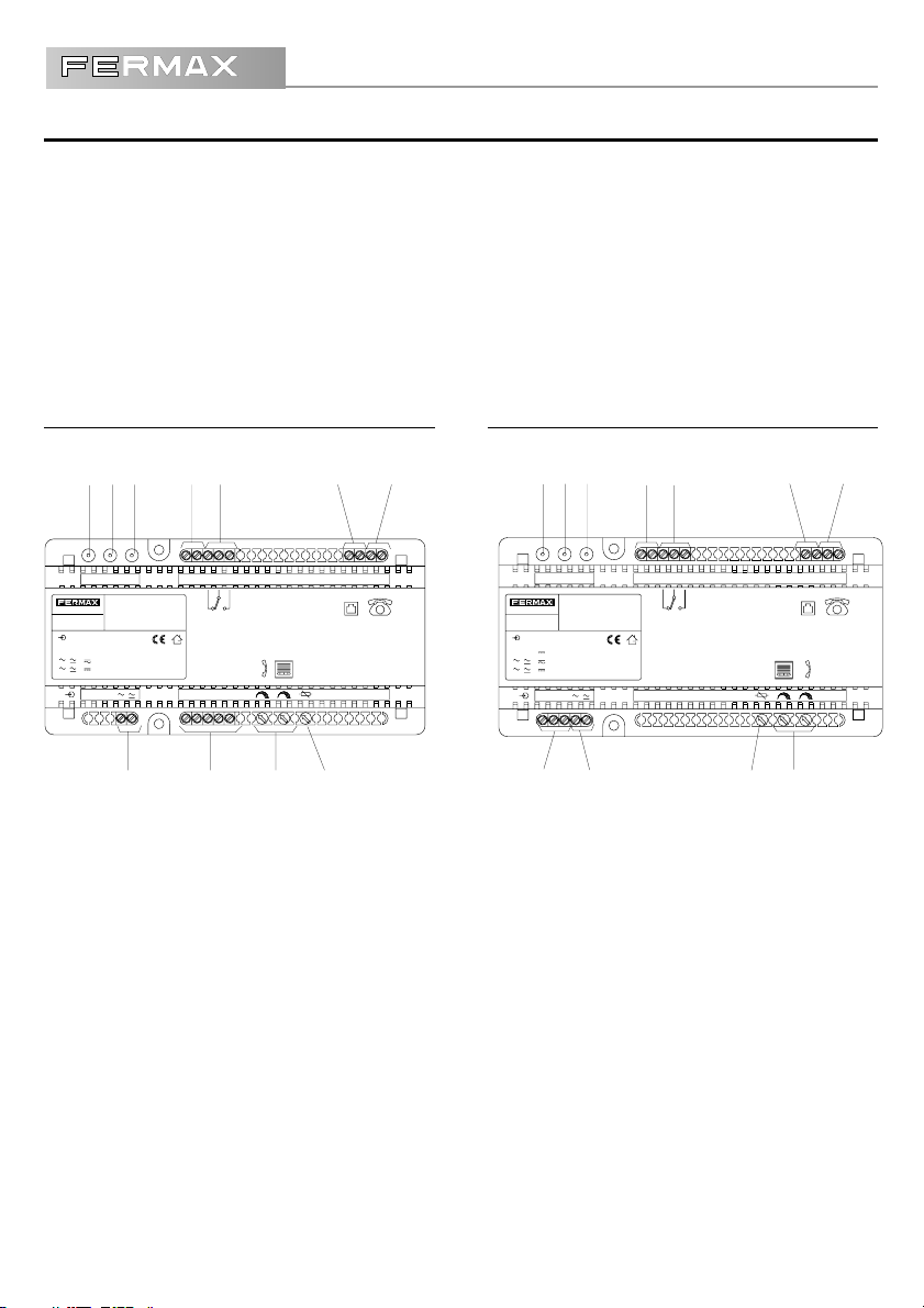
TheTelephone Interface is supplied in two different versions:
- For Conventional 4+N System (Ref.4300)
Compatible with all Fermax conventional system amplifiers (both electronic call and buzzer)
- For ADS System (Ref.1088)
The maximum number of telephones connected to the Telephone Interface to ensure correct operation is 4
(the same as with telephone companies).
Telephone Interface 4+N Ref. 4300 Telephone Interface ADS Ref. 1088
12 3 4 5 697
MADE IN SPAIN
REF. 4300
INPUT
PRG
INTERFACE TELEFONICO 4+N
4+N TELEPHONIC INTERFACE
12 V, 700 mA, 50-60 Hz
12 V, 400 mA
8
NC CUSE PWR D D NO
-
FORWARD
123 46
- VEASE LAS INSTRUCCIONES DE INSTALACIÓN
ANTES DE CONECTAR A LA ALIMENTACIÓN.
- SEE INSTALLATION INSTRUCTIONS
BEFORE CONNECTION TO THE SUPPLY.
AUDIO ADJUST
1011
1- Green LED, in use.
Lights up when Interface is being used and blinks
when divert number is keyed in.
2- Yellow LED, programming.
Lights up when programming mode is entered.
3- Red LED, power.
Lights up when power supply is switched on.
4- Contacts for divert switch
Connect switch here to activate or deactivate call
divert (optional).
12 3 4 5 697
TFLNLN TF
INTERFACE TELEFONICO ADS
MADE IN SPAIN
REF. 1088
INPUT
-+
ADS TELEPHONIC INTERFACE
18 V, 400 mA
12 V, 700 mA, 50-60 Hz
12 V, 300 mA
-
+
L
12
FORWARD
8
- VEASE LAS INSTRUCCIONES DE INSTALACIÓN
ANTES DE CONECTAR A LA ALIMENTACIÓN.
- SEE INSTALLATION INSTRUCTIONS
BEFORE CONNECTION TO THE SUPPLY.
AUDIO ADJUST
10
LNNONCD-DC LN TFTFUSE PRG PWR
5- Relay contacts
6- Telephone line connection (LN,LN)
7- Line output to telephones (TF,TF)
8- Power input
9- Panel/telephone audio adjustments
10- Audio adjustments in divert
11- Door control connection (or panel bus) 4+N
12- Door control connection (or panel bus) ADS
18
Page 4
INTERFACE TELEFÓNICO
INTERFACE TELEFÓNICO
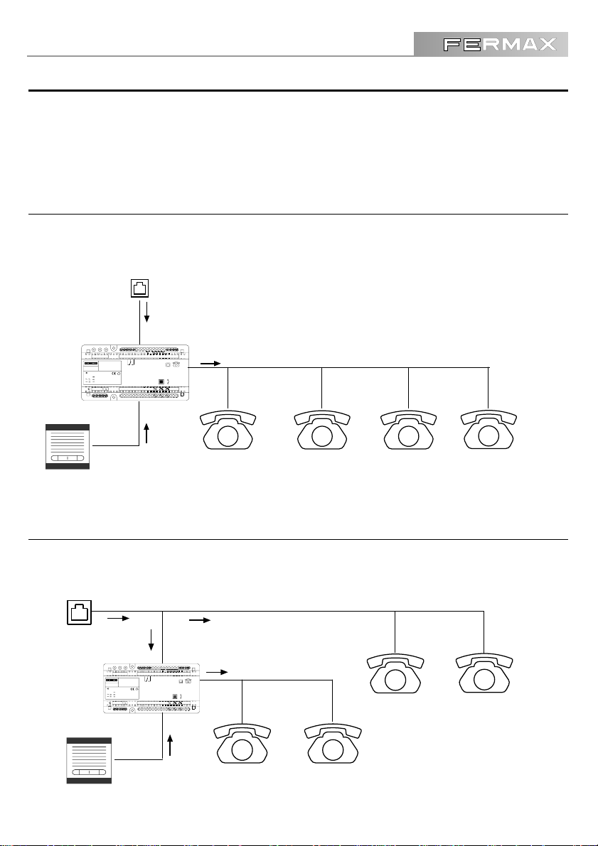
CONFIGURATION
The Telephone Interface enables the house telephones to receive and answer calls from the automatic
porter and it is also possible to divert them out by means of the telephone line.
Here are some examples in block diagram format:
TYPICAL SETUP
All the telephones also carry out electronic door control functions.
RTB
TELEPHONE LINE
INTERFACE TELEFONICO ADS
MADE IN SPAIN
ADS TELEPHONIC INTERFACE
FORWARD
INPUT
-+
18 V, 400 mA
12 V, 700 mA, 50-60 Hz
12 V, 300 mA
- VEASE LAS INSTRUCCIONES DE INSTALACIÓN
ANTES DE CONECTAR A LA ALIMENTACIÓN.
- SEE INSTALLATION INSTRUCTIONS
BEFORE CONNECTION TO THE SUPPLY.
AUDIO ADJUST
LNNONCD-DC LN TFTFUSE PRG PWR
MIXED SETUP
In this example, some telephones perform door control operations and others do not.
RTB
TELEPHONE LINE
INTERFACE TELEFONICO ADS
MADE IN SPAIN
ADS TELEPHONIC INTERFACE
INPUT
-+
18 V, 400 mA
12 V, 700 mA, 50-60 Hz
12 V, 300 mA
LNNONCD-DC LN TFTFUSE PRG PWR
FORWARD
- VEASE LAS INSTRUCCIONES DE INSTALACIÓN
ANTES DE CONECTAR A LA ALIMENTACIÓN.
- SEE INSTALLATION INSTRUCTIONS
BEFORE CONNECTION TO THE SUPPLY.
AUDIO ADJUST
TELEPHONE ONLY
TELEPHONE / DOOR CONTROL
19
Page 5
INTERFACE TELEFÓNICO
O
INTERFACE TELEFÓNIC
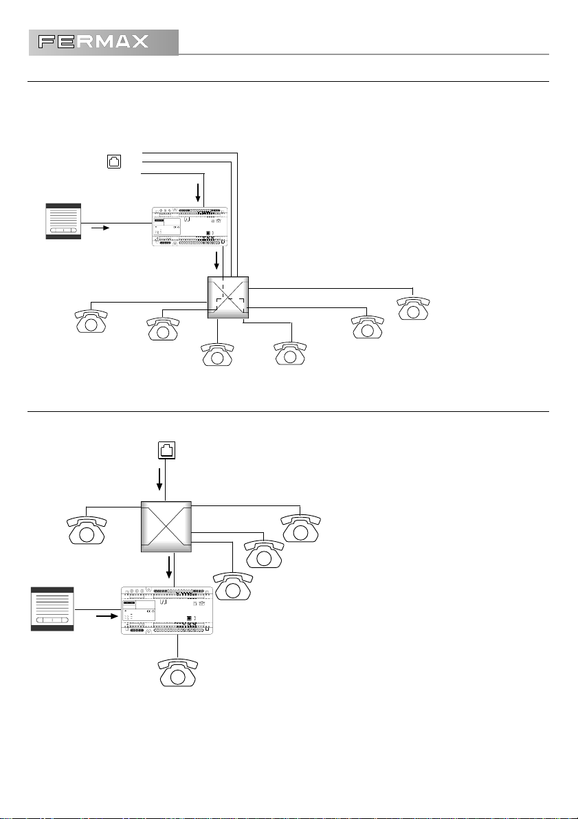
SETUP WITH TELEPHONE SWITCHBOARD, CONNECTION ON LINE
Telephone Interface intercepts the line before it enters the switchboard and so all the extensions depending
on the inbound line will receive the calls from the outdoor panel.
L3
L2
L1
TELEPHONE LINES
RTB
EXAMPLE:
• The Interface intercepts 1 of the 3 telephone lines (L1, L2, L3)
coming into the switchboard.
• The extensions set up to receive outside calls from Line 1 (e.g:
TELEPHONE ONLY
Ext. 1
INTERFACE TELEFONICO ADS
MADE IN SPAIN
ADS TELEPHONIC INTERFACE
INPUT
-+
18 V, 400 mA
12 V, 700 mA, 50-60 Hz
12 V, 300 mA
Ext. 2
TELEPHONE /
DOOR CONTROL
LNNONCD-DC LN TFTFUSE PRG PWR
FORWARD
- VEASE LAS INSTRUCCIONES DE INSTALACIÓN
ANTES DE CONECTAR A LA ALIMENTACIÓN.
- SEE INSTALLATION INSTRUCTIONS
BEFORE CONNECTION TO THE SUPPLY.
AUDIO ADJUST
PABX
Ext. 3
TELEPHONE ONLY
Ext. 2 and Ext. 4), can also act as a door control .
Ext. 6
TELEPHONE ONLY
Ext. 5
TELEPHONE ONLY
Ext. 4
TELEPHONE / DOOR
CONTROL
SETUP WITH TELEPHONE SWITCHBOARD, CONNECTION IN EXTENSIONS
Telephone Interface intercepts the telephone line at an outbound switchboard extension.
RTB
TELEPHONE LINE
PABX
Ext. 1
Ext. 5
Ext. 4
INTERFACE TELEFONICO ADS
MADE IN SPAIN
ADS TELEPHONIC INTERFACE
INPUT
-+
18 V, 400 mA
12 V, 700 mA, 50-60 Hz
12 V, 300 mA
LNNONCD-DC LN TFTFUSE PRG PWR
FORWARD
- VEASE LAS INSTRUCCIONES DE INSTALACIÓN
ANTES DE CONECTAR A LA ALIMENTACIÓN.
- SEE INSTALLATION INSTRUCTIONS
BEFORE CONNECTION TO THE SUPPLY.
AUDIO ADJUST
Ext. 3
EXAMPLE:
• Interface intercepts an outbound switchboard extension Ext. 2.
• Telephones depending on this extension will perform door control
functions.
Ext. 2
TELEPHONE / DOOR CONTROL
√ √
√
IMPORTANT NOTES:
√ √
• The Telephone Interface will only accept tone dialling .
• For use in ISDN or ADSL lines the necessary filters or adaptors must be installed.
20
Page 6

INTERFACE TELEFÓNICO
INTERFACE TELEFÓNICO
INSTALLATION DIAGRAMS - CONVENTIONAL SYSTEM (4+n)
APARTMENT
1
4
3
6
2
GENERAL INSTALLATION
6321
RTB
DIVERT SWITCH(OPTIONAL)
TFLNLN TF
NC CUSE PWR D D NO
-
PRG
ANTES DE CONECTAR A LA ALIMENTACIÓN.
BEFORE CONNECTION TO THE SUPPLY.
- VEASE LAS INSTRUCCIONES DE INSTALACIÓN
- SEE INSTALLATION INSTRUCTIONS
FORWARD
INTERFACE TELEFONICO 4+N
4+N TELEPHONIC INTERFACE
INPUT
MADE IN SPAIN
REF. 4300
12 V, 700 mA, 50-60 Hz
12 V, 400 mA
AUDIO ADJUST
123 46
+ CALL WIRES
6321
GENERAL INSTALLATION
SEC. 12Vac
MADE IN SPAIN
Vac
PRIM
REF. 8980
12 Vac - 1A
• You can place the Telephone Interface at any point of the conventional installation connecting cables 1, 2, 3, 6 and 4 (call )
NOTE:
21
Page 7

INTERFACE TELEFÓNICO
O
INTERFACE TELEFÓNIC
INSTALLATION DIAGRAM - ADS System
APARTMENT
-
+
L
22
RTB
DIVERT SWITCH (OPTIONAL)
+L
-
GENERAL INSTALLATION
LNNONCD
ANTES DE CONECTAR A LA ALIMENTACIÓN.
BEFORE CONNECTION TO THE SUPPLY.
- VEASE LAS INSTRUCCIONES DE INSTALACIÓN
- SEE INSTALLATION INSTRUCTIONS
AUDIO ADJUST
FORWARD
DC LN TFTFUSE PRG PWR
-
18 V, 400 mA
12 V, 700 mA, 50-60 Hz
INPUT
-+
12 Vac - 1A
12 V, 300 mA
REF. 8980
L
+
INTERFACE TELEFONICO ADS
ADS TELEPHONIC INTERFACE
MADE IN SPAIN
REF. 1088
SEC. 12Vac
MADE IN SPAIN
Vac
PRIM
+
L
-
GENERAL INSTALLATION
• The Telephone Interface can be placed at any point of the ADS installation, intercepting the 3 cables ( +, - , L )
NOTE:
Page 8

INTERFACE TELEFÓNICO
1
2
4
3
5
6
7
8
9
*
0
#
A
B
INTERFACE TELEFÓNICO
PROGRAMMING INSTALLATION PARAMETERS
Installation Parameters are configured when the Interface is installed and are not usually modified
afterwards. The following table shows some of these parameters.
Digit Parameter Value
House number (ADS Number)
0
Number the panel identifies Interface with.
Open door timing
2
Time door release mechanism is activated.
Relay timing
5
Time relay is activated.
Ring pattern(Call type)
6
Number of tones heard at telephone when call is received.
1-199
1-200
1-60
1-10
System
ADS
4+N
BOTH
BOTH
When entering the Open Door Timing, the Relay Timing or Ring Tone, we take the following table into
account:
Parameter Value entered Equivalent time
Open door timing
Relay timing
Ring tone
N (1....200)
N (1......60)
N (1.....10)
t= N / 4 sec.
t= N / 2 sec.
t=N sec.
Default
4 sec.
2.5 sec.
1 sec.
The system can be programmed from any telephone connected to the Interface. To do so:
1- Unhook the telephone handset you are going to program the Interface from.
Dialling tone sounds.
2- Press the ‘#’ key.
Now the PRG LED lights up and the dialling tone stops.
3- On the telephone, press the digit corresponding to the parameter you want to program.
4- Use the keypad to input the new value.
The green LED lights up every time you press a key.
5- Press ‘#’ again to exit programming mode.
Or wait 30 seconds without pressing any keys.
√ √
NOTES:
√
√ √
• The Telephone Interface must be connected to the telephone line for programming.
• The Ring Pattern may be changed to make it easier to distinguish when a door control call is received
and when it is a normal telephone call.
23
Page 9

INTERFACE TELEFÓNICO
O
1
2
4
3
5
6
7
8
9
*
0
#
A
B
INTERFACE TELEFÓNIC
Here are a couple of practical examples of how to program the Interface installation parameters:
PROGRAMMING EXAMPLE 1
To program the Relay Timing; take the following steps:
1- Unhook the telephone handset you are going to program the Interface from.
2- Press the ‘#’ key. The PRG LED will light up and the dialling tone stops.
3- Enter the digit corresponding to the parameter you wish to program.
In this example it would be 2
4- Key in the new parameter value. To introduce this value, consult the table on the
previous page, where:
If you want an opening time of 5 seconds, select an N value, so that:
t = 5 seconds N = t*4
N = 20
The maximum door open timing we can set corresponds to the maximum N:
N = 200 t = N / 4 50 seconds
5- Press ‘#’ again to exit programming mode or wait 30 seconds without pressing any keys.
To program the Open Door Timing or Ring Pattern, proceed in the same way and assign N the
value needed to obtain the desired timing.
PROGRAMMING EXAMPLE 2
Let’s see how to program the ADS number:
This only needs to be done if you have Telephone Interface Ref. 1088.
- Proceed with the first 2 steps as in the example above. In step 3, key in 0, (digit corresponding to the
ADS Number parameter as appears in the table on the previous page).
- Step 4, enter the parameter value (ADS telephone nº between 1 and 199)
You must enter the same number as the FERMAX electronic door control system .
- Press ‘#’ to exit programming mode.
You also exit programming mode after 30 seconds without pressing any key.
24
Page 10

INTERFACE TELEFÓNICO
1
2
4
3
5
6
7
8
9
*
0
#
A
B
INTERFACE TELEFÓNICO
PROGRAMMING USER PARAMETERS
The User Parameters are those that may be modified most often in line with the user’s needs. The
following table shows what these are:
Digit Parameter Value
Divert Telephone.
3
Telephone number calls will be diverted to.
Call divert activation.
7
Lets you activate the divert from the telephone.
Call divert deactivation.
8 BOTH
Lets you deactivate the divert from the telephone.
√ √
√
NOTES:
√ √
TELEPHONE
NUMBER
NO
NO
System
BOTH
BOTH
• Maximum length of the divert telephone is 16 figures.
• It is not necessary to enter any value for divert activation or deactivation.
• It is possible to activate or deactivate the divert by means of an additional switch (see
installation diagrams).
PROGRAMMING EXAMPLE
To program the divert Telephone, proceed as follows:
1- Unhook the telephone handset you want to program the Interface from.
2- Press the ‘#’ key. The PRG LED will light up and the dialling tone stops.
3- Key in the digit corresponding to the parameter you wish to program.
In this example it would be 3
4- Key in the new parameter value, in this case the telephone number
you want to divert the door call to. For example: 612 345678
5- Press ‘#’ again to exit programming mode or wait 30 seconds without pressing any keys.
The telephone number to which the call will be diverted has now been programmed (in this case a mobile
phone). Remember that the maximum length of the divert number is 16 digits.
25
Page 11

INTERFACE TELEFÓNICO
O
INTERFACE TELEFÓNIC
OPERATION
• If the telephone is not in use, a characteristic ring is generated until answered or
30 seconds have elapsed. When you answer you have 90 seconds to
communicate with the door intercom. Once communication is established, you
can carry out a series of operations, such as:
- Open the door by pressing ‘5’ on the telephone keypad.
- Activate a relay by pressing key ‘7’.
• If the telephone is being used, a tone is generated in the house telephone earpiece,
indicating a call from the door intercom. The call may be taken in two different ways:
- Without picking up the telephone: press key ‘4’. The telephone call is not lost, but
remains on hold until key ‘4’ is pressed again.
- Hanging up the telephone, the phone will ring until the call is answered or 30 seconds
have elapsed.
• While you are answering a call from the door intercom, you might
receive a telephone call. In this case an alert tone is generated in the
earpiece and the call may be answered in two ways:
- Press key ‘4’ without hanging up. The door intercom call
terminates automatically at this point.
- Hang up the phone. The normal telephone ring tone will
sound.
• If you wish to set up audio contact with the street from the house telephone
without having been called previously, proceed as follows:
- Press ‘*’ and ‘1’, ‘2’, or ‘5’ (ADS system: 1 main pannel, 2 secondary pannel;
4+N system, 5). Now the interface will make a call to your telephone.
- If it is off the hook (the most logical situation, as you have just dialled), a tone
sounds in the earpiece indicating a call waiting. All you have to do is hang
up or press 4 to receive the call.
26
Page 12

INTERFACE TELEFÓNICO
INTERFACE TELEFÓNICO
ADDITIONAL OPERATIONS WITH OUTDOOR PANEL
If communication with the outdoor panel has not been established, you can take the following steps:
- Call the guard unit (if there is one) by pressing ‘*’ and ‘4’ consecutively.
- In ADS systems you can activate panel 1 by pressing ‘*’ ,‘1’ and panel 2 (if there is one) by pressing
‘*’ ,‘2’ (see note)
- In Conventional 4+N systems, you can connect outdoor panel audio by pressing ‘*’,‘5’ (see note below)
as long as the system is not Secret, in which case nothing will be heard.
CALL DIVERT FUNCTION
Whenever you wish, the call divert lets you transfer the call made by a visitor from the outdoor panel and
answer it from any fixed or mobile telephone (as long as tone dialling is used) just as if you were at home.
INTERFACE TELEFONICO ADS
MADE IN SPAIN
ADS TELEPHONIC INTERFACE
INPUT
-+
18 V, 400 mA
12 V, 700 mA, 50-60 Hz
12 V, 300 mA
LNNONCD-DC LN TFTFUSE PRG PWR
FORWARD
- VEASE LAS INSTRUCCIONES DE INSTALACIÓN
ANTES DE CONECTAR A LA ALIMENTACIÓN.
- SEE INSTALLATION INSTRUCTIONS
BEFORE CONNECTION TO THE SUPPLY.
AUDIO ADJUST
TELEPHONE
NETWORK
The divert may be activated or deactivated in two ways:
- By means of a pushbutton connected between Interface terminals D and D
- Entering programming mode and pressing the corresponding digit, as shown in the User Parameters
section.
To check if the call divert function is activated, pick up the house telephone and you will hear a special tone.
√ √
√
VERY IMPORTANT NOTE:
√ √
• When a call is received on the divert telephone, to end the call press ‘8’ and then hang up the
phone.
• If you do not end the call by pressing ‘8’ the Interface will keep the line busy until a period of 90
seconds has elapsed.
• The divert telephone must have tone dialling. Door opening and relay activation operations
are done in the same way as from the house phone.
27
Page 13

INTERFACE TELEFÓNICO
O
INTERFACE TELEFÓNIC
TROUBLESHOOTING
INTERFACE DOES NOT WORK
• IS THE RED INTERFACE LED LIT ?
- No: Make sure the equipment is receiving power and that the source is connected.
- Yes: Check the door control connections and that the telephone has tone dialling.
• IS THE INTERFACE CONNECTED TO A SWITCHBOARD EXTENSION?
- Yes: It is possible that the switchboard will only accept devices from the same
manufacturer or with different control standards.
SOUND VOLUME IS VERY LOW
• Is THE CALL DIVERTED ?
- No: Use the two Interface potentiometers to regulate the audio level (see page 4)
- Yes: With the call diverted, adjust the audio level with the divert adjustment potentiometer (see page 4).
THE TELEPHONE OR OUTDOOR PANNEL SOUNDS NOISY
• Check that power supply adapter is connected to ground (depends on model) .
SYSTEM IS BLOCKED
• Deactivate the divert by pressing # 8 # with the phone off the hook.
UNABLE TO PROGRAM THE INTERFACE
• Check that telephone line is correctly connected.
28
Page 14

INTERFACE TELEFÓNICO
INTERFACE TELEFÓNICO
TECHNICAL FEATURES
Telephone Interface Power Supply
18V DC ± 10 % or 12V DC ± 10 % 300 mA standby
400 mA in communication
12V AC ± 10 % 600 mA standby
700 mA in communication
Operating Temperature
0 - 60 ºC Hr 90 %
Connectors:
Ref. 1088 / ADS System
+, - : 18 Vdc supply
L: ADS system line L
Ref. 4300 / 4+N System
1: door release
2: audio from 4+N system
3: mass
4: call
6: audio to 4+N system
+, -: supply 12 Vdc or Vac
Telephone lines
TF, TF: telephone pair from house
LN, LN: telephone pair from central switchboard
Relay
NO, C, NC Potential free contacts
Max. current: 4 A (40 V)
29
 Loading...