

Fermator VCI-VF5A.CD0 Series, VCI-VF5A.CI0 Series, VF5 Assembly Manual
ENG
AUTOMATIC DOORS FOR LIFTS
Assembly manual.
Automatic horizontal sliding car door.
Component: VF5 Electronic Module.
MAN-MMCAENGV5TC-10.2017
AUTOMATIC DOORS FOR LIFTS
Opcional
e
0
C
0
Optional
N
Ref. WCE-VFCE.C0000
OBSTRUCTION
OBSTRUCCIÓN
ESTADO
STATUS
INTELIGENTE / MASTER
ESCLAVO / SLAVE
FOTOCÉLULA
PHOTOCELL
SAFETY
FUERZA
OPEN SPEED
VELOCIDAD ABRIR
5m :Ref.CFT-FC00.C0000
3m :Ref.CFT-FCDM.C0000
CLOSED
ABIERTA
CERRADA
EMITTER
RECEIVER
RECEPTOR
OPEN
FOTOCÉLULA / PHOTOCELL
PUERTO SERIE
13
123
SUPPLY
L2
L1
230 V. AC
GND
ALIMENTACIÓN
THE COVER
DO NOT OPEN
Ref. VCI-AESB.C00EE
NO ABRIR LA TAPA
L1’
GND
L2’
567
SALIDA VF4+
VF4+ OUTPUT
EMISOR
+12 V COM
REABRIR / RE-OPEN
PRIORITY INPUTS
ENTRADAS PRIORITARIAS
SEÑAL DE PISO / FLOOR LEVEL
CERRAR LENTO / SLOW CLOSE
SERIAL PORT
CERRAR
VELOCIDAD
CLOSE SPEED
the door
la puerta
AUTOAJUSTE
Push to calibrate
Pulsar para ajustar
AUTOADJUSTMENT
door
TEST
verificar
Pulsar para
Push to check the
66
RELLANO PISO
LANDING FLOOR
EMERGENCIA
ALIMENTADOR DE
CONNECTIONS
29
28
67
BATERIA
BATTERY
FUSE 20A (yellow / amarillo)
SUPPLIER
EMERGENCY
BAT
ON
ESTADO
STANDBY
12 V COM
FLOOR / PISO
1
CONTROL VF4+
26
23
ON
INPUTS
OFF2
ENTRADAS
12 V 2 Ah
2
1
OFF
ON
Ref. VCP-VFCP.C00
2
_
~
15...250 V
_
~
Abrir / Open
Cerrar / Close
15...250 V
MANUAL
AUTOMATIC
AUTOMÁTICA
LANDING DOOR
PUERTA RELLANO
1 ENTRADA
1 INPUT
2 ENTRADAS
2 INPUTS
ASYNC
PM
ENCODER
VCI-VF5A.CI0
Ref. VCI-VF5A.CD0
NO ABRIR LA TAPA
DO NOT OPEN THE COVER
?
Derecha / Right
QCI.VF5A.CD0EE
0
OUT +12 V
CERRAR
CLOSE
MOTOR
INPUTS
ENTRADAS
100...230V AC / DC
0 V
COM
ABRIR
OPEN
SUPPLY
ALIMENT.
.
f. PMT-PM
Ref. PMT-PM00.C0000
R
VF5
AUTOMATIC DOORS FOR LIFTS
1
O
N
234
O
F
F
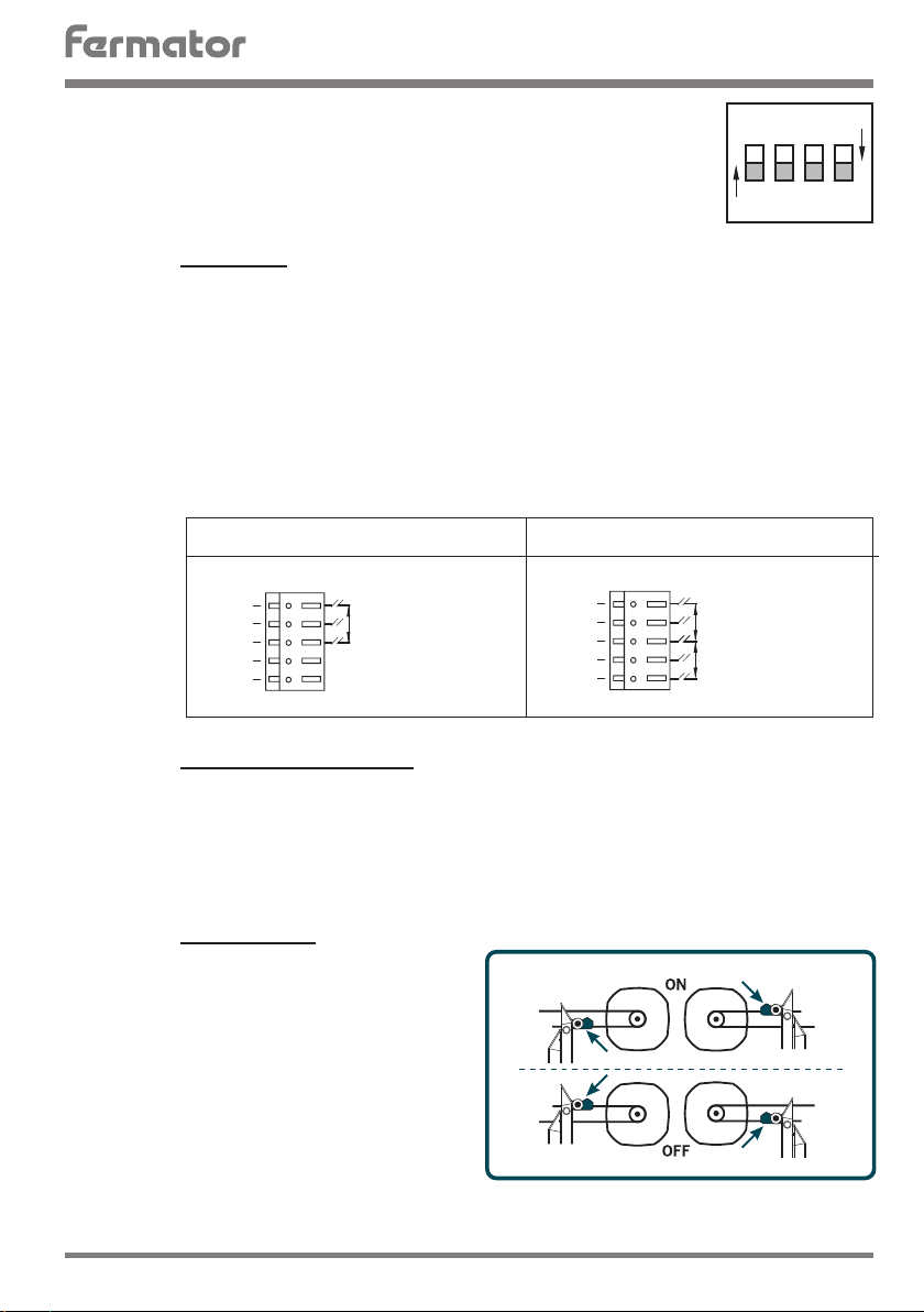
The VF may be programmed using the DIP switches on the front of the unit. If any
Com
0 V
12 V
8
9
10
11
12
Com
0 V
12 V
8
9
10
11
12
change is made to any of the above switch selections, the main supply of the VF 5
unit MUST be switched OFF and ON again to read the new programming.
The switches functions are:
1 1 & 2 Inputs.
ON: 1 Input.
The door control unit will be controlled by a single input. Any voltage between 12 V DC to
60 V DC or door remains opened. When it activates the door close. Open input is not used.
OFF: 2 Inputs.
The door control module will be controlled by two independent inputs. Any voltage between 12 V DC to 60 V DC or 100 V AC to 230 V AC applied between terminals 8 & 10 will
cause the doors to close. And bet ween terminals 10 & 12 will cause the doors to open.
In the absence of a signal, the doors will remain static. If both inputs are applied then the
open signal has priority.
PROGRAMMING
Close
Open
2 Automatic/ Semiautomatic.
ON: Automatic.
Operators with skate (automatic landing). In this case a special movement is made for
locking and unlocking the skate.
OFF: Semiautomatic.
Operators without skate (Semiautomatic landing door)
3 Rotation sense.
ON: Lock at the picture:
-Skate xed on the top side of the belt
and the motor on the right side.
-Skate xed on the bottom side of the
belt and the motor on the left side.
OFF:Lock at the picture:
-Skate xed on the bottom side of the
belt and the motor on the right side.
-Skate xed on the top side of the belt
and the motor on the left side.
VF5
1 INPUTS
Without Voltage
0 V
OPEN
With Voltage
12 V DC...250 V DC,
100 V AC..230 V AC
CLOSE
Close
Open
2 INPUTS
Voltage
12 V DC...60 V DC,
100 V AC...230 V AC
CLOSE
Voltage
12 V DC...250 V DC,
100 V AC...230 V AC
OPEN
3
AUTOMATIC DOORS FOR LIFTS
N
L
230 V
5
6
7
12
11
10
9
8
12
11
10
9
8
PROGRAMMING
4 Master and Slave.
ON: Ma ster.
The door control unit will execute instructions directly. Example: photocell activation will
cause the doors to re-open immediately without control of the door control unit.
OFF: Slave.
There is no automatic reopen movements. The doors will only react to instruction given
by the main lift controller. Example: with the photocell activated the unit will send a signal
to the main lift controller via the PHOTOCELL output (36, 37, 38). Then, the main lif t
controller must remove the close signal and put the open signal.
POWER INPUTS
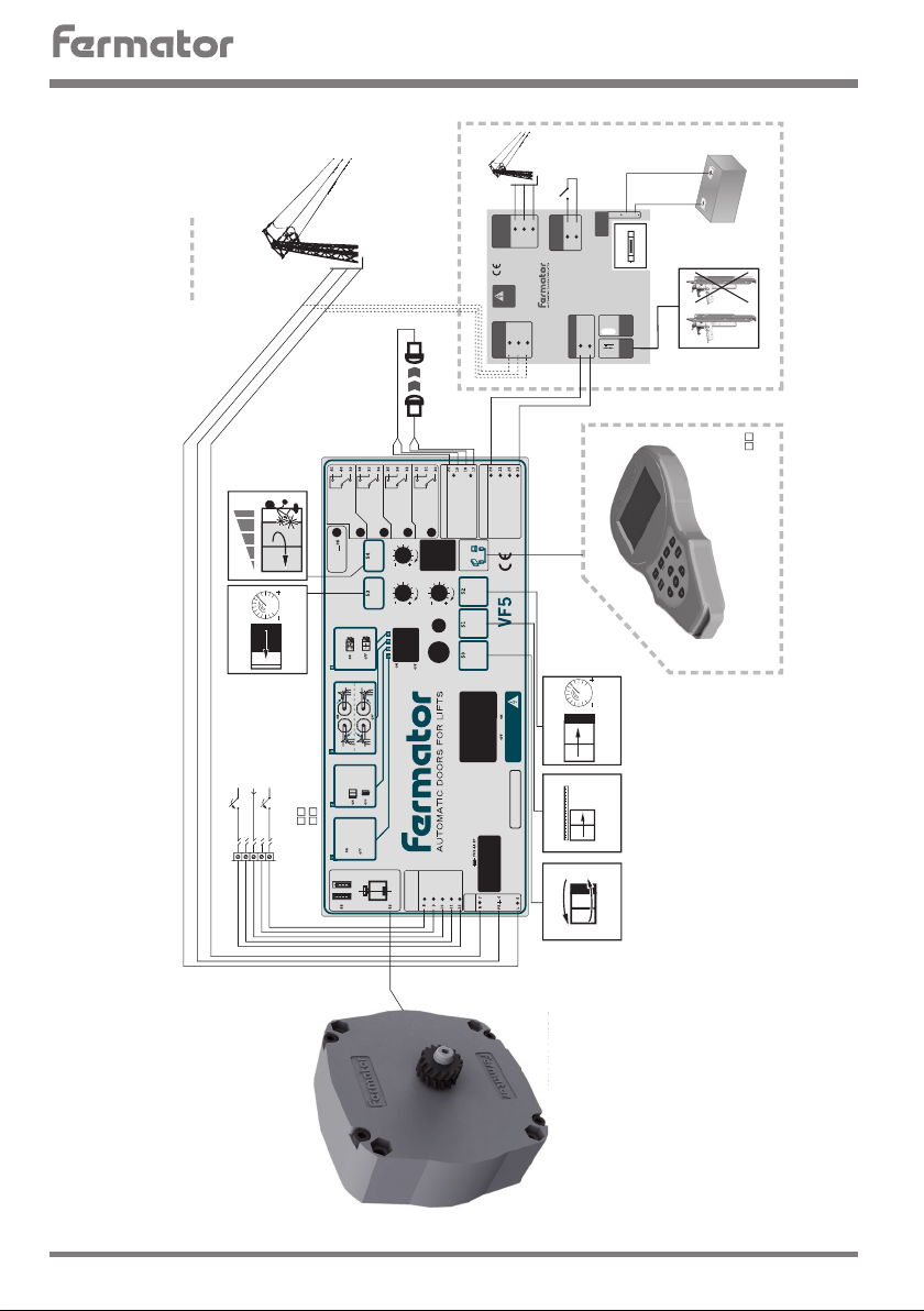
5 / 6 / 7 230 Volts single phase AC.
POWER INPUTS CONNECTIONS
The circuit has been designed to operate on a
mains supply of 230 V AC (+10%,-15%, 50 or 60
Hz). The unit will consume approx 1 Amp from
the supply.
It is important that the Door Operator Module
has a GOOD EARTH CONNECTION.
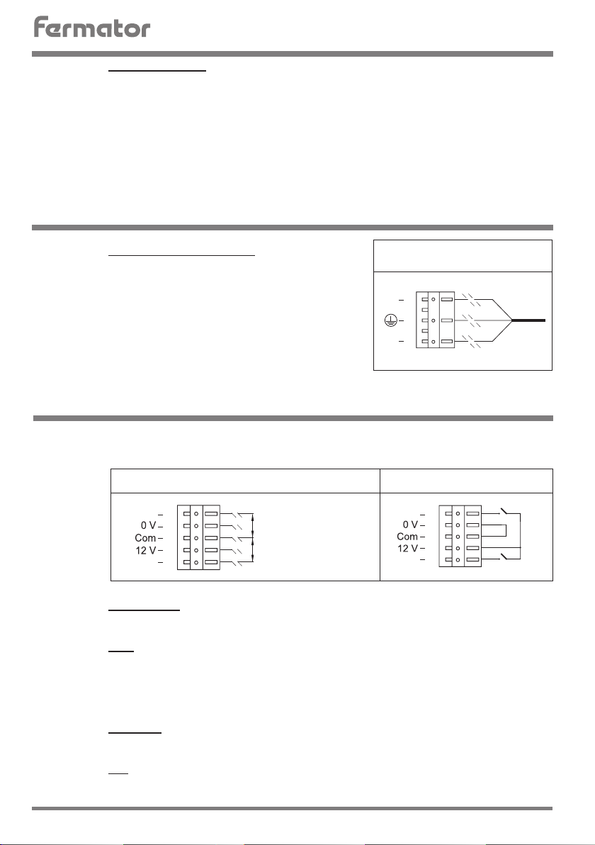
CONTROL INPUTS
The circuit can work with external voltage inputs or internal voltage input
(voltage free contact).
EXTERNAL VOLTAGE INPUTS
Voltage
Open
Close
12 V DC...60 V DC,
100 V AC...23 0 V AC.
OPEN
Voltage
12 V DC...60 V DC,
100 V AC...23 0 V AC.
CLOSE
8 Close signal.
This signal is used for ordering to close the door.
9 12 V.
Isolated 12 V output available to control the door via a voltage free contact.
Features are:
a)This supply must only be used for this purpose.
b)This contact must be isolated from any other power supply.
INTERNAL VOLTAGE INPUTS
Open
Close
OPEN
CLOSE
10 Common.
Is the reference used for the opening and closing signal.
11 0 V.
Is the opposite pole to 12 V, in the case of using internal voltage it should be connected
4
to common input.
VF5
AUTOMATIC DOORS FOR LIFTS
CONTROL INPUTS
20
19
18
17
26
21
25
23
12 Opening Signal.
Is a signal that orders the door to open. The tension to apply could be from 12 V DC to 60
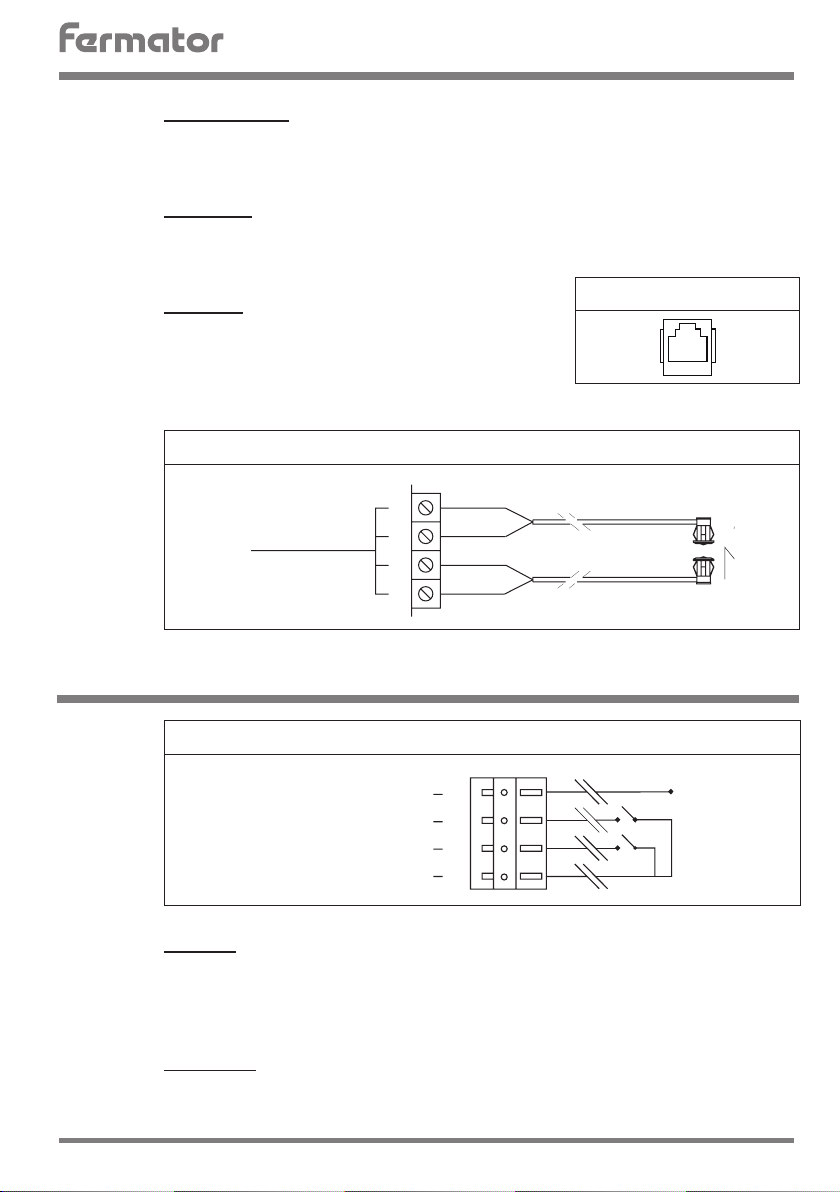
13 Serial Port.
The serial port is used to connect with external devices like the diagnostic console,
17 / 18 / 19 / 20 Photocell.
One of the most relevant characteristics of this control
V DC or 120 V AC to 230 V AC, with an external supply between this input and common
(10).
in t e r f a c e s and fu t u r e exp a n s ion dev i c e s. Opera t i n g spee d 1.200 Baud pe r sec ond, cu r r e nt
loop. It is used a RJ11 connector (phone jack connector).
SERIAL PORT CONNECTION
is the optional incorporation of the Fermator photocell.
It is composed by a emitter and receptor infrared.
CONNECTION OF THE PHOTOELECTRIC DETECTOR
PHOTOCELL
(+) White
(-) Black
(-) Black
(+) White
Green
Yellow
OTHER INPUTS
CONNECTION OF THE «OTHER INPUTS»
FLOOR LEVEL
RE-OPEN
SLOW CLOSE
+ 12 V COM
21 Re-open.
This signal is used for installing the cabin door switch or an external barrier.
In order to active this signal, connect the re-open input (21) with the +12 V (23). Use
23 + 12 V Com.
This terminal is used for giving with an isolated contact a reopening order or a slow closing.
VF5
voltage free contacts. The reopening signal has priority over the closing signal.
Always use voltage free contacts and usually open.
Receiver
Emitter
5
 Loading...