

Page 1
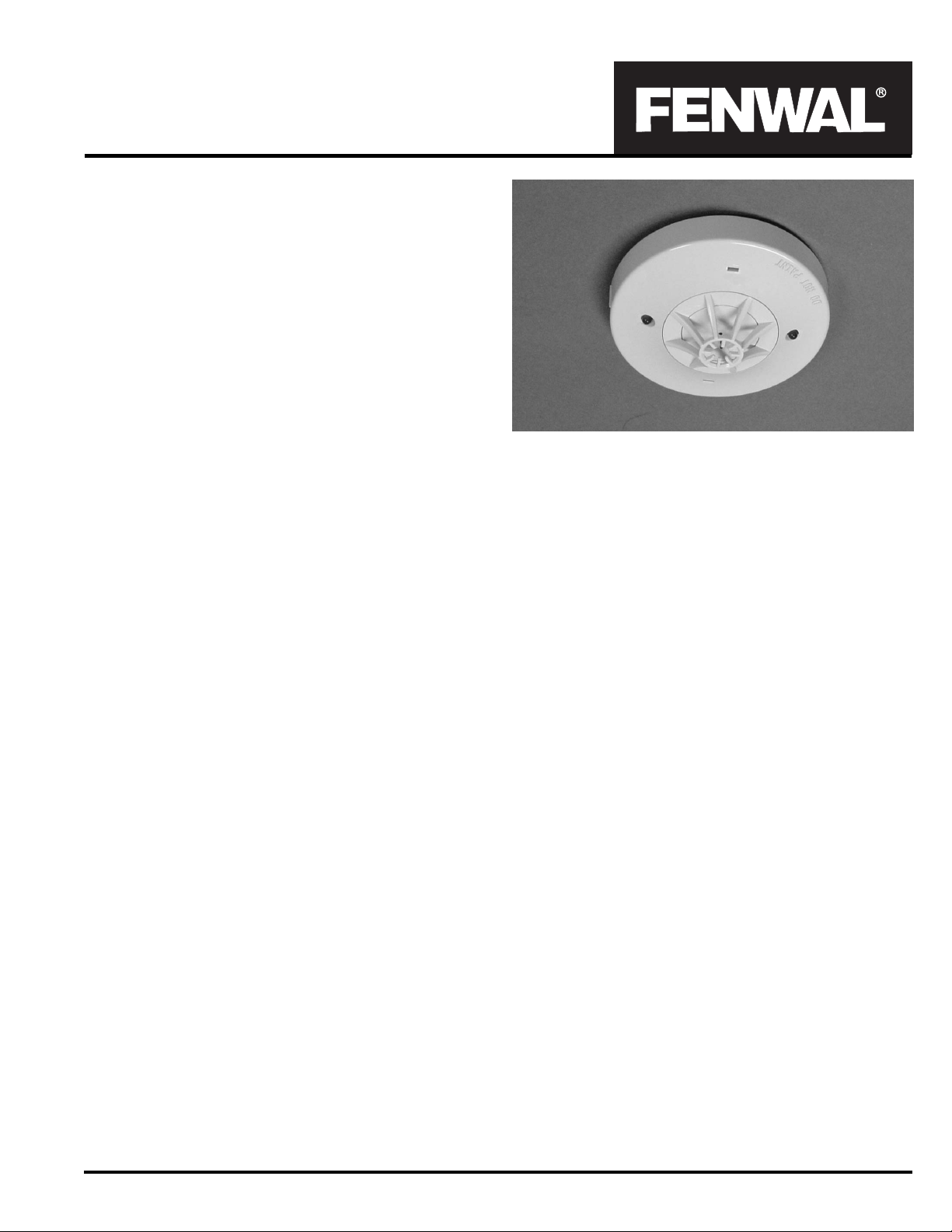
Electronic Heat Detectors
Models THD-7052 & THD-7053
70.03
FEATURES
Approvals/Listing
US and Canadian UL Listed (cULus)
FM Approved
CSFM Approved
NYC MEA Accepted (pending)
Thermistor based Heat Detection
Nominal Sensitivity
THD-7052: 135
o
F (8.3oC) per minute Rate-Of-Rise
15
THD-7053: 135
Wide Range of Input Voltage 10.2 to 36.8 VDC
Low Current design
Dual Response LEDs allow 360-degree viewing
Trouble Indication
Low Profile Appearance using Surface Mount Technology
Electrically and Mechanically Compatible with all Fenwal
Smoke and Electronic Heat Detectors and Bases
Interchangeable 2-Wire and 4-Wire Bases
Universal Relay Modules
Non Polarized
Locking Feature for Vandal Resistance
EMI and RFI Resistant
DESCRIPTION
The Fenwal Models THD-7052 and THD-7053 are thermistorbased electronic Heat Detectors with a 135oF (57oC) Fixed
Temperature set point. In addition, the Model THD-7052 has a
Rate-Of-Rise of temperature detection feature rated at 15oF (8.3oC)
per minute. Both detectors have advanced solid-state, low-voltage,
surface-mount circuitry and are designed for 2-Wire and 4-Wire
installation using the appropriate Detector base. The detectors
are designed for Open Area Protection (UL 521) and may be
installed in systems intended for Releasing Device Service through
use of a compatible Fire Alarm Control Panel
Two Red Light Emitting Diodes are located diametrically opposite
each other so as to allow 360-degree viewing. Both LEDs
continuously indicate the operating condition of the Detector. During
standby, the LEDs flash once every six seconds. During alarm,
both LEDs light steady at full brilliance. A double flash every six
seconds indicates a detector with a thermistor trouble. An optional
base is available to provide remote LED function. A unique gated
output circuit design provides improved stability and transient suppression. Special signal processing techniques verify the presence
of smoke before the detector
The detector head is installed into the base with a simple twistlock action. A locking feature is provided for vandal resistant security. Detector base options are available to. provide for auxiliary
test, indication and/or control functions
o
F (57oC) Fixed Temperature w/
o
F (57oC) Fixed Temperature
will alarm.
Effective: January 2006
Optional bases are available for supplementary 2-wire or 4-wire
relay functions. The Model THD-705x Heat Detectors may be interchanged with other Fenwal Series CPD-705X Ionization and
Series PSD-715X Photoelectric Smoke Detectors when using
multifunction base configuration.
TECHNICAL SPECIFICA TIONS
Table 2 lists the Technical Specifications for Models THD-7052
and THD-7053 Heat Detectors.
CONTROL UNITS
The Models THD-7052 and THD-7053 Detectors are designed
for operation with control units and releasing devices having specific voltage and current characteristics that are compatible with
the detector circuitry. The Detectors are compatible with the
Fenwal control units and interface modules listed in Table 1.
Please refer Fenwal Document 70.63 for UL Compatibility Listings with Fire Alarm Panels manufactured by others.
DETECTOR BASE OPTIONS
The Models THD-7052 and THD-7053 Detectors can be used
with the detector base options and accessories in Tables 3 and
4. Various base options are available to provide auxiliary relay
and/or remote indication and remote test feature.
SP ACING (OPEN AREA LOCA TION)
For UL/ULC applications, the Model THD-7052 and THD-7053
Detectors are listed to be installed on 70 foot (21.3 m) centers,
typically on smooth ceilings up to 15 feet (4.6 m) high and will
operate with minimum air circulation. Resultant maximum 4,900
square foot (455.2 m2) spacing may be used as a reasonable
guide for comparable applications.
For FM applications, the listed spacing is 35 feet (10.7 m) centers. Where special conditions exist (ceiling obstructions, etc.),
reduced spacing must be used to achieve adequate protection.
For additional information, consult the Fenwal Automatic Fire Detection Application Engineering Manual MC-402, NFPA-72 and
the local Authority Having Jurisdiction.
Page 2
WIRING DIAGRAMS
For detailed wiring diagrams with Fenwal 2 and 4-wire bases,
please refer Fenwal Document 70.104.
INSTALLATION
Detector bases are directly mounted on the electrical junction
boxes (3", 3.5" and 4" octagonal, 3" round or 4" square) without
the need for any mechanical adapter required. Refer Fenwal
Document 70.104 for additional details.
The detector bases also include a locking feature that prevents
removal of the detector without use of a tool.
TESTING AND MAINTENANCE
Testing shall be performed upon installation of the detector and
once a year thereafter as stated in NFPA-72 latest edition. All
alarm signal devices, releasing devices, and extinguishing
systems should be disengaged before the test is performed and
re-engaged at the conclusion of testing. Detectors may be tested
using a low power heat gun per instructions detailed in Fenwal
Document 70.104. Failure to alarm in this test indicates a detector
requiring service.
The recommended requirement for detector maintenance consists
of an annual cleaning of dust from the detector head by using the
suction of a vacuum cleaner. Cleaning programs should be geared
to the individual environment in conformance with NFPA 72.
CAUTION
!
Do not attempt disassembly of the factory sealed
detector. This assembly is sealed for your protection
and should not be opened for servicing. Opening of
the detector will void its warranty.
SP ARE P ARTS
The Model THD-7052 and THD-7053 Detectors are factory repairable only and have no field serviceable spare parts. No field
repair should therefore be attempted. For service, return detector head intact to Kidde-Fenwal.
ARCHITECT/ENGINEER SPECIFICA TIONS
The contractor shall furnish and install where indicated on the
plans, thermistor-based electronic Fixed Temperature with Rateof-Rise of temperature detection feature Fenwal Model THD-7052
Heat Detectors. The contractor shall also furnish and install where
indicated on the plans, thermistor-based electronic Fixed
T emperature Fenwal Model THD-7053 Heat Detectors. The fixed
temperature alarm set point of the THD-7052 and THD-7053
Detectors shall be 135F (57C) and the Rate-Of-Rise detection
feature of the THD-7052 shall be rated at 15F (8.3C) per minute.
The combination detector head and twist-lock base shall be UL
Listed compatible with a UL Listed fire alarm control unit. The
THD-7052 and THD-7053 Heat Detectors shall share
interchangeable bases with the PSD-7157 Photoelectric Smoke
Detectors and CPD-7054 Ionization Smoke Detectors.
The Fenwal Models THD-7052 and THD-7053 Heat Detectors
shall have two Red LEDs located diametrically opposite each
other so as to allow 360-degree viewing. The LEDs shall
continuously indicate the operating condition of the Detector.
During standby, the LEDs shall flash once every six seconds.
During alarm, both LEDs shall light steady at full brilliance. A
double flash every six seconds shall indicate a detector with a
thermistor trouble. The detector may be reset by actuating the
control panel reset switch. The vandal-resistant security locking
feature shall be used in those areas as indicated on the drawings.
The locking feature shall be field removable when not required.
It shall be possible to perform a functional test of the detector by
using an appropriate heat source.
The Fenwal Models THD-7052 and THD-7053 Heat Detectors
shall operate over an input voltage range from 10 to 33.5 VDC.
Voltage and RF transient suppression techniques Supplement ary
SPDT relays, remote test, and/or remote LED alarm indicators
shall be installed where indicated.
Table 1. Control Unit
Control Unit Compatibility Identifier Number Maximum Detectors per Loop
2210/2212 C10FE1 40
2410/2412 C10FE1 40
2320 C30FE1 15
3210 ZDM01, ZDMD01, VZM01 25
3220 C32FE1 40
Note: Please refer to Document 70.63 for compatiblity with other Fire Alarm Control Panels.
2
Page 3

Table 2. Technical Specification
Model Number THD-7052 THD-7053
Part Number 70-520000-001 70-530000-001
Detection Electronic Heat Detector Electronic Heat Detector
Approvals cULus, FM, CSFM, MEA-NYC cULus, FM, CSFM, MEA-NYC
UL Compatibility I.D. P56FE1 P56FE1
Listed Spacing
For UL/ULC applications
For FM applications
Nominal Sensitivity
70 foot (21.3m) centers or 4,900 square feet
(455.2 m
35 foot (10.7m) centers or 1,225 square feet
(113.8 m
o
135
F (57oF) w/ 15oF (8.3oF) per minute
Rate-of-Rise
2
)
2
)
Standby Voltage (VDC)
Using 2WB 10.2 to 36.8 10.2 to 36.8
Using 4WRB 16.8 to 36.8 16.8 to 36.8
Max imu m Cu rren t
Standby 70 µA 70 µA
Alarm 100 mA 100 mA
Response Indicators
Quantity 2 external LEDs 2 external LEDs
Standby Condition One flash ever y 6 seconds One flash ever y 6 seconds
Thermistor Trouble Double flash every 6 seconds Double flash every 6 seconds
Alarm Condition Steady at full brilliance Steady at full brilliance
Operating Environment
Operating Temperature 32
Storage Temperature -20 to 180
o
to 100oF (0 to 38oC) 32o to 100oF (0 to 38oC)
o
F (-29o to 82oC) -20 to 180oF (-29o to 82oC)
Relative Humidity 0 to 93% Non-condensing 0 to 93% Non-condensing
Altitude Up to 7,500 feet (2,286 m) Up to 7,500 feet (2,286 m)
Physical Charact eristics
70 foot (21.3m) centers or 4,900 square feet
(455.2 m 2)
35 foot (10.7m) centers or 1,225 square feet
(113.8 m 2)
o
135
F (57oF)
Material and Finish High-impact, flame-retardant plastic, off white High-impact, flame-retardant plastic, off white
Weight 35.3 oz. (110g) w/o base 35.3 oz. (110g) w/o base
Dimensions
Detector Height 1.38 in (35 mm) 1.38 in (35 mm)
Detector Diameter 3.9 in (99 mm) 3. 9 in (99 mm)
Base Height 0.43 in (11mm) 0.43 in (11mm)
Base Diameter 5.90 in (150 mm) 5.90 in (150 mm)
3
Page 4

o
,
Table 3. Detector Base Options
Part Number Model CID Description
70-501000-001 2-WIRE FE51A 2-W Base. Connects to circuit via screw terminals
70-501000-002 2WRLT FE52A
70-501000-005 2WRB FE55A
70-501000-101 4WRB N/A
2-W Base w/ Remote LED & Test capabilities. Connects to detection via screw
terminals. Minimum Alarm Current 15 mA @ 24 VDC.
2-W Base w/ 2WRM, Remote LED & Test capabilities. Connects to detection circuit
via pigtail leads. M inimum Alarm Current 19 mA @ 24VDC
4-W Base w/ 4WRM, Remote LED & Test capabilities. Connects to detection circuit
via pigtail leads. M inimum Alarm Current 35 mA @ 24VDC
70-500000-004 2WRM N/A SPDT Relay for 2WRB Bases. Contacts rat ed 1.0 A, 30 VDC/ 0.5 A, 125 VAC
70-500000-102 4WRM N/A SPDT Relay for 4WRB Bases. Contacts rat ed 1.0 A, 30 VDC / 0.5 A, 125 VAC
70-501000-003 MA-001 MAFE1
Mechanical Adapter allows CPD-705X & PSD-715X Detectors to physically connect to
Base P/Ns 70-201000-001, -002, -003, -005 & DH-22
Table 4. Ordering Information
Part Number Model Description
Detector Heads - Ionization Smoke
70-540000-001 CPD-7054 Ionization Advanced Smoke Detector
70-540000-002 CPD-7054D Ionization Advanced Smoke Detector
Detector Heads - Phot oelect r ic Smoke
71-570000-001 PSD-7157 Photoelectric Advanced Smoke Detector
71-570000-002 PSD-7157D Photoelectric Advanced Smoke Detector
Detector Heads - Heat
70-520000-001 THD-7052 135
70-530000-001 THD-7053 135
Detect or Bas es
70-501000-001 2-WIRE 2-Wire Standard Base
70-501000-002 2WRLT 2-Wire Base with Remote LED & Test Capabilities
70-501000-005 2WRB 2-Wire Base with Auxiliary Relay, Remote LED & Test Capabilities
70-501000-101 4WRB 4-Wire Base with Auxiliary Relay, Remote LED & Test Capabilities
70-500000-004 2WRM Spare 2-Wire Relay Module
70-500000-102 4WRM Spare 4-Wire Relay Module
Detector Accessories
06-117883-001 Test Magnet
29-116788-001 EOL Super visory Relay
70-200000-911 RA-911 Remote Alarm Indicator
70-200000-914 RA-914 Remote Alarm Indicator with Smoke Detector Test Switch
70-500000-003 DST-003
70-501000-003 MA-001 Mechanical Retrofit Adapter
(cULus)
(cULus)
(cULus)
(cULus)
o
F Fixed Heat Detector, 15oF Rate of Rise (cULus)
o
F Fixed Heat Detect o r (cULus)
Advanced Handheld Wireless Smoke Det ec tor Sensitivity Tester
TM
Protection Systems
KIDDE-FENWAL, INC.
400 MAIN STREET,ASHLAND, MA 01721
TEL: (508)881-2000 FAX: (508) 881-8920
www.fenwalfire.com
R
This literature is provided for informational purposes only. KIDDE-FENWAL,INC. assumes n
responsibility for the product's suitability for a particular application. The product must be prop
erly applied to work correctly.
If you need more information on this product, or if you have a particular problem or question
contact KIDDE-FENWAL INC., Ashland, MA 01721. Telephone: (508) 881-2000
70.03 Rev. AA ©2006 Kidde-Fenwal Inc. Printed in USA
 Loading...