

Fenix Imvico TK51 Series, F9000, TK51-60, TK51-80, TK51-112 Operation Manual
TK51 THERMAL PRINTER SERIES
IF9000 interface
Operation Manual – Version 3
November - 2010

FENIX IMVICO
TK51/IF9000 OPERATION MANUAL
2/82
Revision list for the TK51 thermal printer series operation manual.
Version 3 Date: November 2010
Page Revision type Before chan ge After change
7,63
Add
Firmware update through the
communication port.
Firmware version transmission
command.
16 Add
2.2.1.a) Earth-GND connection
42 Add
New ticket completed flag
DEL EOT n=1 (bit 6).
45
Revised
ESC J n
command
...n x 0,125 mm
ESC J n
command
... n.x 0,0625 mm
63
Add Serial number transmission
command.
64 Add
Character rotation command.
65 Add
Inverse printing mode
command
66
Add Automatic status report
command.

FENIX IMVICO
TK51/IF9000 OPERATION MANUAL
3/82
I N D E X
IMPORTANT NOTES ON TK51/IF9000 HANDLING ........................................... 5
0- INTRODUCTION.............................................................................................. 7
1- GENERAL SPECIFICATIONS......................................................................... 8
1.1-PRINTING SPECIFICATIONS............................................................. 8
1.2- CHARACTER SPECIFICATIONS....................................................... 8
1.3- ELECTRICAL CHARACTERISTICS................................................... 9
1.4- PAPER REQUIREMENTS.................................................................. 9
1.5- ENVIRONMENTAL CONDITIONS..................................................... 10
1.6- INTERNAL BUFFER........................................................................... 10
2 – INSTALLATION.............................................................................................. 11
2.1- TK51 INSTALLATION CONSIDERATIONS....................................…. 11
2.1.1- TK51 tension roller ................................................................12
2.2- TK51/IF9000 USER INTERFACE ELEMENTS................. ...................13
2.2.1- Power supply connector.........................................................14
2.2.2- Serial RS-232 connector........................................................16
2.2.2.1- Specifications ......................................................... 16
2.2.2.2- Serial interface connection example....................... 17
2.2.3- CENTRONICS parallel connector.......................................... 18
2.2.3.1- Compatibility mode ................................................ 18
2.2.3.2- Parallel interface pins assi g nme nt for each mod e....20
2.2.4- USB connector.......................................................................21
2.2.4.1- Assignments of USB connector terminals............... 21
2.2.5- Thermal printer connector..……………..................................22
2.2.6- Leds and buttons connector...................................................22
2.2.7- Paper-near-end and ticket pick-up sensor connectors......... 23
3 – BASIC OPERATIONS.................................................................................... 25
3.1- LOADING PAPER.............................................................................. 25
3.1.1- Automatic paper load............................................................ 25
3.1.2- Manual paper load................................................................. 26
3.2- BUTTONS FUNCTIONS.................................................................... 26
3.3- LEDS INDICATORS............................................................................ 27
3.4- SPECIAL MODES.............................................................................. 27
3.4.1- Self-test mode....................................................................... 27
3.4.2- Programming mode............................................................... 29
3.4.3- Hexadecimal dump mode...................................................... 30
3.5- ERROR PROCESSING.......................................................................31
3.5.1- No paper / head-up error........................................................33
3.5.2- Paper-near-end error............................................................. 33
3.5.3- Thermal head temperature error............................................33
3.5.4- Autocutter error...................................................................... 33
3.5.5- Thermal head voltage (vp) error............................................ 34
3.5.6- Hardware error...................................................................... 34
3.5.7- Ticket pick-up error............................................................... 34
3.5.8- Black mark error................................................. .... ..... ...........34
3.5.9- Serial port error detection flow chart.......................................35
3.5.10- Parallel port error detection flow chart..................................36
3.6- OPTICAL MARK............................................................................................ 37
3.6.1- EXAMPLE ON USING THE OPTICAL MARK...................... 38

FENIX IMVICO
TK51/IF9000 OPERATION MANUAL
4/82
4 – CONTROL COMMANDS............................................................................... 40
4.1- COMMAND NOTATION..................................................................... 40
4.2- TERMS EXPLANATION..................................................................... 40
4.3- CONTROL COMMANDS DESCRIPTION.......................................... 41
APPENDIX A – CHARACTER CODE TABLES.....................................................68
APPENDIX B – WINDOWS CHARACTER FONT LOADER SOFTWARE.......... 69
APPENDIX C – RECOVERY FROM AUTOCUTTER ERROR............................. 70
APPENDIX D – EXTERNAL APPEARANCE........................................................ 72
APPENDIX E – SPECIFICATIONS...................................................................... 74
APPENDIX F – HOW TO ORDER - ACCESORIES............................................. 75
APPENDIX G – CODE128 BAR CODE................................................................ 76
APPENDIX H – TESTING SOFTWARE................................................................80

FENIX IMVICO
TK51/IF9000 OPERATION MANUAL
5/82
IMPORTANT NOTES ON TK51/IF9000 HANDLING
In order to preserve the life of the printer, it is necessary to keep in mind some
precautions in the handling of the TK51/IF9000. Please read carefully the
following points in order to make a good use of the printer.
SAFETY PRECAUTIONS
•
Before using the printer, read carefully section 2-
INSTALLATION.
•
NEVER
connect the external power supply with the wrong polarity. This could
permanently damage the printer.
•
Turn off the printer immediately if it produces smoke, a strange smell or an unusual
noise. Keeping on using the printer could cause fire. Unplug the equipment immediately
and contact your official distributor.
•
NEVER
connect cables with different connectors from the ones mentioned in this
manual. Failing on doing so could permanently damage the printer.
•
Use a power supply whose output voltage is within the specification range stated in this
manual. Over voltage can permanently damage the printer. Under voltage can cause
malfunctions.
•
NEVER
wet TK51/IF9000 with water or any other liquid. If any liquid is spilled inside the
equipment, unplug the power cable immediately and contact the technical service.
•
Make sure the printer is on a steady, securely fixed surface. If the printer falls down, it
could break or damage.
•
NEVER
use the printer in high humidity or in locations with high risk of fire.
•
NEVER
place heavy objects on top of the printer and never lean on it.
•
NEVER
put any object inside of the printer, as it could cause hardware damage on it,
such as short-circuit, print head breaking or general failure of the printer.
•
NEVER
shake the TK51/IF9000.
•
NEVER
disassemble or modify the hardware of the TK51/IF9000.
•
NEVER
try to repair the TK51/IF9000. Please contact your official distributor in case of
failure.
•
As the printer contains electromagnets (inside of the motor), it should not be used in
excessively dirty environments or places with dust or metal particles.
•
NEVER
print without paper loaded or without the cover closed, as the thermal print head
life can be highly shortened.
•
Avoid touching accessible parts with metallic objects, such as screwdrivers or tweezers,
the print head thermal elements as well as the electronic printed circuit. They are
delicate parts.
•
NEVER
touch with your hands the areas around the print head and the motor surface as
they become very hot during and just after printing; wait 15 seconds after printing to let
them cool down.
•
NEVER
touch the surfaces of the print head thermal elements or the electronic printed
circuit, as dust and dirt can stick to their surface and cause damage by electrostatic
discharge. Moreover, some electronic components can get very hot during operation.
•
The thermal paper contains Na+, K+ and Cl- ions that can cause harm to the print head
elements. Therefore, use only the specified paper.
•
If the printer has not been used for long period of time and the paper was loaded, the
paper could become deformed by the drive roller pressure. It is recommended to make it
advance at least 30 mm before printing again.
•
For safety reasons, unplug the printer if it is not going to be used over a long period of
time.
•
Do not print continuously (without stopping) for more than 6 minutes.
FENIX IMVICO
TK51/IF9000 OPERATION MANUAL
6/82
•
CLEANING PROCEDURE AND PRECAUTIONS
.
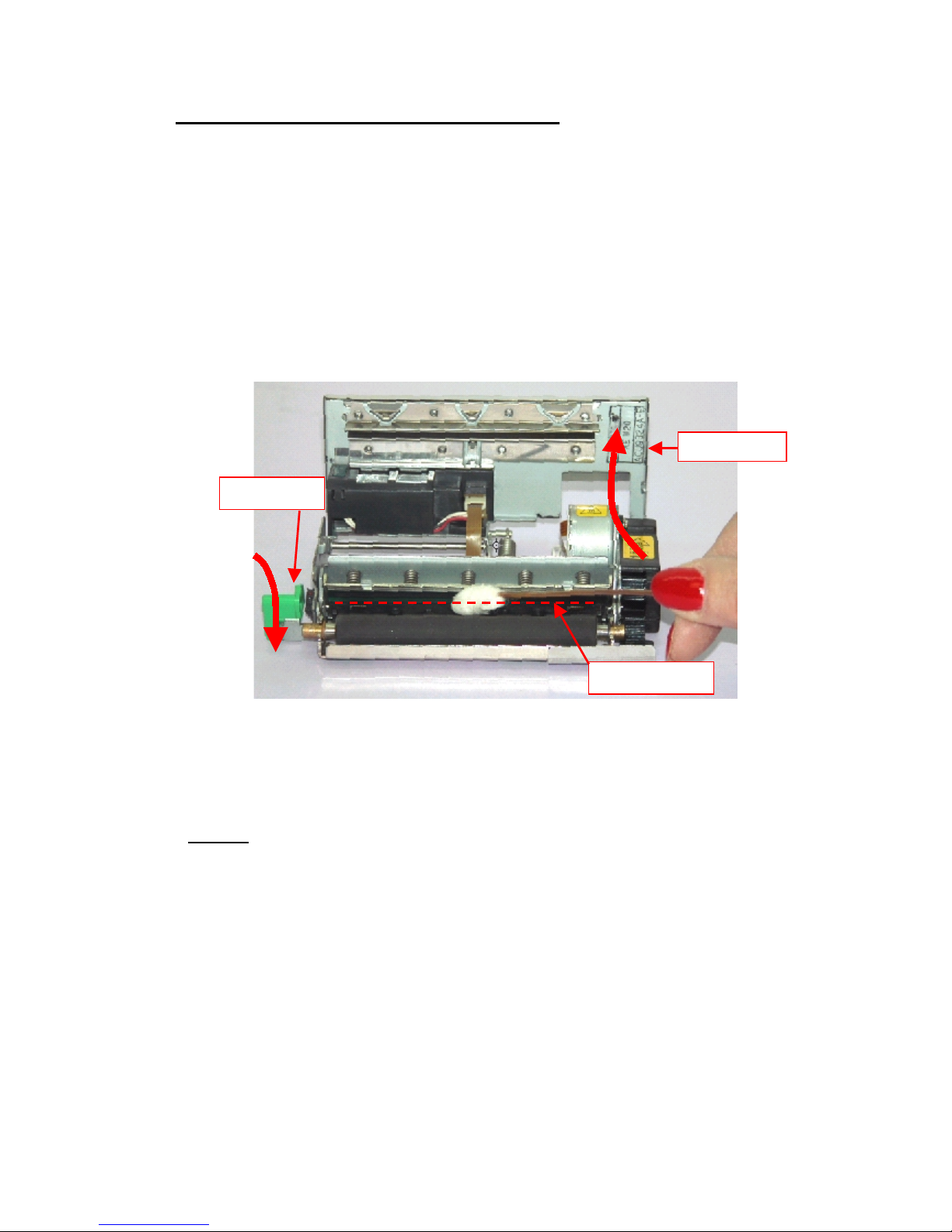
In order to clean the thermal print head, proceed as indicated by the following steps:
1)
Open up the paper cutter.
2)
Go down the head lever until clicking. The thermal head is held in the up
position .
3)
Soak a cotton sponge in alcohol (ethanol, methanol or IPA), and rub it gently
along the thermal head in order to remove the possible accumulation of
paper particles.
4)
Wait for alcohol to evaporate before inserting the paper roll and closing the
head.
Figure a. Head cleaning procedure
FENIX recommends cleaning the thermal print head periodically (every 2 or 3
months) in order to keep an optimal print quality.
NOTES
!
NEVER
touch the thermal elements of the print head with your hands.
!
NEVER
use metallic or piercing elements to clean the print head, as they
could scratch it.
!
The print head could be hot after printing. Make sure it has thoroughly
cooled down before proceeding to clean it.
!
Before connecting any communication data cable, check the printer is
working properly by executing the self-test.
Thermal Head
Paper cutter
Head lever

FENIX IMVICO
TK51/IF9000 OPERATION MANUAL
7/82
0 – INTRODUCTION
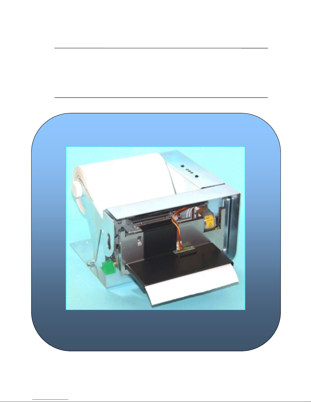
The TK51/IF9000 is a very high-performance embedded thermal line interface. Its
compact and functional design covers many professional uses. it is capable of printing
text, graphics, logo and bar code.
The TK51/IF9000 is intended to be integrated into the user’s final system. Its structure
allows an easy access both to the interface or the critical parts of the mechanism.
So, special care must be taken at choosing the TK51/IF9000 location, access and
protection from external damage. It can be used in laboratories, industrial and
professional environments.
The main features of the TK51/IF9000 are:
•
Simple installation and easy maintenanc e.
•
Low noise thermal printing.
•
Three paper widths available (60mm, 80 mm or 112 mm) depending on the SEIKO
LTP9000 series printing mechanism used.
•
High printing speed up to 250mm/s.
•
Line printing method: Printing is performed every time a text line is filled.
•
High reliability: 15 millio n lines.
•
Single 24V DC power supply.
•
No-paper, paper-near-end, head up and ticket pick up sensors.
•
High resolution printing (8 dots/mm).
•
IEEE 1284 parallel, serial RS232C or USB data input interface on-board.
•
Two internal character fonts (Font A = 12x24dots. Font B = 8x16dots).
•
Scalable font (independent scale in X / Y-axis), up to 64 times.
•
Bold, reverse, rotate and inverse character cap abilities.
•
Underline mode text, 1-dot or 2-dots thickness selectable.
•
Windows character font load capability.
•
Programmable character and line space.
•
Graphic bitmap printing capabilities.
•
Several format Bar Code: Code39, EAN13, ITF and Code128.
•
512 kbytes of buffer for data input.
•
Control code based on ESC / POS commands
(*)
.
•
Hexadecimal mode for easy software debugging.
•
Partial-cut or full cut selectable by software.
•
Logo load capability, thro ugh Windows driver.
•
Automatic paper load.
•
Self test, hexadecimal mode and configuration mode features.
•
Windows 95, 98, XP & 2000 drivers and showing program.
•
Linux driver.
•
Firmware update through the communication port
(**)
.
This manual is the printer operations’ guide and is intended for the designer’s
application. The following sections contain a detailed description of both the hardware
and the configuration software that allow obtaining the maximum benefit of the
TK51/IF9000.
(*)
ESC/POS are registered trademarks of Seiko Epson Corporation.
(**)
Contact with FENIX IMVCO or your distributor.

FENIX IMVICO
TK51/IF9000 OPERATION MANUAL
8/82
1 – GENERAL SPECIFICATIONS
1.1- PRINTING SPECIFICATIONS
a)
Printing method: Thermal line printing.
b)
Print Head:
Printing mechanism model type Number of dots
CAP9247 (60 mm paper-width model) 448 dots (= 56mm)
CAP9347 (80 mm paper-width model) 640 dots (= 80mm)
CAP9447 (112 mm paper-width model) 832 dots (= 104mm)
c)
Dot density: 203 dpi x 203 dpi (dpi: dots per inch (25.4mm)).
(8 dots/mm)
d)
Printing speed: up to 250 mm/s.
Automatic paper load: 100mm/s approx.
✔
Printing speed may be slower, depending on the
data transmission speed and combination of
control commands, environmental conditions,
or selection of the print density.
e)
Paper feeding: Feeding method "unidirectional with friction feed.
Feeding pitch "0,125mm (0,0049”)
Feeding speed "250 mm/s maximum
1.2- CHARACTER SPECIFICATIONS
a)
Character code tables: PC437 (USA, Europe Standard).
Others Windows
character tables can be loaded by FENIX application (See APENDIX G).
b)
Character structure: Font A: 12 x 24 dots (1,5 x 3 mm).
Font B: 8 x 16 dots (1 x 2 mm).
Font A is selected as the default.
FENIX IMVICO
TK51/IF9000 OPERATION MANUAL
9/82
1.3- ELECTRICAL CHARACTERISTICS
a)
Supply voltage: +24V DC ± 2.4V (± 10%)
b) Current consumption (at 24V):
Number of
simultaneously
activated dots
Maximum
640
Rated
29,4 A
26,7 A
Maximum
448
Rated
20,6 A
18,7 A
Maximum
256
Rated
11,8 A
10,7 A
Maximum
128
Rated
5,9 A
5,4 A
1.4- PAPER REQUIREMENTS
a)
Paper type: Single-ply thermal paper roll
b)
Specified thermal paper:
TF11KS-ET
TC11KS-LH
TL69KS-LH
TC98KS-LS
A different paper type may give a different print quality.
The paper thickness must be less than
155
µµµµ
m
.
c) Paper width:
CAP9247 mechanisms C AP9347 mechanisms CAP9447 mechanisms
60 mm /+0, -1
58 mm/+0, -1
82,55 mm/+0, -1
80 mm/+0, -1
112 mm/+0, -1
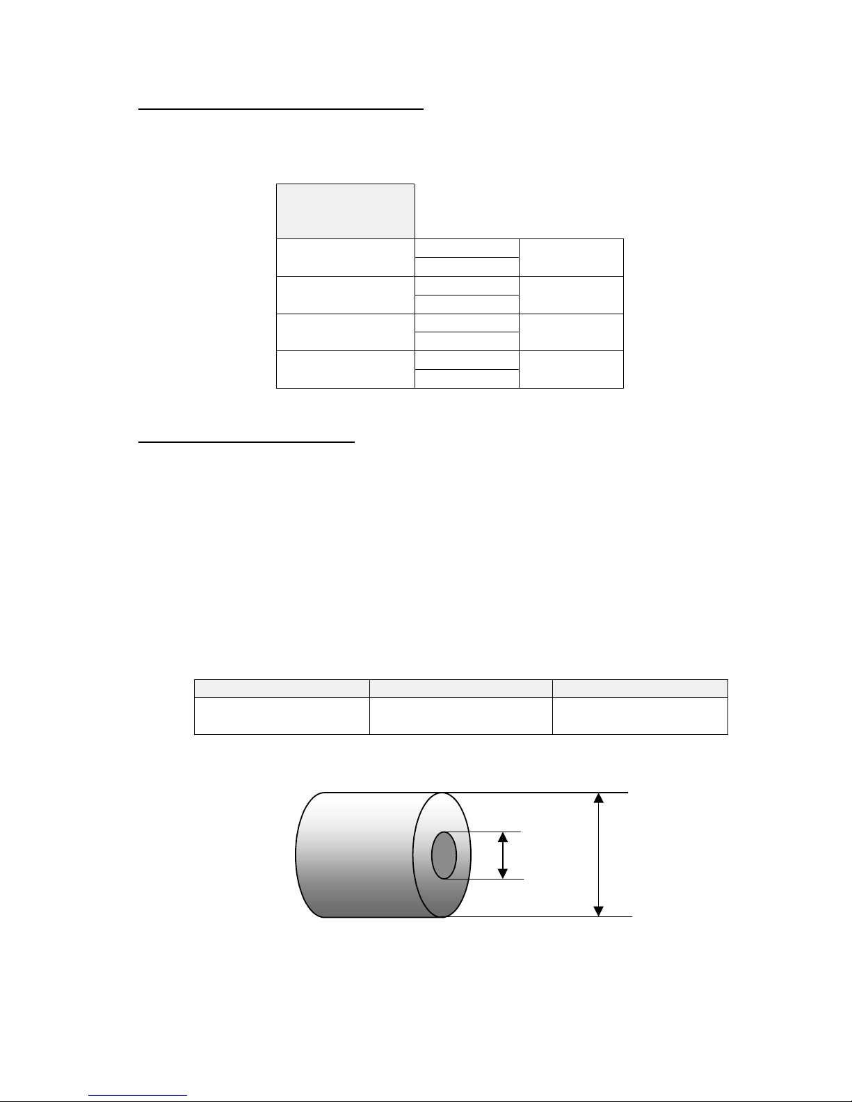
d) Paper roll:
25
mm
MINIMUM
150
mm
MAXIMUM
FENIX IMVICO
TK51/IF9000 OPERATION MANUAL
10/82
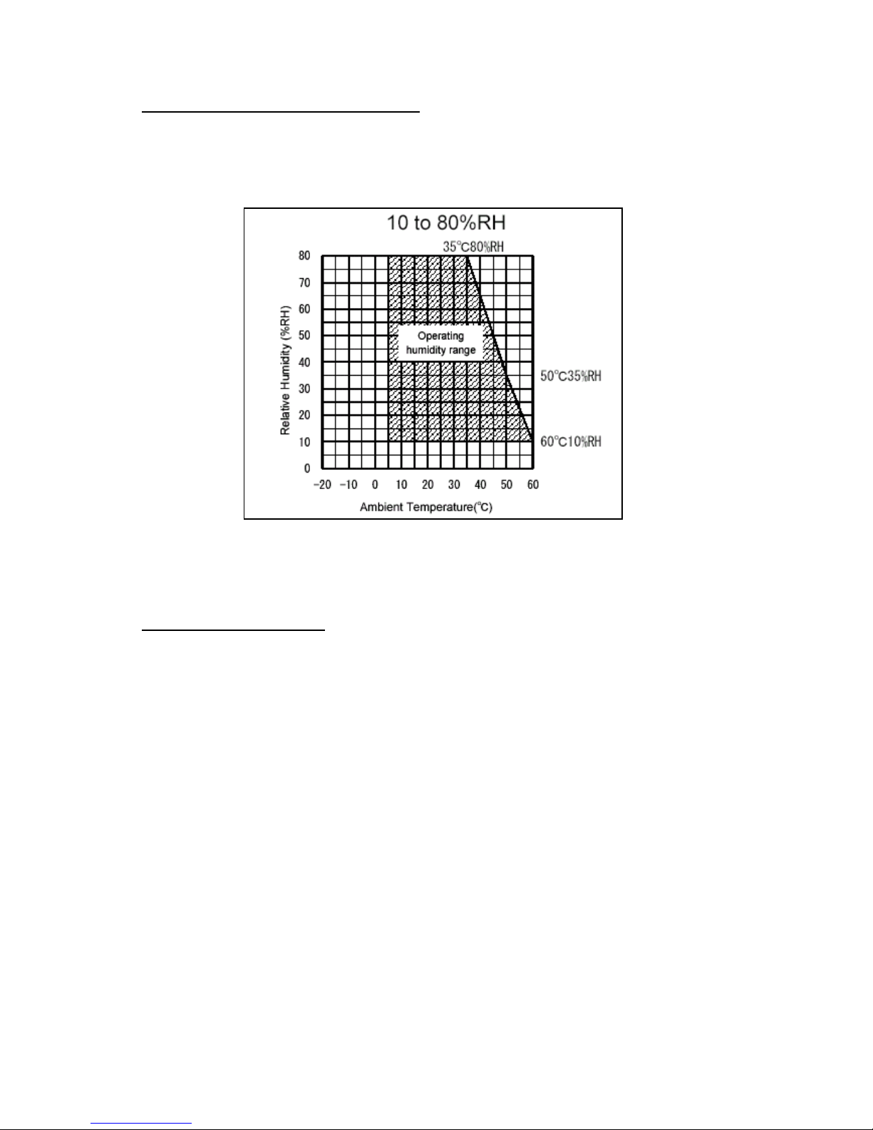
1.5- ENVIRONMENTAL CONDITIONS
a)
Operating Temperature: -20ºC to 80ºC
b)
Operating humidity: 10 to 80% (34ºC (93.2ºF) at 80%, non-condensing)
Fig. 1.1-
Operating Temperature and Humidity Range
1.6- INTERNAL BUFFER
The TK51/IF9000 printer has a
512 Kbytes
receiving buffer memory.
This big receiving buffer allows the printer working in the following way: Firstly, all data
is buffered, and afterwards the printing is performed at the maximum possible speed
without being affected by the communications time processing.

FENIX IMVICO
TK51/IF9000 OPERATION MANUAL
11/82
2 – INSTALLATION
2.1- TK51 INSTALLATION CONSIDERATIONS
There are some general con siderations to take into account when installing the
TK51printer.
A wrong installation might cause many issues like paper jam, difficult maintenance of
the printer, difficulty in changing the paper roll, etc. Moreover, a correct installation can
prevent the printer from being damaged by external agents, such as weather or
vandalism.
The TK51 is intended to be used in combination with the SEIKO CAP9000 series printer
mechanisms, and so, to result in a finished printer. This printer has been thought to be
installed in a bigger case or structure, or another kind of appropriate chassis.
The basic points that a correct installation must follow are:
•
Smooth exit of the ticket. Prevent problems with static electricity due to the nature of
the used materials. Be sure to make a good earth connection.
•
Avoid the final user’s access to the printer outlet.
•
Allow enough space and accessibility to reach the maintenance procedure points in
case it is needed. These points are:
✔
Printer Head and auto-cutter.
✔
Paper roll.
✔
Connectors.
✔
Leds and push-buttons.
Fig. 2.1-
Accessibility to reach the maintenance.
Connectors
Cutter
unblock
Print Head
Paper Roll
Leds and buttons
FENIX IMVICO
TK51/IF9000 OPERATION MANUAL
12/82
For these reasons, FENIX suggests the following systems as solutions to a correct
installation:
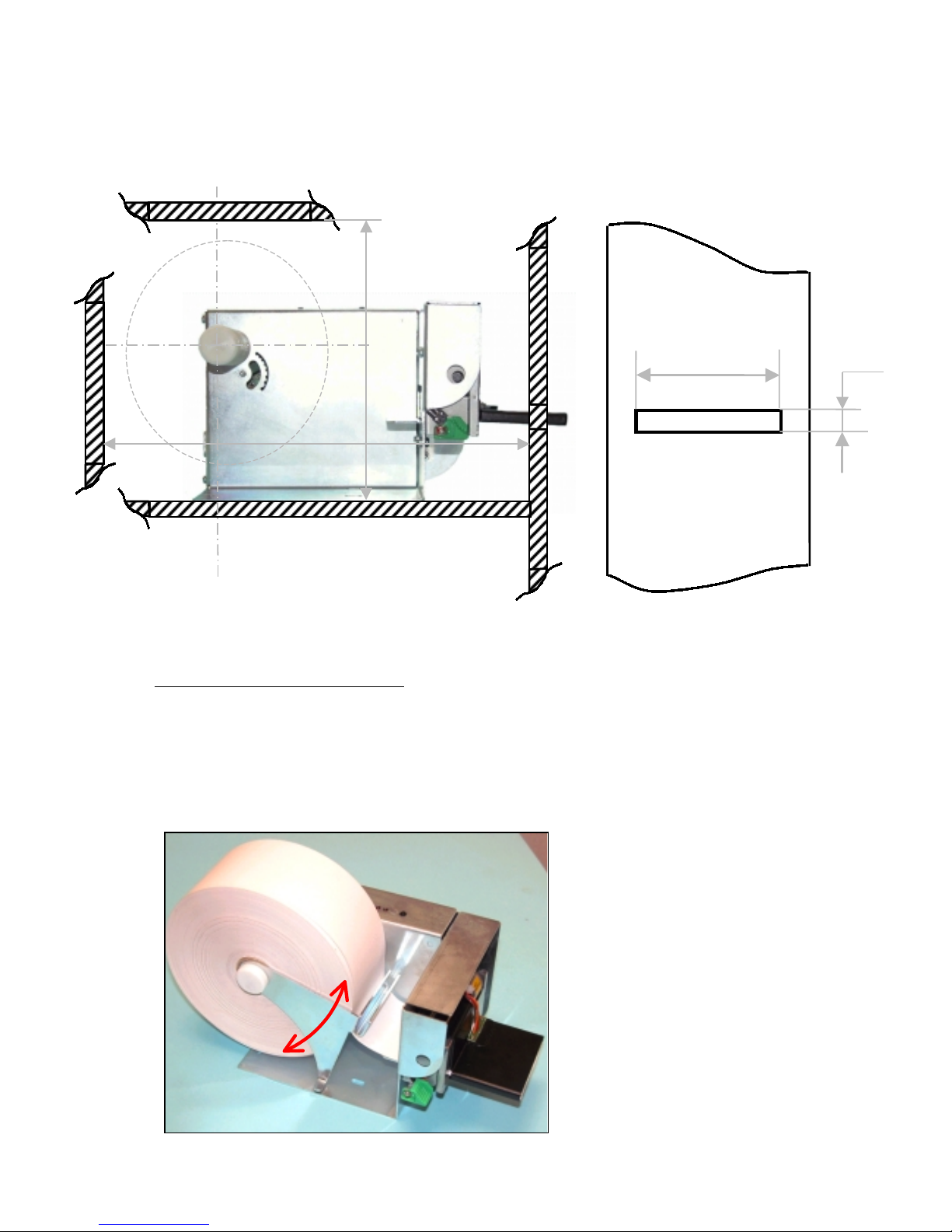
Fig. 2.2-
Installation considerations.
2.1.1- TK51 TENSION ROLLER
When big pap er rolls are being u sed, a damping sys tem to avoid any sudden change in
the paper strain (over 0,98N) is needful, since the step motor has the smallest driving
torque when it reaches the highest speed (250 mm/s). So, the backlash of paper
feeding system can be avoided.
The following picture shows the FENIX TK51 tension roller performed.
Fig. 2.3-
TK51 tension roller.
8mm
67 mm for TK51-60
87 mm for TK51-80
119 mm for TK51-112
175 mm minimum
approx.
250 mm minimum
approx.
FENIX IMVICO
TK51/IF9000 OPERATION MANUAL
13/82
2.2- TK51/IF9000 USER INTERFACE ELEMENTS
In the TK51/IF9000 user can find the following connectors:
•
CN1: Power supply connector.
•
CNx: Serial RS-232, parallel CENTRONICS or USB connector.
•
CN2: Mechanism connector.
•
CN9: Led and Buttons connector.
•
CN8: Paper-near-end connector.
•
CN9: Ticket pick-up connector.
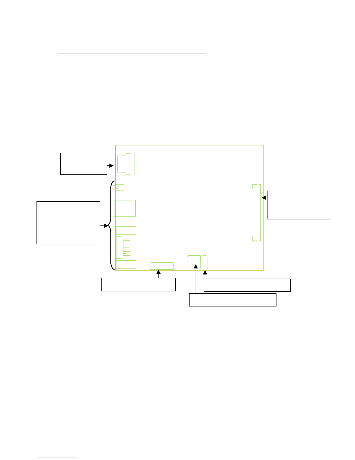
Fig. 2.4-
TK51/IF9000 connectors location.
CN1:
power supply
CN2:
LTP9000 serie
printer mechanisms
CN7: leds and buttons
Communication
interface:
"
Parallel Centronics,
"
RS-232 or
"
USB
CN8: paper-near-end sensor
CN9: Ticket pick-up sensor
FENIX IMVICO
TK51/IF9000 OPERATION MANUAL
14/82
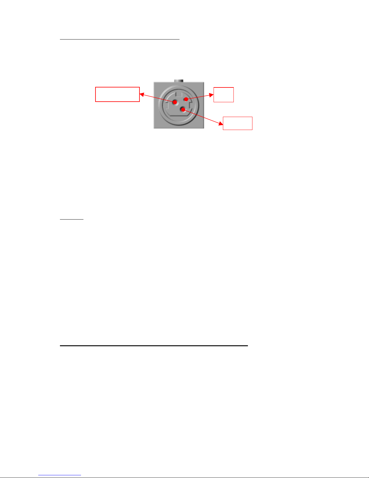
2.2.1- POWER SUPPLY CONNECTOR
Attach power supply cable to the 3-pin micro connector. Verify power supply voltage
before making the connection.
The connector is a female 3-pin HOSIDEN type, which have the following pin-out:
Fig. 2.5-
Power supply connector as seen from outside the TK51/IF9000.
""""
Use a 3-pin DC jack KPP-3P model or equivalent.
The TK51/IF9000 requires one power source: VCC (24V DC) for driving the thermal
head and motor. The power supply must meet the following conditions:
VCC:
24V DC +/- 2,4V (10%)
NOTES
✔
If the number of dots that are energized at the same time is increased, a higher
current will flow; therefore, the user should use a power supply with an adequate
current capability.
✔
When designing lines and bit images, take the printing ratio and print duty into
consideration.
✔
Print quality may be poor if the printing ratio or print duty is high.
Definitions:
•
Printing ratio: the number of printing dots (energizing pulses)/dot line.
•
Print duty: the number of printing dots (energizing pulses)/ elements/ paper
feed amount (two steps, including non-printing area)
WARNING: Beware not to invert the polarity of power supply. This may
irremediably damage the printer.
IMPORTANT NOTE ABOUT TK51/IF9000 POWER SUPPLY:
The current demand depends on the density of the printout. A 150W power
supply covers all adverse possibility (printing ratio of 100% black at any
temperature). However, if the average print ratio is not over 25%, a 60W power
supply can be used. Anyway, power supply must meet the peaks current that
mechanism requires, which are determined by the following formula:
Ipeak = [24 / 600] x number of printing dots
GN
D
24V DC
nc
FENIX IMVICO
TK51/IF9000 OPERATION MANUAL
15/82
A very important point to be aware of is the necessity of keeping the supply
wiring the shortest possible. When the printer is supplied with 24VDC, if the input
voltage drops a significant quantity the printer could stop working normally. The
longest (and thinnest) the wire the higher the impedance and therefore less
voltage will have in the input, especially during the high peak currents.
FENIX offers a 60W power supply as an accessory option (See APPENDIX F –
HOW TO ORDER).
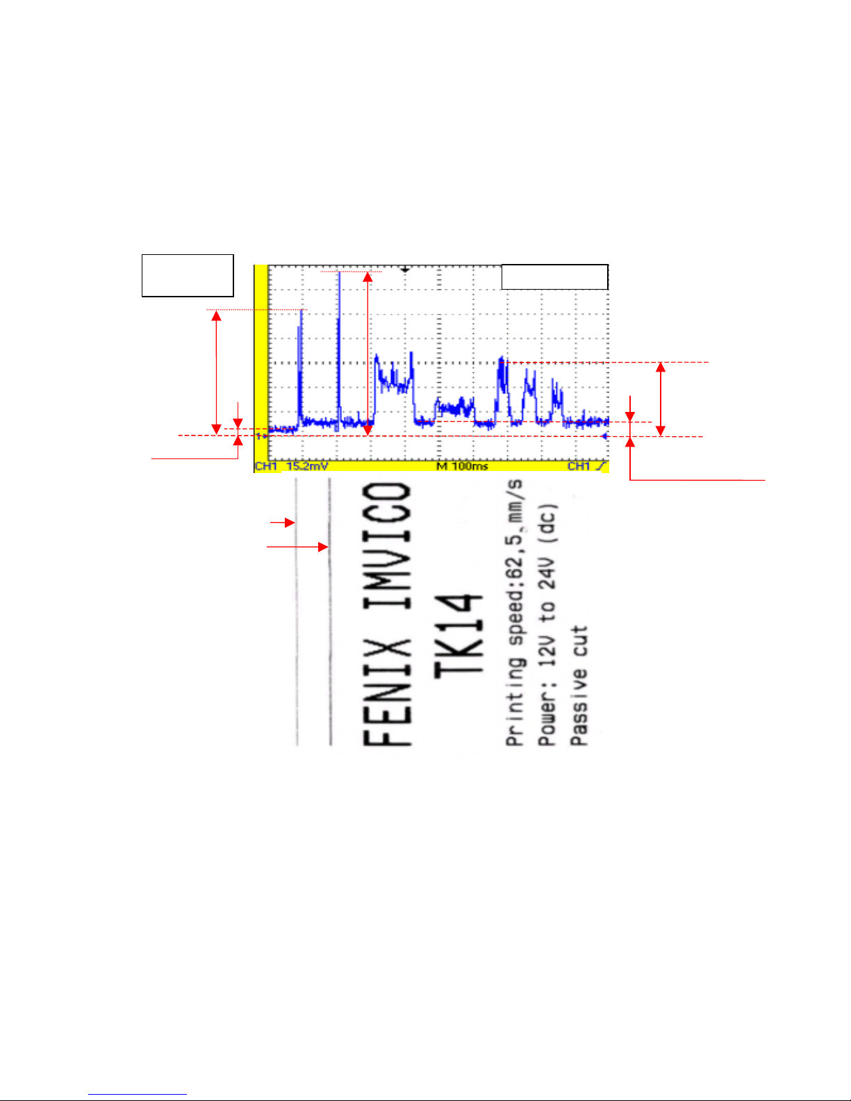
As an example, next figure shows the relationship between a sample ticket and
the input current measured.
Fig. 2.6-
Current
consumption
example.
I
(motor) = 0,5 A
(feed paper without printing)
I
standby
= 0,38A
R
shunt=0,02
Ω
=
1 dot line
2 dot lines
I
p
eak
= 3,9A
I
p
eak = 5,1A (5ms
)
I
peak= 2,2A ( 40ms)
FENIX IMVICO
TK51/IF9000 OPERATION MANUAL
16/82
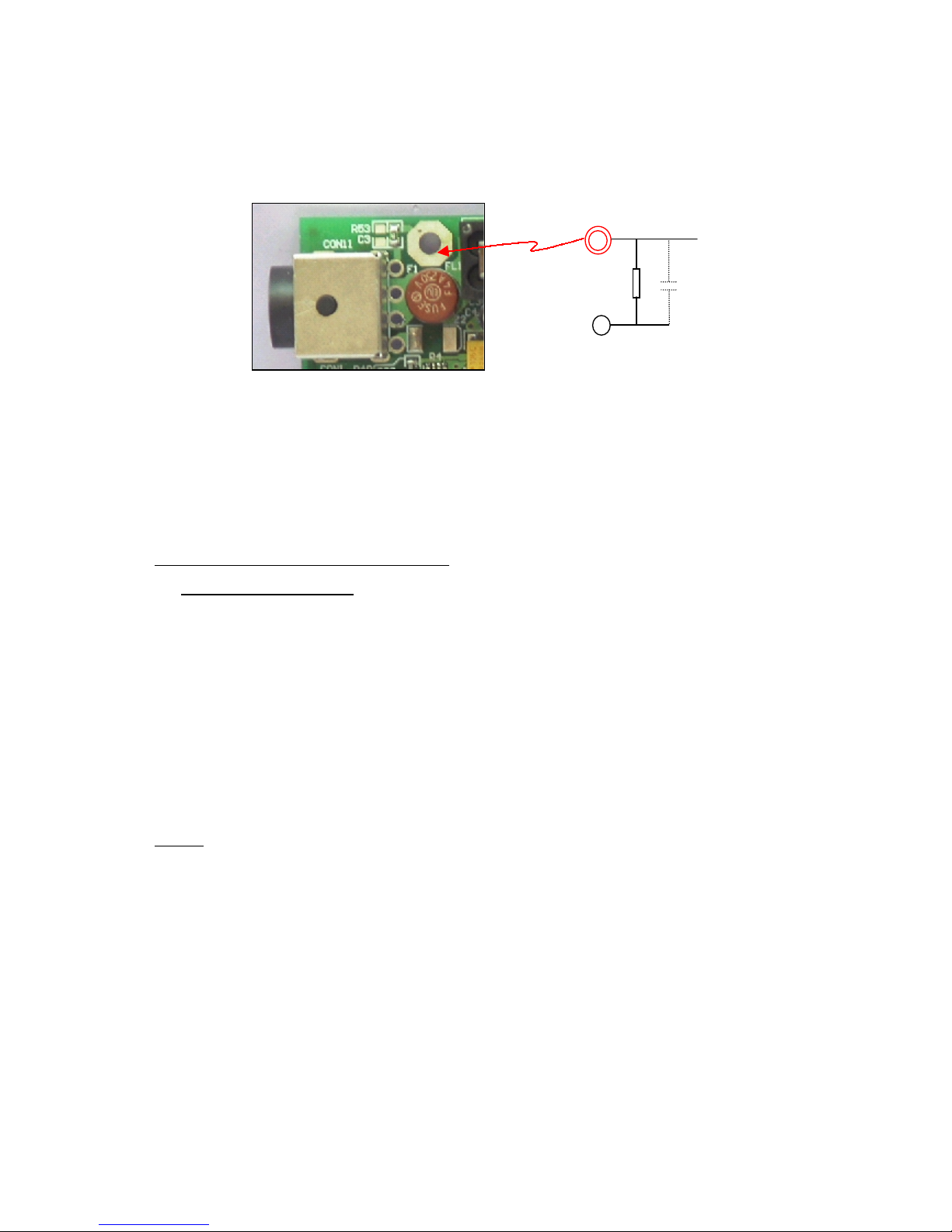
2.2.1.a) EARTH–GND connection.
The IF9000 arranges a terminal to connect the system EARTH to printer GND signal.
Between both terminals, there is a filter circuit implemented:
This RC filter avoids a current drift when the EARTH circuit is not good (there is not
EARTH connection or is defective, other noisy device in the system is injecting spurious
in the main power supply, etc).
If the installation system EARTH is very good (impedance<5 Ohm), it will be possible to
have a direct and optimum EARTH-GND connection, by shorting C3 pads (it is not
mounted by default).
2.2.2- SERIAL RS-232 CONNECTOR
2.2.2.1- Specifications
•
Data asynchronous serial transmission.
•
Handshaking: CTS/RTS control.
•
Signal levels (RS232): Logic “1” = - 3V to –15V.
Logic “0” = +3V to +15V.
•
Baud rate: 9600, 19200, 38400, 115200 bps (bits per second).
•
Data word length: 8 bits (fixed).
•
Parity Settings: None, even, odd.
•
Stop bits: Fixed to 1.
•
Connector (printer side): Male D-SUB9 pin connector.
NOTE The baud rate, and parity settings can be changed (refer to point
3.4.2-
PROGRAMMING MODE
).
EARTH
C3
R53
GND
1M
FENIX IMVICO
TK51/IF9000 OPERATION MANUAL
17/82
Pin Signal
name
Signal direction (from
the printer side)
Function
2 RXD Input
Data reception line.
3 TXD Output
Data transmission line.
4/DTR Output
This signal indicates whether an error occurs.
Logic “0” indicates that the printer is connected and ready to
receive data, and logic “1” indicates that the printer is offline.
The printer goes offline:
1) When the power is turned on until the printer becomes
ready for data transmission after it is initialized by a reset.
2) When the platen is open.
3) When the printer stops printing due to a paper-end.
4) When an error has occurred
5GND -
Signal ground.
6 /DSR Input
This signal indicates whether the host computer can receive
data.
7/RTS Output
This signal indicates whether the printer is busy. SPACE
indicates that the printer is ready to receive data, and MARK
indicates that the printer is busy.
8 /CTS Input
This signal indicates whether the host computer can receive
data.
(*) reception buffer is full when it increases till the maximum capacity (
512 Kbytes
).
Table 2.1-
Serial port pin-out.
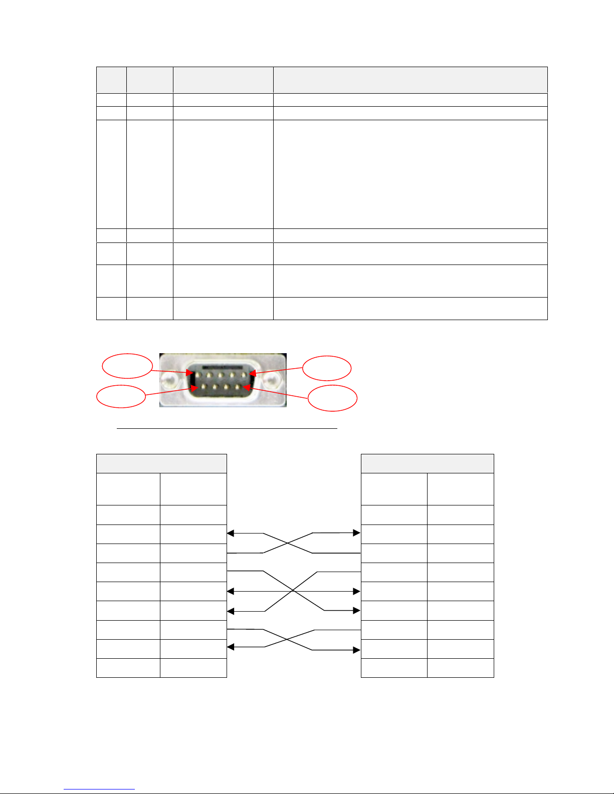
Fig. 2.7-
Serial interface connector
as seen from outside the
TK51/IF9000.
2.2.2.2- Serial interface connection example
The cable, which has the signal connection, as shown below must be used.
PRINTER SIDE
USER SIDE (PC)
D-SUB9
Pin Num.
Signal
Name
Signal
Name
D-SUB9
Pin Num.
1
(NC)
DCD
1
2
RxD
RxD
2
3
TxD
TxD
3
4
/DTR
/DTR
4
5
SG
SG
5
6
/DSR
/DSR
6
7
/RTS
/RTS
7
8
/CTS
/CTS
8
9
(NC)
RI
9
NC: Not Connected
Table 2.2
- Serial interface connection example.
Pin 9
Pin 5
Pin 6
Pin 1

FENIX IMVICO
TK51/IF9000 OPERATION MANUAL
18/82
The TK51/IF9000 serial input/output signals (RXD, /RTS and TXD) can be RS232C
level or TTL level (see
APPENDIX F- HOW TO ORDER
).
The TK51/if9000 receives and checks serial data according to the transmission baud
rate programmed.
If the input data is not printed correctly, the transmission conditions between the host
device and the TK51/IF9000 do not probably match. If this happens, the character
“?”
is continuously printed and user must adjust the transmission conditions so that they
match.
Serial data output (TXD): output pin, SUB-D9-3
•
Data is output according to the programmed transmission conditions.
Serial data input (RXD): input pin, SUB-D9-2
•
Data input port
•
Data is input from the host device according to the programmed transmission
conditions.
Serial busy (/RTS): output pin, SUB-D9-7
•
Indicates whether or not the printer is ready to receive data.
•
When the /RTS signal is “LOW”, data can be input.
Data terminal ready (/DTR): output pin, SUB-D9-4
•
Indicates whether the printer is ON_LINE/OFF_LINE.
•
When the / DTR signal is “LOW”, the printer is ON_LIN E
.
•
2.2.3- CENTRONICS PARALLEL CONNECTOR
The TK51/IF9000 performs the IEE1284 protocol (
NIBBLE MODE
).
Copyright © 1994 by the Institute of Electrical and Electronic Engineers, Inc.
2.2.3.1-Compatibility mode (Data transmission f rom host system to the p rinte r:
Centronics compatible)
*Any system sending data to the printer (PC, PLC, custom board, etc) is considered to
be a host system.
The compatibility mode supports compatibility with the Centronics parallel interface.
Specifications
Data transmission: 8-bit parallel
Synchronization: nSTB signal externally provided
Protocol: nACK (acknowledge) and BUSY signals
Signal levels: TTL compatible
Connector (user side): 36 pin MALE CENTRONICS (IEEE 1284 Type B).
FENIX IMVICO
TK51/IF9000 OPERATION MANUAL
19/82
•
Switching between online and offline mode
The printer does not provide any switch for online/offline mode. The printer is in offline
mode in the following cases:
a) When po we ring on or until the printer becomes ready for data transmission
b) After it is initialized by the reset signal from the interface
c) During the self-test.
d) When the platen is opened.
e) When the printer stops printing due to ‘out of paper’.
f) When a temporal voltage abnormality happens to the power supply
.
g) When an error occurs
.
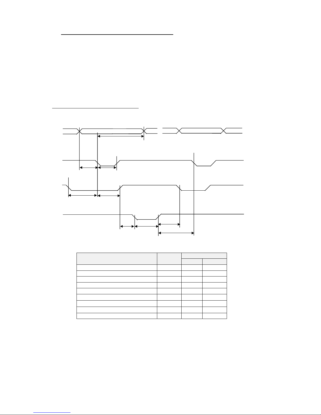
Timing diagram of data reception
Data n Data n+1
Data
tHold
nStrobe
tSetup tSTB
Busy Peripheral Busy
TReady tBUSY
nAck
tnBUSY
tReply tACK
tNext
Specification
Description Symbol
Min(ns) Max(ns)
Data hold time tHold 750 -Data setup time tSetup 750 -STROBE pulse width tSTB 750 -READY cycle idle time tReady 0 -BUSY output delay time tBUSY 0 500
Data processing time
tReply 0
∞
ACKNLG pulse width
tACK 500
10µs
BUSY release time
tnBUSY 0
∞
ACK cycle idle time tNext 0 --

FENIX IMVICO
TK51/IF9000 OPERATION MANUAL
20/82
Reverse mode (Data transmission from the printer to the host system)
The transmission of the printer status to the host system is implemented according to
the IEEE1284 standard (
NIBBLE MODE
).
2.2.3.2-Parallel interface pins assignment for each mode
Pin
Number
Source
Compatibility Mode
Nibble Mode
D-SUB25 PC
PIN Num.
1
Host
/Strobe
HostClk
1
2
Host/Ptr
Data0 (LSB)
Data0 (LSB)
2
3
Host/Ptr
Data1
Data1
3
4
Host/Ptr
Data2
Data2
4
5
Host/Ptr
Data3
Data3
5
6
Host/Ptr
Data4
Data4
6
7
Host/Ptr
Data5
Data5
7
8
Host/Ptr
Data6
Data6
8
9
Host/Ptr
Data7 (MSB)
Data7 (MSB)
9
10
Printer
/Ack
PrtClk
10
11
Printer
Busy
PrtBusy/Data3,7
11
12
Printer
PE
AckDataReq/Data2,6
12
13
Printer
Select
Xflag/Data1,5
13
14
Host
/Autofeed
HostBusy
14
15
Nc
Nd
16
GND
GND
18-25
17
FG
FG
18-25
18
Printer
Logic-H
Logic-H
19-30
GND
GND
18-25
31
Host
/Init
/Init
16
32
Printer
/Error
/DataAvail/Data0,4
15
33
GND
Nd
34
Printer
DK_status
Nd
35
Printer
+5v
Nd
36
Host
/SelectIn
1284-Active
17
Nc: Not connected Nd: Not defined
Table 2.3-
PC parallel connector (DB25).
FENIX IMVICO
TK51/IF9000 OPERATION MANUAL
21/82
NOTES
✔
The ‘n’ prefix used before a signal name means that they are active in ‘0’ logic level.
If the host system does not provide any of the signal lines mentioned above, both
communication types could fail.
✔
It is recommended to use twisted pair cables (signal/ground), with the return sides
connected to the system signal ground level.
✔
Do not ignore the nACK and BUSY signals during data transmissions. An attempt to
transmit data without nACK or BUSY control signals might cause lost data.
✔
The interface cables should have the minimum required possible length (
maximum
recommended length: 2 m
).
Fig. 2.8-
IEEE 1284-B connector from outsi de the TK51 /IF90 00
.
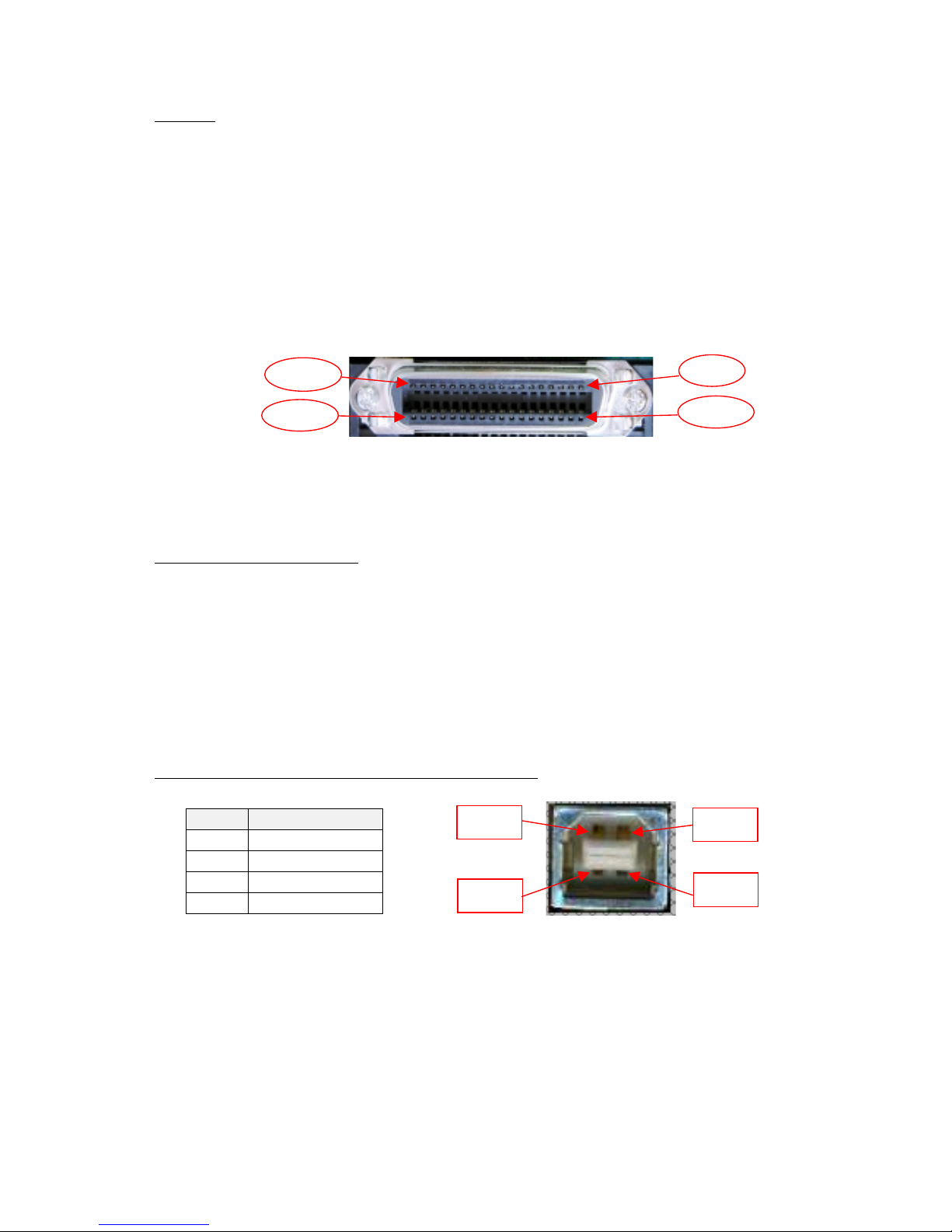
2.2.4- USB CONNECTOR
The TK51/IF9000 USB interface has the following general features:
•
USB specification USB 1.1 (12MHz full speed)
•
Transfer type Bulk
•
Maximum receive/transmit endpoint size 64 bytes
•
Current consumption from USB bus 2mA max.
2.2.4.1- Assignments of USB connector terminals
Pin Signal name
1 Vbus
2D –
3D+
4GND
Fig. 2.9-
USB connector as seen from outside the TK51/IF9000.
User has to use a standard “B” series USB connector.
Pin 18
Pin 36
Pin 19
Pin 1
Pin nº4
Pin nº1
Pin nº3
Pin nº2
FENIX IMVICO
TK51/IF9000 OPERATION MANUAL
22/82
2.2.5- THERMAL PRINTER CONNECTOR
TK51/IF9000 connects with the printer mechanism through
CON2
connector s:
Terminal
Number
Function
Terminal
Number
Function
1a –VPS1 Led anode (PE) 1b-PS1 Photo transistor collector (PE)
2a -VPS2 Led anode (OM) 2b-PS2 Photo transistor collector (OM)
3a -Vp Head drive power 3b-Vp Head drive power
4a -Vp Head drive power 4b-Datin Print data input
4a -CLK Print data transfer synchronize 5b-Latch Print data latch
6a -DST1 Head print activation signal 6b-DST2 Head print activation signal
7a -DST3 Head print activation signal 7b-DST4 Head print activation signal
8a -TH T hermistor 8b-GND GND
9a -GND GND 9b-GND GND
10a -GND GND 10b-GND GND
11a -GND GND 11b-GND GND
12a -Vdd Logic power supply 12b-DST5 Head print activation signal
13a -
DST6
Head print activation signal 13b-DST7 Head print activation signal
14a -Vp Head dri ve power 14b-Vp Head drive power
15a -Vp Head dri ve power 15b-Vp Head drive power
16a -A Paper feed motor driv e signal 16b-/A Paper feed mot or dri v e sig nal
17a -B Paper feed motor driv e signal 17b-/B Paper feed mot or dri v e sig nal
18a -HS Platen position sensor 18b-GND GND
19a -Cuta Cutter motor drive signal 19b-Cutb Cutter motor drive signal
20a -Cuts Cutter home position sensor 20b-GND GND
User side connector type: Housing: LY10-DC40 (JAE)
Contact: LY10-C1-1-10000 (JAE)
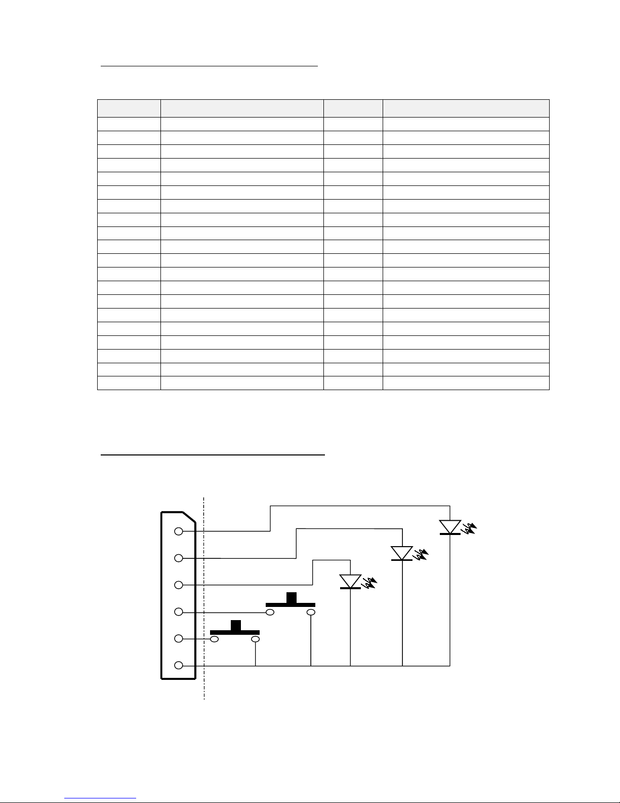
2.2.6- LEDS AND BUTTONS CONNECTOR
Leds and buttons on the TK51/IF9000 can be installed through connector CN7. Just
follow next connections (or see in APPENDIX F):
User side connector type: Housing: QH250-04H (Plastron)
Contact: QH250T-010 (Plastron)
Fig. 2.10-
Leds and buttons connections.
1
2
3
4
5
6
POWER
LED
PAPER
END LED
ERROR
LED
PAPER
FEED
PROGRAM
IF9000 side
User side
CON7

FENIX IMVICO
TK51/IF9000 OPERATION MANUAL
23/82
2.2.7- PAPER-NEAR-END AND TICKET PICK-UP CONNECTORS
.
Moreover than the no-paper sensor provided by the CAP9000 mechanism, the
TK51/IF9000 includes two connectors to control the outside paper status. In both of
them must be connected reflective optical sensors (see next table).
Through the paper-near-end sensor (CON8) user can control how much paper remain,
and therefore, to order a new paper reload before to fully exhaust the paper roll.
The ticket pick-up sensor (CON9) informs to the system if the last ticket printed has
been picked-up, so that it can take the suitable action. The status of these sensors can
be tested by the
DEL EOT
command. Next picture shows an example built in the TK51
printer (see in APPENDIX-F).
Fig. 2.11-
Paper-near-end and ticket pick-up connectors.
The optical sensor ratings must be in accordance with the following tables:
Item
Absolute Maximum ratings –25ºC
Symbol Rating
Forward current I
F
50 mA
Peak Forward current I
FM
1 A
Reverse voltage V
R
6 V
LED (input)
Allowable current P 75 mV
Collector-to-emitter voltage V
CEO
35 V
Emitter-to-collector voltage V
ECO
6 V
Collector current I
C
20 mA
Phototransistor
(output)
Collector loss P
C
75 mW
Total allowable loss Ptot 100 mW
Operating temperature Topr -25º to +85º C
Item
Input/output conditions
Symbol Conditions Std. Max.
Forward voltage V
F
IF = 20 mA 1,2V 1,4V
Peak forward voltage V
FMIFM
= 0,5A 3,0V 4,0V
Reverse current I
R
VR = 6V ----
10µA
LED (input)
Capacity between terminals Ct V
R
= 0V, f = 1kHz 50 pF 100pF
Phototransistor
(output)
Dark current I
CEO
VCE = 20V 10-9A10-7A
Photoelectric current I
C
IF = 4mA, VCE = 2V
45µA 120µA
Response time (at rise) tr
20µs 100µs
Response time (at fall) tf
I
C
= 100µA
V
CE
= 2V
R
L
= 1kΩ,
d = 1mm (1)
20µs 100µs
Transfer chara.
Leak current I
LEAKIF
= 4mA, VCE = 2V ----
0,1µA
(1) d = Sensing distance
User side connector type:
Housing: QH250-03H
Contact: QH250T-010
(Plastron)
CON9
1
3
2
CON8
IF9000
side
User side
FENIX IMVICO
TK51/IF9000 OPERATION MANUAL
24/82
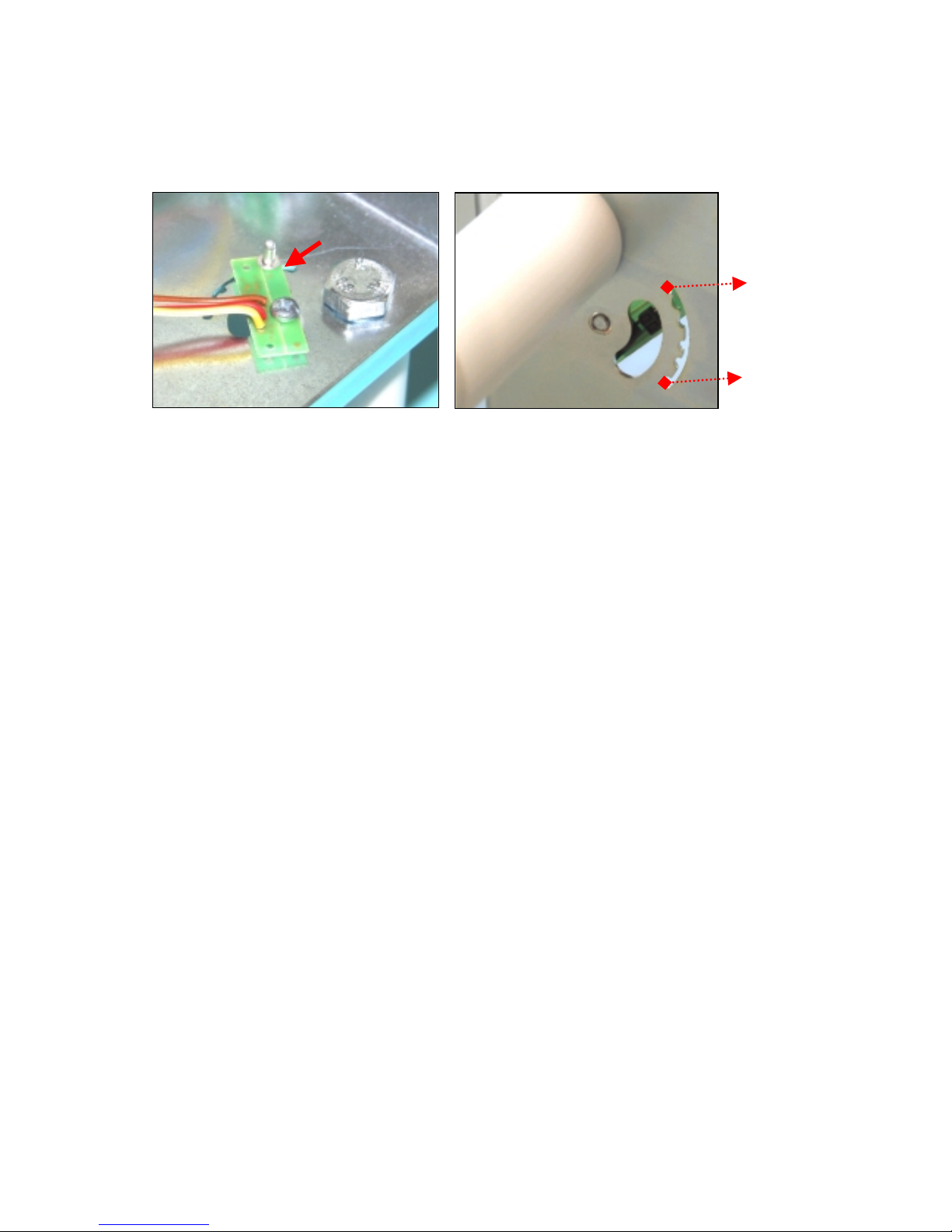
The user can adjust the near-end paper sensor position to determine what quantity of
paper (meters) wants to have from the detection. Next pictures show an approximate
reference of remainder paper, and how a nib (like a rivet) can help you to locate the
forto-sensor.
Fig. 2.12.- Near-end paper adjust.
10 meters approx.
2 meters approx.
FENIX IMVICO
TK51/IF9000 OPERATION MANUAL
25/82
3 – BASIC OPERATIONS
3.1- LOADING PAPER
When the printer runs out of paper, there are t wo wa ys of loading p aper: automatic and
manual.
Before starting the paper load sequence, please make sure the paper roll has been
placed in the right way.
Place the paper roll in the right direction. The thermal paper has only one surface
which can be printed (thermal side). In order to know which one it is, just scratch
the paper: the thermal side will show up the track on.
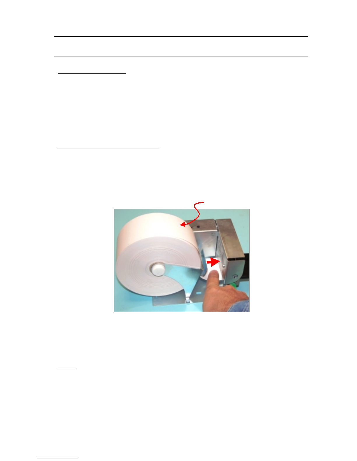
3.1.1- AUTOMATIC PAPER LOAD
1) Make sure the TK51 is power supplied.
2) Open the printing head and remove paper from inside the mechanism (if there is
any).
3) Make sure that the printing head is closed.
4) Make sure the paper end is cut in a straight way.
Fig.3.1-
Automatic paper load.
5) Put the paper end in the mechanism inlet.
6) Push the paper in until the TK51 detects it and starts the auto-load sequence.
7) Wait until the auto-load sequence extracts the paper from the printer outlet.
NOTE
✔ In the automatic paper load, the printer motor runs at low speed, because the
printer needs the maximum motor torque. Running at low speed, the motor is
noisier, but it is not a wrong performing.
Thermal side
 Loading...