

Fenix Imvico EPC1100 Operation Manual

EPC1100 THERMAL PRINTER
Operation Manual - Version 1.0
July-2000

FENIX IMVICO
EPC1100 OPERATION MANUAL
2/37
Revision list for the EPC1100 thermal printer operation manual.
Date: 11-07-2000
Page Type of revision Before change After change

FENIX IMVICO
EPC1100 OPERATION MANUAL
3/37
I N D E X
FIGURES AND TABLES 4
IMPORTANT NOTES ON EPC1100 HANDLING 5
1- INTRODUCTION 6
2- INSTALLATION 7
2.1- INSTALLING THE EPC1100 PRINTER 7
2.2- EPC1100 CONNECTORS 8
2.2.1- POWER SUPPLY CONNECTOR 8
2.2.2- COMMUNICATIONS CONNECTOR 10
2.2.2.1- SERIAL PORT CONNECTION (RS-232 / TTL) 10
2.2.2.2- PARALLEL PORT CONNECTION (CENTRONICS) 11
2.3- INTERFACING WITH A PERSONAL COMPUTER 12
2.3.1- Parallel input/output 12
2.3.2- Serial input/output 14
3- BASIC OPERATIONS 17
3.1- LOADING PAPER 17
3.2- TEST PRINT PROCEDURE 18
3.2.1- Programming the baud rate 18
3.2.2- Hexadecimal mode 19
4- ERROR PROCESSING 21
5- PRINTER COMMANDS 22
APPENDIX A- SOFTWARE EXAMPLES 33
APPENDIX B- SPECIFICATIONS 34
APPENDIX C- HOW TO ORDER 35
APPENDIX D- FAQ (Frequently Asked Questions) 36
APPENDIX E- PHYSICAL DIMENSIONS 37

FENIX IMVICO
EPC1100 OPERATION MANUAL
4/37
FIGURES AND TABLES
Fig. 2.1-
EPC1100 installation 7
Fig. 2.2-
EPC1100 connectors location 8
Fig. 2.3-
Power supply connector – CON1 9
Fig. 2.4-
Communications connector – CON4 10
Fig. 2.5-
Centronics cable pin-out 12
Fig. 2.6-
Timing for receiving parallel data 13
Fig. 2.7(A)-
RS-232 cable pin-out 14
Fig. 2.7(B)-
RS-232 cable pin-out 15
Fig. 2.8-
Serial input/output signal timing chart 15
Fig. 3.1-
Loading paper 17
Fig. 3.2-
Accessing the self-test button 18
Fig. 3.3-
Sample ticket 20
Fig. 5.1-
PC437 Standard Europe character table 22
Fig. 5.2-
Example of bitmap graphic 26
Fig. 5.3-
Bitmap image layout 27
Fig. 5.4-
Head logical blocks for dynamic division 30
Fig. 5.5-
Head logical blocks for fixed division 31
Table 2.1-
Serial connector pin-out 10
Table 2.2-
Parallel connector pin-out 11
Table 5.1-
Character/line in relation to character spacing 24
Table 5.2-
Printer command summary 32

FENIX IMVICO
EPC1100 OPERATION MANUAL
5/37
IMPORTANT NOTES ON EPC1100 HANDLING
In order to guarantee a long life of the printer, it is necessary to keep some
precautions on the EPC1100 handling. Please read carefully next lines to make a
good use of the printer.
SAFETY PRECAUTIONS
•
BEWARE not to invert power supply polarity. This may irremediably
damage the printer.
•
Use power supply voltage within specified range. Overvoltage may
irremediably damage the printer. Voltage under the specified range may
cause incorrect operations. FENIX advises to use, at least, a 30W power
supply (for VCC=VP= 5v dc and fixed division mode) .
•
When switching the power supply ON, turn on Vcc and Vp simultaneously,
or turn on Vcc f irst, an d then Vp.
•
When switching the power supply OFF, turn off Vcc and Vp simultaneously,
or turn off Vp first , and then Vcc.
•
When using two power supply lines (a Vcc=5v line and a Vp=4,2~8,5v
line), both GND should be common.
•
Keep EPC1100 away from water or any other liquid.
•
DO NOT put any objects into the printer. It could cause severe damage like
shortcircuits, broken thermal head or general printer failure.
•
DO NOT blow the EPC1100.
•
NEVER modify the EPC1100.
•
DO NOT try to repair the EPC1100 by yourself. If some failure is detected
contact with your usual dealer technical service.
RECOMMENDATIONS
•
Before connecting any input interface, verify the correct operation of the
EPC1100 printer with self test feature.
•
Avoid using EPC1100 in environments where there are excessive
temper atures or moistu re.
•
Place the EPC1100 in such a way that connection wires are not crushed or
twisted.

FENIX IMVICO
EPC1100 OPERATION MANUAL
6/37
____________________________________________________________________
1 – INTRODUCTION
The EPC1100 is a low cost, high performance thermal printer which covers any
application where small place is available, and low noise and low power supply are
needed. It has graphics capabilities and bar code representation.
The structure of the EPC1100 allows setting it into a panel as well as into other
appropriate chassis where a printer is needed. It can be used in industrial,
professional o r l aboratory environments.
Its easy manipulation makes it suitable for applications where the handling of the
printer does not need specific technical knowledge, such as receipts, security
systems, medical instrumentation, process control systems, etc.
Main features of the EPC1100 printer are:
•
Easy maintenance structure.
•
Easy installation procedure.
•
Compact and lightweight.
•
Single 5V dc power supply.
•
High resolution printing (8 dots/mm).
•
Both parallel CENTRONICS and serial (RS-232 and TTL) data input interface.
•
Allows normal, double width, double height and double width-height attributes.
•
Scalable font (independent scale in X / Y axis).
•
Programmable character and line space.
•
Graphic bitmap printing capabilities.
•
CODE39 Bar Code.
•
Hexadecimal mode for easy software debugging.
•
Easy paper loading with paper roll drop – in.
•
Self test feature.
•
PC 437 Standard Europe character table used.
This manual is a guide of the printer operations and is addressed to the application’s
designer. In following chapters ther e is a detailed description of hardware and
software configuration to take advantage of the features of the EPC1100 printer.
FENIX IMVICO
EPC1100 OPERATION MANUAL
7/37
2 - INSTALLATION
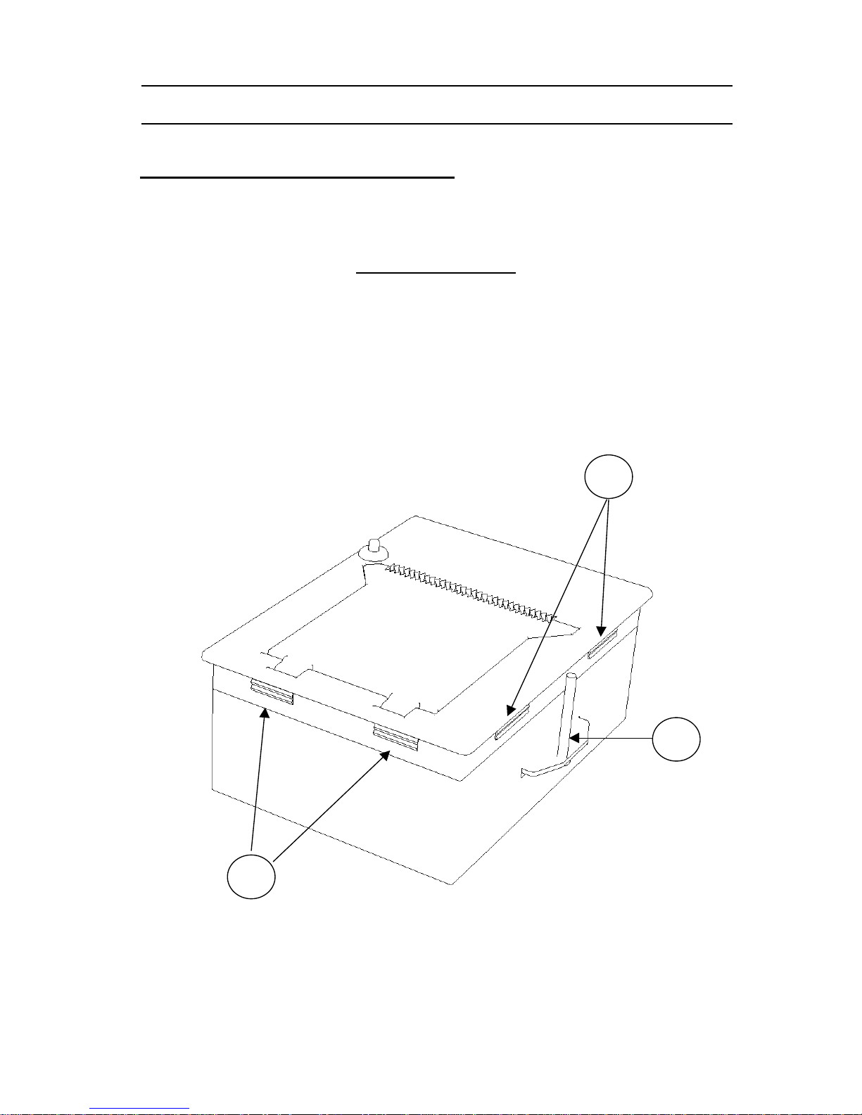
2.1.- INSTALLING THE EPC1100 PRINTER
The EPC1100 is a panel printer thought to be easily set into a wall, a case or another
kind of appropriate receptacle. To install the EPC1100 printer follow next steps:
•
Make a rectangular hole of
91x124 mm (approx.)
on the surface where the printer
will be set.
•
Place the EPC1100 printer into the hole and push until the pieces marked with an
A
in
Fig. 2.1
make pressure enough to secure the EPC1100 to the surface.
•
Optionally, two metric screws DIN965 M3 / L35 (Part B in
Fig. 2.1
) can provide
better holding of the EPC1100 to the surface.
•
Connect the power supply and the communications port to the back side of the
printer (see
Fig.2.2
EPC1100 connectors location
or refer to chapters
2.2.1.-
Power
supply connector
and
2.2.2.-
Communications Connector
).
Fig. 2.1-
EPC1100 installation.
A
A
B
FENIX IMVICO
EPC1100 OPERATION MANUAL
8/37
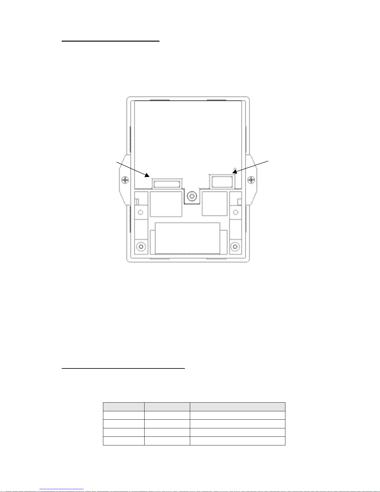
2.2.- EPC1100 CONNECTORS
On the back side of the EPC1100 user can find the two necessary connectors:
•
CON1: Power supply connector.
•
CON4: Communications connector.
Fig. 2.2-
EPC1100 connectors location.
2.2.1- POWER SUPPLY CONNECTOR
Attach power supply cable to connector
CON1
. Verify power supply voltage before
making the connection.
Terminal nº Signal Name Function
1 GND GND
2 VP Printer power (4,2v~8,5v dc)
3 VCC Logic power (5v dc)
4 GND GND
CON1:
Power supply
CON4:
Communications

FENIX IMVICO
EPC1100 OPERATION MANUAL
9/37
Fig.2.3-
Power supply connector CON1.
Use a connector JST Ref. VHR-4N (housing)
SVH-21T-P1.1 (contacts)
The EPC1100 requires two power sources: VP (4,2v~8,5v dc) for driving the thermal
head and motor, and VCC (5v dc) for logic electronics. The power supplies must
satisfy the following conditions:
VCC (for logic electronics) :
5v dc +/- 0,25v , 0,2 A
VP (for thermal head and motor):
4,2v ~ 8,5v dc
The maximum current consumption (Ipmax) for thermal head and motor change
according to the following equation :
Ip = N*Vp/(Rh) +0,4 (A)
Ip: Peak current (A)
N: Number of dots that are driven at the same time (
See 5- PRINTER COMMANDS
)
N = 64 (dynamic division)
N = 192 (fixed division)
Vp: Head driven voltage (V)
Rh: Head resistance (Ohms)
0,4 : maximum current for driving the motor
•
For example, if VP = VCC = 5v dc, N =64 and Rh = Rank A (~ 187 ohms)
Ipmax = 64*5/(178)+0,4 = 2,19 A
•
If VP=VCC = 5v dc, N=192 and Rh = Rank A (~ 187 ohms)
Ip
max = 192*5/(178)+0,4 = 5,79 A
See HOW TO ORDER if using a different VP=5v dc.
WARNING : Beware not to invert the polarity of power supply. This may
irremediably damage the printer. Power must be turned on in proper
order. Turn on both Vcc and Vp simultaneously, or turn on Vcc first and then Vp.
Otherwise, the EPC1100 thermal printer may be damaged. To turn the power off,
first turn off Vp and then Vcc or turn off both Vcc and Vp simultaneously.
FENIX advises to use, at least, a 30w power supply (for VCC=VP=5V dc) when
fixed division print mode is used.
4 3 2 1
FENIX IMVICO
EPC1100 OPERATION MANUAL
10/37
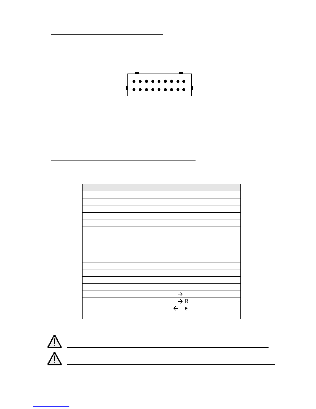
2.2.2.- COMMUNICATIONS CONNECTOR
Both SERIAL RS-232/TTL and PARALLEL CENTRONICS ports use the same
connector –
CON4
.
Fig. 2.4
- Communications connector CON4.
Use a connector JST Ref.- PHDR-18VS (housing)
SPHD-001T-P0.5 (contacts)
2.2.2.1.- SERIAL PORT CONNECTION (RS-232 / TTL)
If you use the serial interface, attach serial port cable to connector
CON4
.
Terminal nº Signal Name
Function
1
2
3
4
5
6
7
8
9
10
11
12
13
14
15
TXD
Out Transmit Data
16
/RTS
Out Rquest to Send
17
RXD
In Receive Data
18
GND
Table 2.1-
Serial connector pin-out.
See HOW TO ORDER to select the RS232 or TTL voltage level.
See chapter “3.2.1.- Programming the baud rate” to configure
Serial Po rt.
1
18

FENIX IMVICO
EPC1100 OPERATION MANUAL
11/37
2.2.2.2- PARALLEL PORT CONNECTION (CENTRONICS)
If you use the parallel interface, attach CENTRONICS cable to connector
CON4
.
Terminal nº Signal Name Function
1/STBIn
Strobe
2 DATA0
3 DATA1
4 DATA2
5 DATA3
6 DATA4
7 DATA5
8 DATA6
9 DATA7
In Data Bus
10 /ACK OutAcknowledge
11 BUSY OutBusy
12 PE OutPaper Error
13 /ERROR OutError
14 GND GND
15
16
17
18
Table 2.2-
Parallel connector pin-out.
FENIX IMVICO
EPC1100 OPERATION MANUAL
12/37
2.3- INTERFACING WITH A PERSONAL COMPUTER
Before connecting any cable to EPC1100 check the correct pinout.
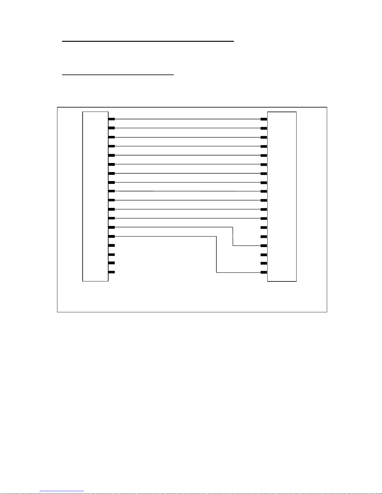
2.3.1- PARALLEL INPUT/OUTPU
Following drawings show how to make the interface cables with a compatible PC.
Fig. 2.5
- Centronics cable pinout.
The busy and acknowledge signals are output every byte. If 128 bytes have been
stored in the EPC1100 input buffer, the busy status continues until the amount of data
stored in the input buffer becomes 127 bytes or less.
1
2
3
4
5
6
7
8
9
10
11
12
13
14
15
16
17
18
1
2
3
4
5
6
7
8
9
10
11
12
13
14
15
16
17
18 to 25
/Strobe
Data 0
Data 1
Data 2
Data 3
Data 4
Data 5
Data 6
Data 7
/Acknowledge
Busy
Paper end
/Error
GND
EPC1100 CENTRONICS
CONNECTOR
PC CENTRONICS DB-25M
CONNECTOR
 Loading...