

Fenger FDM-4000i Installation & Configuration Manual
INSTALLATION & CONFIGURATION MANUAL
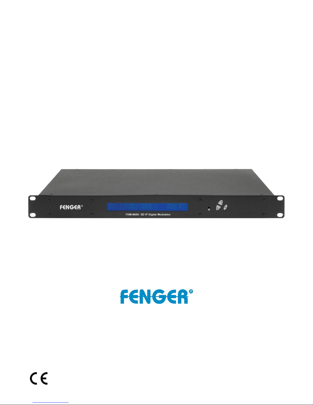
FDM-4000i
4-port SD Digital Modulator with IP
FDM-4000i Manual V1.0

TABLE OF CONTENTS
SAFETY PRECAUTIONS ..................................................................................................................... 3
PACKAGE CONTENTS ........................................................................................................................ 4
PRODUCT DESCRIPTION ................................................................................................................... 4
SPECIFICATIONS ................................................................................................................................. 5
INSTALLATION .................................................................................................................................... 6
UNPACKING and INSPECTION ...................................................................................................... 6
PRODUCT PICTURES and DIAGRAMS......................................................................................... 6
HARDWARE INSTALLATION and CONNECTIONS .................................................................... 7
DEVICE Programming and Setup .......................................................................................................... 8
Connecting to the GUI Interface: ............................................................................................................ 8
Encoder Programming and Setup via GUI Interface: ............................................................................. 9
Overview Page of Fenger Encoder ..................................................................................................... 9
Common Setup ................................................................................................................................. 10
RF Setup ........................................................................................................................................... 11
Encoder Setup ................................................................................................................................... 12
IP Streaming Setup ........................................................................................................................... 13
Network Configuration ..................................................................................................................... 14
Administration .................................................................................................................................. 15
Front Panel LCD Encoder Menu Map .................................................................................................. 17
Modulator Configuration via Front Panel LCD .................................................................................... 18
Common Setup Menu ....................................................................................................................... 19
RF Setup Menu ................................................................................................................................ 19
Encoder Setup Menu ....................................................................................................................... 20
Web Management Network Setup .................................................................................................... 23
DIGITAL MODULATOR NOTES ....................................................................................................... 24
- 2 -
FDM-4000i Manual V1.0

SAFETY PRECAUTIONS
The presence of this symbol is to alert the installer and user to the
presence of uninsulated dangerous voltages within the product’s
enclosure that may be of sufficient magnitude to produce a risk of
electric shock.
TO REDUCE THE RISK OF FIRE OR ELECTRIC SHOCK, DO NOT EXPOSE THIS
DEVICE TO RAIN OR MOISTURE. DO NOT OPEN THE UNIT. REFER SERVICING
TO QUALIFIED PERSONNEL ONLY.
DO NOT apply power to the unit until all connections have been made, all components
have been installed and all wiring has been properly terminated.
DO NOT terminate, change or uninstall any wiring without first disconnecting the unit’s
power adapter from the device.
DO NOT connect the power supply to the device if the power cord is damaged.
DO NOT cut the power cord.
DO NOT plug the power cord into an AC outlet until all cables and connections to the
device have been properly connected.
The device should be installed in an environment consistent with its operating temperature
specifications. Placement next to heating devices and ducts is to be avoided as doing so
may cause damage. The device should not be placed in areas of high humidity.
DO NOT cover any of the device’s ventilation openings.
DO NOT cover or obstruct the device’s fan or fan openings.
If the device has been in a cold environment allow it to warm to room temperature for at
least 2 hours before connecting to an AC outlet.
- 3 -
FDM-4000i Manual V1.0

PACKAGE CONTENTS
This package contains:
One FDM-4000i SD IP Digital Modulator
One Power Cord
One Installation Manual
Inspect the package before starting installation to ensure there is no damage and all supplied
contents are present. Contact your distributor or dealer should the device be damaged or
package contents are incomplete.
PRODUCT DESCRIPTION
FENGER’s FDM-4000i encoder/modulator converts Digital Video Broadcasting (DVB)
standard definition video and audio signals to DVB-T. The unit features programmable channel
and network names. Adjustable RF output (Normal, Inverted, and C.W.), adjustable logic
channel numbering (LCN) and adjustable attenuation are standard features. The unit’s frontmounted LCD display and controls allow for easy configuration and adjustments.
The FDM-4000i SD IP Digital Modulator is perfect for multi-video distribution solutions in the
commercial and institutional market (hotels, motels, sports bars, boats, restaurants, hospitals,
casinos, business and university campus, etc.).
- 4 -
FDM-4000i Manual V1.0
SPECIFICATIONS
FDM-4000i
4-input SD Encoder Modulator with IP
Input
Video Input
CVBS
Video Input Level
0.7 - 1.4V (peak-to-peak)
Video Mode
PAL / NTSC
Audio Input
Stereo
Audio Input Level
0.4 - 4.8V (peak-to-peak)
Video & Audio Connectors
RCA female
Impedance
75 Ohm
RF Output
Standard
DVB-T according to EN 300 744
Frequency Range
E2 (50.5MHz) ~ S20 (296.5MHz) with 7 MHz interval
S21 (306MHz) ~ E69 (858MHz) with 8 MHz interval
Channel Bandwidth
7 MHz, 8 MHz
MER
36dB typical
Output Level
105dBμV typical
Output Level Adjustment
0 to -20dB (1dB step)
Output Impedance
75 Ohm
Output Connector
"F" female
IP Output
Streaming Method
RTP/UDP Unicast, RTP/UDP Multicast
Output Connector
RJ-45, 1Gbps
Modulation
Video Resolution
PAL 720x576@25ftp / NTSC 720x480@30ftp
Video Compression
MPEG-2, MP@HL 4:2:0
Audio Compression
MPEG-1 Layer II
LCN Processing
Yes
Carrier (OFDM Mode)
2K, 8K
Guard Intervals
1/32
Code Rate (FEC)
7/8
Constellations
64 QAM
Programming Interface
Local Setup
LCD Display + keypad
Remote Management
via Web Browser from any PC
Language
English
General
Power Supply
100 to 240 VAC, 50/60 Hz
Power Consumption
2.050 mA
Temperature Rating
0 ºC to +45 ºC
Dimensions
482.7mm x 240mm x 44.4mm, 1RU
Weight
3.40 Kilograms
*Specifications are subject to change without prior notice
- 5 -
FDM-4000i Manual V1.0
INSTALLATION
System Installer must adhere to Article 820-40 of the NEC that provides
guidelines for proper grounding and specifies that the cable ground shall
be connected to the grounding system of the building, as close to the
point of cable entry as possible.
UNPACKING and INSPECTION
Each unit is shipped factory tested. Ensure all items are removed from the container prior to
discarding any packing material.
Thoroughly inspect the unit for shipping damage with particular attention to connectors and
controls. If there is any sign of damage to the unit or damaged or loose connectors contact
your distributor immediately. Do not put the equipment into service if there is any indication of
defect or damage.
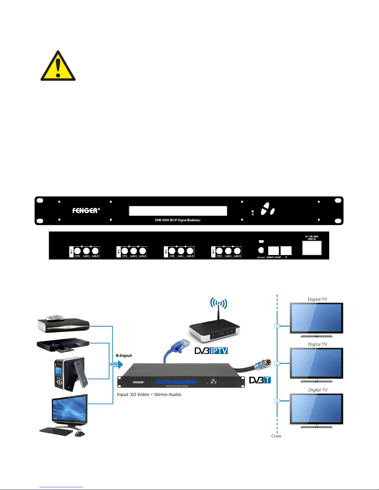
PRODUCT PICTURES and DIAGRAMS
- 6 -
FDM-4000i Manual V1.0

HARDWARE INSTALLATION and CONNECTIONS
1. The unit is designed to be rack mounted in a standard EIA 19” rack.
2. Use a 75Ω coaxial cable with RCA connectors to connect the video source (e.g., STB,
DVD, VCR, and Camera) to the unit’s yellow RCA VIDEO INPUT jack (IN1…IN4).
Repeat this step for each video source connection.
It is highly recommended that quality coaxial cable and connectors be used for all
video source connections.
3. Use RCA cables to connect the audio source to the red / white AUDIO L and AUDIO R
INPUT jacks (IN1…IN4). Use the red and white jacks for audio input or either one for a
single input.
Repeat this step for each audio source connection.
Be sure the video and audio connections for each source are consistent with the unit’s
inputs (IN1…IN4).
It is highly recommended that quality cables and connectors be used for all audio
source connections.
4. Use a quality 75Ω coaxial cable with “F” connectors from the unit’s RF OUT jack to the
distribution system (combiner or reverse splitter).
5. Connect the included power cord to the unit’s POWER plug.
6. Connect the power cord to an appropriately rated AC power outlet.
- 7 -
FDM-4000i Manual V1.0

DEVICE Programming and Setup
To setup and program the Encoder you can use the GUI interface or the LCD Front Panel
Connecting to the GUI Interface:
Connect an Ethernet cable directly (no Cross Over cable required) to the Web Management
Port on the rear panel of the Encoder or connect the Ethernet cable to an Ethernet switch.
Connect an Ethernet Cable to your PC.
Static IP address
A static IP address must be used on the computer you use to configure the Encoder.
Refer to the computer’s operating software documentation for assistance on using static
IP addresses.
Starting GUI Interface
Open a web browser window
Enter “http://192.168.1.9” in the web address field
Note: To setup the encoder using the Front Panel LCD see “Modulator Configuration via Front
Panel LCD”.
- 8 -
FDM-4000i Manual V1.0
 Loading...