

Page 1

Operator's Manual
VarioGuide
VarioGuide Novatel
VarioGuide Trimble
Marktoberdorf
AGCO GmbH - Johann-Georg-Fendt-Str. 4 - D-87616
Marktoberdorf
FENDT is a worldwide brand of AGCO
© AGCO 2015
Original Operator's Manual
November 2015
438.020.070.012
4832
EAME
English
Page 2

Page 3

Dear Customer
Please note the following:
• Before using the tractor, carefully read through this operator’s manual and familiarize yourself with all
operating controls and their functions before you begin work. This also applies to the operator's manual
for implements.
•
Observe all the operating and maintenance instructions. If you do so, your tractor will give you many
years of economic and trouble-free operation. You will find an overview of all maintenance operations in
the maintenance schedule in this maintenance manual.
• Maintenance and repair work should only be carried out at your service workshop.
Disregarding the symbols and the associated safety instructions—which are divided into three hazard
levels—can lead to considerable damage to the tractor, the mounted implements or other property.
Adhering to the safety instructions is also required in order to prevent such damage from occurring.
.
VarioGuide
438.020.070.012
Page 4

.
VarioGuide
438.020.070.012
Page 5

Proper use of VarioGuide
This tractor is designed exclusively for normal agricultural operations or suchlike, e.g. municipal
applications. Any other type of use is considered unauthorized. The manufacturer will not be liable for any
damage resulting from such use, which will be entirely at the owner's risk.
Authorized use also includes observing the operating, maintenance and repair conditions set out by the
manufacturer in order to protect your claims under warranty if necessary.
Special attention must be paid to safety instructions marked with this symbol, as well as the words
DANGER, WARNING and CAUTION.
Operation, maintenance and repair of the tractor are restricted to persons who are familiar with this
equipment and aware of the inherent dangers.
The relevant accident prevention regulations must be observed, as must as any generally acknowledged
safety, industrial medicine and traffic regulations. The manufacturer does not accept liability for damage
resulting from unauthorized modifications to the machine.
Since it is working equipment, the tractor is not suitable for taking on board or transporting children and
young persons. If children or young persons are nonetheless present in the tractor, the operator must be
aware that they require strict supervision. It must be impossible for any children and young persons on
board to operate the technical controls on the tractor or any equipment mounted on it. Under no
circumstances may children or young persons remain alone in the cab when the operator leaves the
tractor.
.
Disclaimer
AGCO-Fendt accepts no responsibility or liability for damage to property, injury to persons or death caused
by improper or negligent use of its products, including the VarioGuide system and its components. AGCO
moreover accepts no responsibility for the use of AGCO implements or of the GNSS signal for purposes
other than those intended.
AGCO is also unable to guarantee the accuracy, integrity, continuity or availability of the GNSS signal.
When operating the VarioGuide system, it is the operator's responsibility to exercise general caution and
navigation-related judgment.
The following pages contain specific safety precautions that must be read before using VarioGuide
products and observed during their use.
NOTE:
When third-party way line guidance systems are used with Fendt equipment, AGCO Fendt shall exclude
any warranty or liability for damage to property, injury to persons or death.
Copyright law
The information contained herein is protected by copyright by AGCO. In the case of the names of
companies and products specified here, these may be registered brand names or trademarks of the
relevant owner.
The duplication of this document, or parts thereof, in any form and in any way is forbidden without express
written agreement from AGCO. No part of this document may be quoted by persons who are not
employed by AGCO without written approval from AGCO. AGCO reserves the right to make changes to
the information contained in this document without prior notice.
Although this document has been prepared with the utmost care, AGCO shall not be held liable for any
mistakes or omissions. No liability shall be accepted for damages in connection with the use of this
information.
VarioGuide
438.020.070.012
Page 6

.
Up-to-date at the time of going to press
The high safety and quality level of the FENDT machines is ensured by constant development work on
designs, equipment and accessories. We would therefore ask you to bear in mind that changes in form,
equipment or technology may be required at any time. The details of delivery, appearance, technical data
and functions of the machine is only correct at the time of going to press It may not be possible to deliver
some of the equipment until later, or it may only be offered in certain markets. No claims may be derived
from the information, illustrations or descriptions contained in this instruction sheet.
VarioGuide
438.020.070.012
Page 7

Table of contents
VarioGuide
1 Introduction ..............................................................11
1.1 Delivery of VarioGuide system ......................................13
1.2 OPERATOR'S MANUAL FENDT VarioGuide ...........................14
2 Safety instructions ........................................................15
2.1 Safety and accident prevention regulations ..........................17
2.1.1 Marking of places that affect your safety ................................17
2.1.2 Advice for the operator .............................................17
2.1.3 Safe operating environment .........................................18
2.1.4 Switching off in an emergency situation ................................18
3 VarioGuide definitions and specifications ...................................19
3.1 Definitions .........................................................21
3.1.1 GNSS and correction signal ..........................................21
3.1.2 Satellite reception ................................................21
3.1.3 Signal interruption ................................................23
3.1.4 Static and dynamic accuracy (satellite drift) ..............................23
3.1.5 Convergence time ................................................23
3.1.6 Conditions of use and application possibilities ............................23
3.1.7 Restrictions .....................................................23
3.1.8 Switch-off limits .................................................24
3.2 Specification .......................................................25
3.2.1 Topcon accuracy specifications .......................................25
3.2.2 Trimble accuracy specifications .......................................25
4 Quick Start ...............................................................27
4.1 VarioGuide menu tree ..............................................29
4.2 VarioGuide info ....................................................31
4.3 Vario-Guide Main Menu .............................................32
4.4 Implement selection ................................................34
4.5 Field Settings ......................................................36
4.6 Steering behavior ..................................................38
4.7 Signal settings .....................................................39
4.8 System info .......................................................40
5 Map view .................................................................41
5.1 Overview ..........................................................43
5.1.1 Map view menu tree ..............................................43
5.1.2 Map view ......................................................43
5.2 Display ............................................................45
5.2.1 Full screen .....................................................45
5.2.2 Zoom .........................................................46
5.2.3 Info bar ........................................................46
5.2.4 Steering status ..................................................47
5.2.5 Novatel bar indicator, Trimble ........................................47
5.3 Functions ..........................................................49
5.3.1 Set markers .....................................................49
5.3.2 Marker settings ..................................................50
5.3.3 Worked area settings ..............................................50
VarioGuide
438.020.070.012
Page 8

Table of contents
6 VarioGuide components and calibrations ...................................53
6.1 Calibrations ........................................................55
6.1.1 Calibrate steering angle sensor and steering valve .........................55
7 Start-up ..................................................................63
7.1 Load implement ....................................................65
7.1.1 Caution ........................................................65
7.1.2 Load implement settings (7" terminal) ..................................65
7.1.3 Load implement settings (10.4" terminal) ................................66
7.2 Create implement ..................................................67
7.2.1 Call up implement settings on 7" .....................................67
7.2.2 Call up implement settings on 10.4" ...................................68
7.2.3 Front-mounted implement ..........................................69
7.2.3.1 Install front-mounted implement ...............................69
7.2.3.2 Determine the working width, navigation point distance and coupling
length ........................................................70
7.2.3.3 Set the working width of the front-mounted implement ..............71
7.2.3.4 Set the navigation point of the front-mounted implement .............72
7.2.3.5 Set the coupling length for the front-mounted implement ............73
7.2.3.6 Set the center of the front-mounted implement ....................74
7.2.3.7 Set the trigger for the front-mounted implement ...................75
7.2.4 Rear-mounted implement ...........................................76
7.2.4.1 Install rear-mounted implement ................................76
7.2.4.2 Determine the working width, navigation point distance and coupling
length ........................................................77
7.2.4.3 Set the navigation point of the rear-mounted implement ..............78
7.2.4.4 Set the coupling length for the rear-mounted implement .............79
7.2.4.5 Set the center of the rear-mounted implement ....................80
7.2.4.6 Set the trigger for the rear-mounted implement ....................81
7.3 Save mounted implement data ......................................82
7.3.1 Save implement on stopping ........................................82
7.4 Exchange implement data and field data .............................84
7.4.1 Plug in the USB stick and call up data exchange ...........................84
7.4.1.1 Insert USB stick ...........................................84
7.4.1.2 Call up data exchange on 10.4" ................................84
7.4.2 Transfer implement data and field data to the USB stick .....................85
7.4.2.1 Select and transfer all data ....................................86
7.4.3 Transfer implement and field data from the USB stick to the terminal ...........87
7.4.3.1 Select and transfer all data ....................................89
7.5 Correction signals ..................................................90
7.5.1 Overview of correction signals depending on the receiver ...................90
7.6 Submeter range with NovAtel receiver ...............................91
7.6.1 Autonomous ....................................................91
7.6.2 EGNOS / WAAS .................................................92
7.7 Centimeter range with NovAtel receiver .............................93
7.7.1 FENDT base station ...............................................93
7.7.1.1 Configure the FENDT base station correction signal .................93
7.7.1.2 Fallback: FENDT base station ..................................94
7.7.2 External station ..................................................95
7.7.2.1 Configure the external station correction signal .....................95
7.7.2.2 External fallback station ......................................96
7.7.3 RTK network (internal mobile radio modem) ..............................96
7.7.3.1 Configure the internal mobile modem correction signal ...............96
7.7.3.2 Activate/deactivate internal mobile modem fallback ..................98
7.7.4 RTK network (external mobile radio modem) .............................98
VarioGuide
438.020.070.012
Page 9

Table of contents
7.7.4.1 Configure the external mobile modem correction signal ...............98
7.8 Submeter range with Trimble receiver .............................. 100
7.8.1 Autonomous ................................................... 100
7.8.2 EGNOS / WAAS .................................................101
7.8.3 RangePoint RTX .................................................102
7.9 Decimeter range with Trimble receiver ..............................103
7.9.1 CenterPoint RTX Satellite .......................................... 103
7.9.1.1 Set correction signal for Centerpoint RTX Satellite ..................103
7.9.1.2 Fallback for Centerpoint RTX Satellite ...........................104
7.10 Centimeter range with Trimble receiver ............................105
7.10.1 FENDT base station ............................................. 105
7.10.1.1 Configure the FENDT base station correction signal — Trimble AG-715
450 MHz radio modem ........................................... 105
7.10.1.2 Configure the FENDT base station correction signal (Trimble 900 MHz) .
7.10.2 RTK network (internal GSM/GPRS modem) ............................ 107
7.10.2.1 Configure the internal mobile modem correction signal (GSM/GPRS) ... 107
7.10.3 RTK network (external mobile radio modem) ........................... 108
7.10.3.1 Configure the external mobile modem correction signal .............108
7.10.4 Trimble receiver settings ..........................................109
7.10.4.1 xFill settings ............................................ 109
106
7.11 Field Settings .................................................... 111
7.11.1 Add field ..................................................... 111
7.11.2 Record field boundary ............................................112
7.11.3 Record/manage obstacles .........................................115
7.12 Way-line .........................................................119
7.12.1 Create and save way line .........................................119
7.12.2 Path to path distance ............................................ 124
7.13 Check system .................................................... 125
7.13.1 Check system info/system status ...................................125
7.14 Activate VarioGuide system .......................................127
7.14.1 Switch on automatic way line guidance ...............................127
7.15 Adjust way line ...................................................128
7.15.1 Way line offset ................................................ 128
7.16 Headland settings ................................................ 129
7.16.1 Headland settings .............................................. 129
7.16.2 Headland management TI/AutoTI ................................... 131
7.17 Operation with the base station ................................... 133
7.17.1 Brief description ............................................... 133
7.17.2 Scope of delivery and accessories ...................................133
7.17.3 LED and keys on the base station ................................... 136
7.17.4 Initial start-up ..................................................137
7.17.5 Operating modes ............................................... 138
7.17.6 Start-up ...................................................... 138
7.17.7 Set the base station channel on the tractor ............................ 139
7.17.8 Operate base station with external battery .............................141
8 Faults and remedy ........................................................143
8.1 Fault diagnostics .................................................. 145
8.1.1 Problems and possible remedial action ................................ 145
9 Appendix ................................................................ 149
9.1 Glossary .......................................................... 151
9.1.1 Glossary ...................................................... 151
VarioGuide
438.020.070.012
Page 10

Table of contents
VarioGuide
438.020.070.012
Page 11

Table of contents
1. Introduction
1.1 Delivery of VarioGuide system ...........................................13
1.2 OPERATOR'S MANUAL FENDT VarioGuide ................................14
VarioGuide 11
438.020.070.012
Page 12

Table of contents
12 VarioGuide
438.020.070.012
Page 13

1.1 Delivery of VarioGuide system
Vehicle type
1. Introduction
Chassis no.
OmniSTAR
Serial number
Information to be provided at vehicle delivery
Draw attention to safety instructions in the vehicle operator's manual, on the vehicle itself and in the
VarioGuide operator's manual.
Draw attention to country-specific compliance with regulations for the registration and use of radio
signals.
System delivery and instructions on the VarioGuide track guidance system.
For further information and notes, refer to the appropriate sections in the operator's manual.
Read safety precautions
Select correction signal
Implement settings in VarioGuide
Configure trigger settings in VarioDoc
Check system status
Create way-line
. . . / . . / . . . . .
OSN
Service workshop
Switch on automatic way line guidance
Delivered on . . . . . . . . . . . . . . . .
Signature of mechanic . . . . . . . . . . . . . . . . .
Customer's signature. . . . . . . . . . . . . . . . .
VarioGuide 13
438.020.070.012
Page 14

1. Introduction
1.2 OPERATOR'S MANUAL FENDT VarioGuide
Fendt VarioGuide
This operator's manual is only valid in conjunction with the operator's manual for the tractor
AGCO GmbH
Maschinen und Schlepperfabrik 87616 Marktoberdorf / Bavaria / Germany
www.fendt.com
© PSD / AP 2015-11
4832
14 VarioGuide
438.020.070.012
Page 15

Table of contents
2. Safety instructions
2.1 Safety and accident prevention regulations ...............................17
2.1.1 Marking of places that affect your safety .....................................17
2.1.2 Advice for the operator ..................................................17
2.1.3 Safe operating environment ..............................................18
2.1.4 Switching off in an emergency situation .....................................18
VarioGuide 15
438.020.070.012
Page 16

Table of contents
16 VarioGuide
438.020.070.012
Page 17

2. Safety instructions
2.1 Safety and accident prevention regulations
2.1.1 Marking of places that affect your safety
Make sure that any other users have read all the safety instructions as well.
The various levels of safety instructions can be distinguished as follows:
DANGER:
This symbol, together with the word DANGER, means there is an immediate risk of
danger that must be prevented to avoid the risk of DEATH OR SEVERE INJURY.
WARNING:
This symbol, together with the word WARNING, means a potential risk of danger that
must be prevented to avoid the risk of DEATH OR SEVERE INJURY.
CAUTION:
This symbol, together with the word CAUTION, means there is a potential danger that
must be prevented to avoid the risk of MINOR INJURY.
The operator's manual is an integral part of the vehicle package and must be passed on to any subsequent
owner in the event of resale. The attention of the new owner should be drawn to this information.
If this manual is lost or damaged and you need a new one, please contact your Fendt dealer, from whom
you will be able to purchase a replacement.
2.1.2 Advice for the operator
The purpose of VarioGuide is to assist the operator in steering the tractor. The operator must remain
attentive at all times and have full control over the machine.
VarioGuide cannot detect obstacles such as persons or objects that are not defined and saved in the
system. While automatic steering is in operation, the operator must ensure that a suitable distance is kept
from such obstacles.
VarioGuide may be deactivated briefly if the GNSS or correction signal is lost. It is therefore essential that
the operator is constantly aware of the position of the tractor and the conditions in the field.
WARNING:
Hazard due to vehicle movements Risk of injury and death! Material damage is possible.
When driving on public roads or in areas where there is a risk of injury to others, the
electrohydraulic steering system must not be pre-activated; automatic way-line guidance
must not be activated.
WARNING:
Hazard due to vehicle movements Risk of injury and death! Material damage is possible.
While the system is switched on, the operator must remain on the operator platform
within the vehicle at all times. The operator must attentively follow all the operating
conditions and be ready to intervene at any time, should this be necessary.
WARNING:
Hazard due to vehicle movements Risk of injury and death! Material damage is possible.
Before the operator leaves the tractor, the automatic steering system must be switched
off and the tractor must be parked properly.
VarioGuide 17
438.020.070.012
Page 18

2. Safety instructions
2.1.3 Safe operating environment
WARNING:
Hazard due to vehicle movements Risk of injury and death! Material damage is possible.
The automatic way line guidance system may only be used if the tractor is located in an
open area away from persons, buildings and other machinery: At a safe distance from
persons. At a safe distance from obstacles.
lines. On private property without public access.
WARNING:
Hazard from operating the system outside of approved national signal areas Risk of injury
and death! Material damage is possible. Do not operate VarioGuide and its base station
outside the authorised national frequency ranges, to avoid interference with other
systems (remote-controlled cranes, forestry cranes, etc.).
At a safe distance from high-voltage power
2.1.4 Switching off in an emergency situation
The operator can switch off the way line guidance system in an emergency situation by moving the
steering wheel, giving him manual control over the vehicle. To switch the way line guidance system back
on, the switch-on conditions must be fulfilled and the activation button must be pressed.
WARNING:
Hazard due to vehicle movements Risk of injury and death! Material damage is possible.
While the system is switched on, the operator must remain on the operator platform
within the vehicle at all times. The operator must observe all operating conditions
attentively and be ready to intervene immediately whenever necessary.
18 VarioGuide
438.020.070.012
Page 19

Table of contents
3. VarioGuide definitions and specifications
3.1 Definitions ..............................................................21
3.1.1 GNSS and correction signal ...............................................21
3.1.2 Satellite reception .....................................................21
3.1.3 Signal interruption .....................................................23
3.1.4 Static and dynamic accuracy (satellite drift) ...................................23
3.1.5 Convergence time .....................................................23
3.1.6 Conditions of use and application possibilities .................................23
3.1.7 Restrictions ..........................................................23
3.1.8 Switch-off limits ......................................................24
3.2 Specification ............................................................25
3.2.1 Topcon accuracy specifications ............................................25
3.2.2 Trimble accuracy specifications ............................................25
VarioGuide 19
438.020.070.012
Page 20

Table of contents
20 VarioGuide
438.020.070.012
Page 21

3. VarioGuide definitions and specifications
3.1 Definitions
3.1.1 GNSS and correction signal
GNSS (Global Navigation Satellite System) is a global navigation satellite system designed for position
determination and navigation using satellite signals and signals received from pseudolites (terrestrial
transmitters which emit signals like those of a satellite).
Data for position determination is currently supplied by North America's NAVSTAR GPS and Russia's
GLONASS system. Galileo, the European satellite navigation system, is currently under development.
VarioGuide processes both GPS and GLONASS signals and is designed to operate with future systems.
GNSS satellites communicate their exact position and time via radio. For position determination a receiver
has to be supplied with signals from at least four satellites simultaneously. The four signal propagation
times (from the satellites to the receiving aerial) are then calculated in the receiving device. This is used to
determine the current position.
Stationary receiving stations improve positional accuracy by transmitting correction signals (DGPS) to
users:
• with geostationary satellites such as Europe's EGNOS, North America's WAAS and OmniSTAR
(VarioGuide functions with VBS and HP).
• terrestrially with a base station or RTK network.
3.1.2 Satellite reception
• The GNSS signal and the correction signal may
be obstructed by dense trees, copses,
buildings, high-voltage power lines etc.
• VarioGuide loses the correction signal when the
correction signal satellite is less than 5 to 8
degrees above the aerial level.
NOTE:
The correction signal satellite is geostationary
above the equator.
Fig. 1
Fig. 2
VarioGuide 21
438.020.070.012
Page 22

3. VarioGuide definitions and specifications
• The GNSS signal can be obstructed by dense
trees, copses, buildings, high-voltage power
lines etc.
• VarioGuide may lose the connection to certain
satellites, including the correction signal
satellite, if the vehicle is operated on slopes,
causing the satellite to be out of the aerial's
reception range.
Fig. 3
• VarioGuide steers the tractor, NOT the
implement.
• If the implement does not run concentrically to
the tractor because it is being pulled downhill,
for example, deviations in accuracy may occur.
• The wave angle and thus reception of the
correction signal decreases as the vehicle
moves further north.
• Hilly terrain causes reception of satellite signals
to deteriorate.
•
The GNSS system does not offer uniform
availability around the clock and for every
location.
Fig. 4
Fig. 5
Fig. 6
22 VarioGuide
438.020.070.012
Page 23

3. VarioGuide definitions and specifications
3.1.3 Signal interruption
Position determination takes a certain amount of time after activation before reaching the specified level of
accuracy. Temporary obstruction may cause the system to lose its connection to the satellite signal. This
may result in reduced levels of accuracy, the need to redetermine position, or failures depending on the
system.
3.1.4 Static and dynamic accuracy (satellite drift)
Satellite drift
A certain amount of drift occurs on satellite-based navigation systems. The accuracy is therefore defined
statistically and specified as a percentage of the operational period.
•
Static accuracy: Measured position of the stationary tractor over 1–3 days. The average value
determined states how close the measured value comes to the actual position.
•
Dynamic accuracy: Pass-to-pass accuracy from way line to way line, which must be achieved when
crossing the field within 15 minutes. If a longer period of time passes between two passes, a certain
amount of drift will be noticeable.
3.1.5 Convergence time
The convergence time is the time required by the system after activation to determine the position of the
tractor. Satellite-supported correction signals require a certain amount of time after activation before they
reach the specified level of accuracy. Signal interruptions, e.g. due to obstacles such as buildings or trees,
delay this process. After an extended interruption in the correction signal, the system loses the level of
accuracy already achieved and starts the signal setup again from the beginning.
3.1.6 Conditions of use and application possibilities
Operating conditions
Ideal for satellite signal reception:
• The tractor is located on level ground or the base station is perfectly horizontal.
•
Signal reception is not obstructed.
Possible applications for the system
• Guidance along parallel waylines in straight lines, bends and circular paths
• Road speed 0.1 km/h to 25 km/h forwards and reverse
• Parallel moving of the waylines (wayline offset) to the left and right to balance drift out, set
automatically or manually.
• Offset of the center line of the processed area to the center of the tractor, manually adjustable, required
for asymmetrical implements, e.g. mower combinations
• Saving of fields with waylines, obstacles and mapped areas
• Saving of the implement settings
• Display unit showing current wayline number
• Mapping the processed area
• Supply of multiple tractors via one base station
3.1.7 Restrictions
• Potential loss of GNSS signal due to obstructions near copses, trees and buildings.
• Potential loss of correction signal due to obstructions near copses, trees and buildings.
•
Electromagnetic interference, e.g. from overhead lines.
VarioGuide 23
438.020.070.012
Page 24

3. VarioGuide definitions and specifications
• Number of receivable satellites restricted by the inclined position of the tractor on the terrain.
• The system will not be able to work in regions where the OmniSTAR satellite is too close to the
horizon. This also applies for heavily undulating terrain, particularly in the case of (Northern) slopes,
possibly combined with other obstacles.
•
Use at higher latitudes (here it is better to set the waypoints on a North/South rather than on an East/
West axis).
• Reduced accuracy is also possible on slopes and on implements with a strong side pull.
• Reduced accuracy is possible where the load on the tractor's front axle is too high or too low.
• Reduced accuracy is possible with greasy, sandy or very uneven ground conditions.
• The range of the base station depends on the nature of the terrain and on the weather. Accuracy
decreases as the distance increases.
• The tractor is too far away from the base station.
• After an interruption in the power supply to the base station, there may be shifts in track after
restarting. It is possible to make a manual correction on the terminal.
3.1.8 Switch-off limits
The automatic steering system automatically switches off for the following functions or limits:
• The steering wheel is operated.
•
The accuracy indicator (bar indicator) shows fewer than three bars.
• Road speed is below 0.1 km/h or over 25 km/h.
• The angle between the driving line and the wayline exceeds 75°.
• The machine deviates from the wayline to the side:
- Lateral deviation more than 0.6 m on the HP or RTK version.
- Lateral deviation more than 1.2 m on the VBS version.
24 VarioGuide
438.020.070.012
Page 25

3.2 Specification
3.2.1 Topcon accuracy specifications
VarioGuide supports the following GNSS accuracy options:
3. VarioGuide definitions and specifications
Correction
Correction source
services
AUTONOMOUS The position is determined without correction signals,
[1]
Static
accuracy
n/a n/a
using only GPS and GLONASS satellites. Sub-meter
(SM) accuracy class
EGNOS European Geostationary Navigation Overlay System,
+/- 150 cm +/- 20 cm
free satellite service for Europe
WAAS Wide Area Augmentation System, free satellite
+/- 150 cm +/- 20 cm
service for North America
OmniSTAR VBS OmniSTAR Virtual Reference Station, subscription
+/- 80 cm +/- 20 cm
satellite service
OmniSTAR HP OmniSTAR High Performance, subscription satellite
+/- 10 cm +/- 5 cm
service
Base station RTK corrections with a dedicated reference station
RTK network RTK corrections via mobile communications network
+/- 2 cm +/- 2 cm
+/- 2 cm +/- 2 cm
(GSM/GPRS) or radio
[1]
The specifications for the VarioGuide system are subject to GNSS system features, US Department of Defense
deteriorations in operation, ionospheric and tropospheric conditions, satellite geometries, length of the base line
and multipath effects. OmniSTAR VBS, OmniSTAR HP, WAAS and EGNOS are independent GNSS upgrade
services. AGCO accepts no responsibility for the performance of these services.
Dynamic
accuracy
Accuracy of the system in the field
The achievable level of accuracy depends on various factors:
• Reception conditions of GNSS and correction signal
Tractor conditions, e.g. implement conditions and settings
•
• Conditions in the field
• Ground conditions
3.2.2 Trimble accuracy specifications
VarioGuide supports the following GNSS accuracy options:
Correction
Correction source
services
AUTONOMOUS The position is determined without correction signals,
using only GPS and GLONASS satellites. Sub-meter
(SM) accuracy class
EGNOS European Geostationary Navigation Overlay System,
free satellite service for Europe
WAAS Wide Area Augmentation System, free satellite
service for North America
[1]
Static
accuracy
Dynamic
accuracy
n/a n/a
+/- 150 cm +/- 20 cm
+/- 150 cm +/- 20 cm
VarioGuide 25
438.020.070.012
Page 26

3. VarioGuide definitions and specifications
Correction
Correction source
services
RangePoint RTX Trimble Correction Service
CenterPoint RTX
Trimble Correction Service
[1]
Static
accuracy
+/- 50 cm +/- 15 cm
+/- 4 cm +/- 4 cm
Standard
CenterPoint RTX
Trimble Correction Service
+/- 4 cm +/- 4 cm
Fast
Base station RTK corrections with a dedicated reference station
RTK network RTK corrections via mobile communications network
+/- 2 cm +/- 2 cm
+/- 2 cm +/- 2 cm
(GSM/GPRS) or radio
[1]
The specifications for the VarioGuide system are subject to GNSS system features, US Department of Defense
deteriorations in operation, ionospheric and tropospheric conditions, satellite geometries, length of the base line
and multipath effects. RangePoint RTX, CenterPoint RTX, WAAS and EGNOS are independent GNSS expansion
services. AGCO accepts no responsibility for the performance of these services.
Accuracy of the system in the field
The achievable level of accuracy depends on various factors:
• Reception conditions of GNSS and correction signal
Tractor conditions, e.g. implement conditions and settings
•
• Conditions in the field
• Ground conditions
Dynamic
accuracy
26 VarioGuide
438.020.070.012
Page 27

Table of contents
4. Quick Start
4.1 VarioGuide menu tree ...................................................29
4.2 VarioGuide info .........................................................31
4.3 Vario-Guide Main Menu ..................................................32
4.4 Implement selection .....................................................34
4.5 Field Settings ...........................................................36
4.6 Steering behavior .......................................................38
4.7 Signal settings ..........................................................39
4.8 System info ............................................................40
VarioGuide 27
438.020.070.012
Page 28

Table of contents
28 VarioGuide
438.020.070.012
Page 29

4.1 VarioGuide menu tree
4. Quick Start
Fig. 1
VarioGuide 29
438.020.070.012
Page 30

4. Quick Start
Fig. 2
30 VarioGuide
438.020.070.012
Page 31

4.2 VarioGuide info
(A) Display and input of wayline distance
(B) Number of GNSS satellites used
(C) Steering behavior for joining wayline
(D) Current steering status
(E) Steering behavior on wayline
(F) Correction signal and accuracy
(G) Field Settings
(H)
AutoTI status
Press each icon to move directly ("Quick Jump") to
the following pages:
(A) Implement Settings
(B) Signal settings
(C) Steering behavior for joining wayline
(D) System info
(E) Steering behavior on wayline
(F) Correction signal
(G) Create wayline
(H) Headland settings
4. Quick Start
Fig. 3
VarioGuide 31
438.020.070.012
Page 32

4. Quick Start
4.3 Vario-Guide Main Menu
Softkeys
(A) Open "Field settings" page
(B) Open "Implement selection/settings" page
(C) Open "Steering settings" page
(D) Open "Signal settings" page
(E) Open "Headland settings" page
(F) A
(H) Jump back one menu level
(I) Wayline adjustment
(J) Manual offset to the left or right in the
(K) Reset values
utoTI activation
direction of travel
Fig. 4
32 VarioGuide
438.020.070.012
Page 33

Display
(A) Current offset display
(B) Display offset value for manual wayline
offset
(C) Overall offset display
4. Quick Start
Fig. 5
VarioGuide 33
438.020.070.012
Page 34

4. Quick Start
4.4 Implement selection
Softkeys
(A) Create new implement
(D) Change front-mounted implement settings
(F) Change rear-mounted implement settings
(G) Change implement settings on second rear-
mounted implement
(H) Jump back one menu level
Fig. 6
34 VarioGuide
438.020.070.012
Page 35

Display
(A) Working width display: actual determined/
measured working width
(B) Overlap display: required overlap (affects the
map display and the wayline distance)
(C) Calculated wayline distance display
(D) Symbol: Implement determines wayline
guidance
(E) Front-mounted implement selection field
(F) Symbol: Implement is used for processed
area
(G) Rear-mounted implement selection field
(H) Second rear-mounted implement selection
field
(I) Implement offset (calculated)
4. Quick Start
Fig. 7
VarioGuide 35
438.020.070.012
Page 36

4. Quick Start
4.5 Field Settings
Softkeys
(A) Add field
(C) Add boundary
(E) Create way-line
(G) Add obstacle
(H) Jump back one menu level
(I) Popup wayline information
Fig. 8
36 VarioGuide
438.020.070.012
Page 37

Display
(A) Manage fields pull-down menu
(B) Field boundary available yes/no
(C) Way-line pull-down menu
(D) Obstacles pull-down menu
4. Quick Start
Fig. 9
VarioGuide 37
438.020.070.012
Page 38

4. Quick Start
4.6 Steering behavior
(H) Back
Fig. 10
38 VarioGuide
438.020.070.012
Page 39

4.7 Signal settings
(A) Correction signal
(B) System info
(C) Gyro compass
(D) NMEA data interface
NOTE:
Press the respective softkey to access the
required page.
4. Quick Start
Fig. 11
VarioGuide 39
438.020.070.012
Page 40

4. Quick Start
4.8 System info
(A)
GNSS position: The green tick will appear
whenever a valid GNSS position has been
successfully determined from the GNSS data
and the correction signal data. The number
of GNSS satellites is also displayed.
(B)
Correction signal: The green tick will appear
whenever a correction signal can be
received. In addition, you will see the time in
s taken to receive the correction signal
update. If 999 is shown here, the correction
signal cannot be currently updated or
received.
(C)
Gyro compass initialisation: The green tick
will appear once initialisation has been
successful. Whenever the receiver has been
switched on, a short distance exceeding 1.5
km/h must be driven to initialise the gyro
compass (see Note below).
(D)
Steering system: The green tick will appear
whenever the self-test was successful. The
EHL is ready for operation and can be preactivated.
(E)
Distance to wayline: The distance to the
wayline must be less than 10 m.
(F)
Joining angle to wayline: The wayline
joining angle must be less than 75°.
(G)
Speed: The speed must be between 0.1 km/
h and 25 km/h.
(H)
Gyro compass calibration: The green tick
will appear whenever the self-test of the
gyro compass was successful.
(I)
GNSS receiver: The green tick will appear
whenever the self-test was successful.
Fig. 12
40 VarioGuide
438.020.070.012
Page 41

Table of contents
5. Map view
5.1 Overview ...............................................................43
5.1.1 Map view menu tree ...................................................43
5.1.2 Map view ...........................................................43
5.2 Display .................................................................45
5.2.1 Full screen ..........................................................45
5.2.2 Zoom ..............................................................46
5.2.3 Info bar .............................................................46
5.2.4 Steering status .......................................................47
5.2.5 Novatel bar indicator, Trimble .............................................47
5.3 Functions ...............................................................49
5.3.1 Set markers ..........................................................49
5.3.2 Marker settings .......................................................50
5.3.3 Worked area settings ...................................................50
VarioGuide 41
438.020.070.012
Page 42

Table of contents
42 VarioGuide
438.020.070.012
Page 43

5.1 Overview
5.1.1 Map view menu tree
Map view menu tree
5. Map view
Fig. 1
NOTE:
Depending on the equipment version, the description and images in the Operator's Manual may differ from
the system installed in the tractor.
NOTE:
To navigate to the main page, press the softkey
in the map view.
5.1.2 Map view
The map view shows the display functions from VarioDoc and VarioGuide.
VarioDoc:
• Mapping the processed area
•
Markers
NOTE: May only be set in map view
• Obstacles
NOTE: Values from VarioGuide
VarioGuide 43
438.020.070.012
Page 44

5. Map view
• Boundaries
NOTE: Values from VarioGuide
• Background
NOTE:
Only with VariableRateControl
VarioGuide:
• Mapping the processed area
• Position of the machine
• Target way-line
• Way-line distance
• Correction signal info
• Steering status
NOTE:
Set trigger functions and implement width for area marker in VarioDoc.
NOTE:
See also the VarioDoc operator’s manual.
44 VarioGuide
438.020.070.012
Page 45

5.2 Display
5.2.1 Full screen
5. Map view
Fig. 2
(C) Marker settings
(D) Worked area settings
(F) Road/field mode
NOTE:
In road mode, the implement is not shown.
(G) Set markers
(H) Change display size
(I) Switch between 2D and 3D
(K) Zoom
VarioGuide 45
438.020.070.012
Page 46

0,00
5. Map view
5.2.2 Zoom
Configure zoom
Press soft key (K), zoom will change
gradually.
NOTE: In 2D mode, 4 levels of magnification
are possible. In 3D mode, 3 levels of
magnification are possible.
5.2.3 Info bar
Fig. 3
The Info bar shows all information which is
permanently visible to the operator for safety
reasons and to keep him informed.
Fig. 4
Fig. 4
Way line number
Way line numbers are displayed at fixed positions in the status bar, depending on the track width. The
current way line number is always shown on an extended line in front of the representation of the tractor.
Way line deviation
There are two modes for displaying the current way line deviation.
Mode 1 shows two direction arrows above the current way line (orange
arrow = minor deviation; orange and red arrow = major deviation.
Mode 2 is activated by selecting the tractor icon between the arrows. The
tractor icon will also be replaced by a number box showing the current deviation in meters. Press again to
show the tractor icon.
Arrows are positioned to the right of the tractor icon and point to the left:
•
As the tractor is to the right of the target way line, the activated way line guidance system will steer the
tractor to the left.
Arrows are positioned to the left of the tractor icon and point to the right:
As the tractor is to the left of the target way line, the activated way line guidance system will steer the
•
tractor to the right.
46 VarioGuide
438.020.070.012
Page 47

5. Map view
5.2.4 Steering status
Steering status information
Steering status is shown in map view and on the VarioGuide information page as a steering wheel icon
which varies in appearance.
Steering icon struck through on a white background: Not ready for operation. The activation
conditions have not been satisfied, and the automatic steering system cannot be enabled.
Steering icon on a white background: Ready for operation. The automatic steering system can be
activated.
Steering icon on an orange background: The automatic steering system has been activated but not
all activation conditions are satisfied (distance to way line too great, etc.).
Steering icon on a green background: Automatic steering is active.
Steering icon with a warning triangle on a white background: A system fault has occurred.
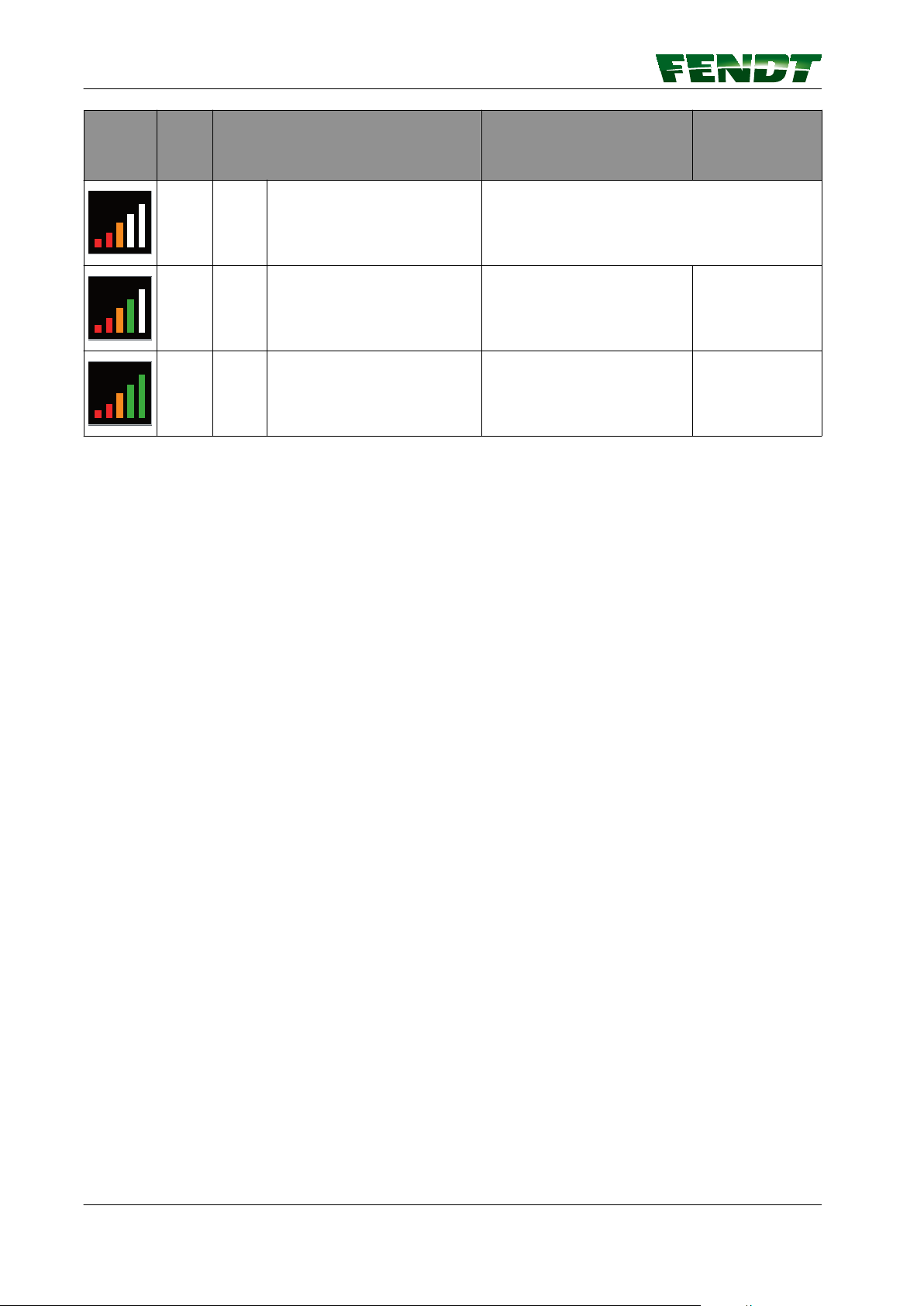
5.2.5 Novatel bar indicator, Trimble
NOTE:
Automatic wayline guidance can only be activated when at least three bars are displayed.
The accuracy of positioning is dependent upon the positions of the satellites relative to each other and the
position of the receiver, as well as the accuracy of time measurement and the runtime.
At favourable angles (~ 90°), the accuracy of measurement will be greater than at acute angles or angles of
approx. 180°.
HDOP (Horizontal Dilution of Precision)
The HDOP value is a measure of measured value scatter; the lower the value, the lower the degree of
measurement error.
SV
SV indicates the number of satellites used.
Bar
indicato
r
GNSS Correction signal HDOP
NOK NOK - - -
SV
OK NOK only if fallback is deactivated
OK OK
VarioGuide 47
438.020.070.012
Page 48
5. Map view
Bar
indicato
r
GNSS Correction signal HDOP
SV
OK OK every over 3 bars
OK OK every =< 1.5 >= 6
OK OK every =< 1.3 >= 7
48 VarioGuide
438.020.070.012
Page 49

5.3 Functions
5.3.1 Set markers
Procedure
1.
Press soft key , current position will be
saved and the pop-up shown below will
appear.
Select marker color
2.
5. Map view
Fig. 5
NOTE: A number ID starting at 1 is also
assigned for each individual marker color.
The name of the marker can be changed in
the marker settings menu.
3.
Confirm with . The pop-up will close
Fig. 6
VarioGuide 49
438.020.070.012
Page 50

5. Map view
5.3.2 Marker settings
Marker selection
Press the softkey (C) in full-screen mode to open a
selection list featuring the markers set for the
field. You can change the names of existing
markers and delete existing markers in this list.
5.3.3 Worked area settings
Fig. 7
Fig. 8
(A) Worked areas
Activate/Deactivate
The area colored green on the map shows the processed area. This processed area is linked to the Trigger
Settings page in VarioDoc/VarioGuide. The processed area is displayed on the map depending on the way
in which the settings have been set and if they have been set at all.
50 VarioGuide
438.020.070.012
Page 51

Procedure
Press soft key (D) and a pop-up appears.
1.
Color settings for processed area.
Press soft key (A) or (B) to activate manual or
2.
automatic color selection.
(A) MAN/AUTO softkey
(B) Manual color selection softkey
(C) Delete the area marker in the current
field
5. Map view
Fig. 9
Delete the area marker in the current field
Press soft key (C) and a pop-up appears.
3.
Fig. 10
Fig. 11
VarioGuide 51
438.020.070.012
Page 52

5. Map view
4.
Press the soft key , the area marker in the
current field is deleted and the pop-up
closes.
Manual color selection
Press soft key (B) and a pop-up appears.
5.
Fig. 12
Select the setting option:
6.
° Soft key (A) to change between manual
and automatic color display
°
(I) is the setting for the number of normalcolored waylines between two
contrasting waylines
° Soft key (J) for contrast color selection
° (K) is the setting for the wayline number;
starts from color change
NOTE: Using these setting options, you
can highlight the area that contains
tramlines in a different color.
Fig. 13
Fig. 14
52 VarioGuide
438.020.070.012
Page 53

Table of contents
6. VarioGuide components and calibrations
6.1 Calibrations .............................................................55
6.1.1 Calibrate steering angle sensor and steering valve ..............................55
VarioGuide 53
438.020.070.012
Page 54

Table of contents
54 VarioGuide
438.020.070.012
Page 55

6. VarioGuide components and calibrations
6.1 Calibrations
6.1.1 Calibrate steering angle sensor and steering valve
WARNING:
Hazard from automatic deflection of the front wheels Risk of injury and death! Material
damage is possible. During calibration check that there are no people or objects within
the steering area!
NOTE:
The steering angle sensor and steering valve must be calibrated before being used for the first time and
whenever the E-box is replaced.
NOTE:
It is recommended that the steering angle sensor and steering valve are calibrated when:
• The tractor does not drive straight along the way-lines
•
Other steering problems (e.g. tractor begins to sway) occur
NOTE:
If required, calibrate the front axle suspension (please speak to your Fendt dealer).
Calibrating the steering angle sensor (2401)
NOTE:
To operate the automatic track guidance, it is essential that the steering angle sensor is calibrated.
Proceed as follows:
• Operate the hand brake.
• Start engine.
Confirm the warning and fault messages
displayed on the instrument panel with ESC.
Fig. 1
Press RETURN; the first main menu level
appears on the multiple display.
Press one of the buttons repeatedly until
symbol (A) flashes.
Press RETURN; the second main menu level
appears on the multiple display.
Fig. 2
VarioGuide 55
438.020.070.012
Page 56

6. VarioGuide components and calibrations
Press one of the buttons repeatedly until the
symbol (A) flashes.
Confirm with RETURN.
Press one of the buttons repeatedly until the
symbol (A) flashes.
Confirm with RETURN.
Fig. 3
Input code 2401.
Press one of the buttons until the desired
number is displayed.
Confirm with RETURN.
Turn steering wheel against the left steering lock
and hold.
Confirm with RETURN.
Fig. 4
Fig. 5
Fig. 6
56 VarioGuide
438.020.070.012
Page 57

Turn steering wheel against the right steering lock
and hold.
Confirm with RETURN.
Release hand brake and drive the tractor forwards
slowly, keeping the wheels straight.
NOTE:
This calibration is an important requirement for
ensuring correct way-line guidance.
Confirm with RETURN.
6. VarioGuide components and calibrations
Fig. 7
If calibration is completed without errors, O.K.
appears and the new sensor settings are saved.
NOTE:
Settings are only stored when ignition key has
been turned to "0" position.
Wait for at least 30 seconds before switching on
ignition again!
If incorrect values are detected or the conditions
are not met, the message ERROR appears.
2401 = calibration code
FXX = fault code
Fig. 8
Fig. 9
Fig. 10
VarioGuide 57
438.020.070.012
Page 58

6. VarioGuide components and calibrations
Fault code Cause
F01
F08
F09
F10
F11
F12
F13
Preliminary conditions not satisfied
Calibration taking too long (more than 30 seconds)
User terminated calibration with ESC
Plausibility: "Center position" signal
Plausibility: "Left stop" signal
Plausibility: "Right stop" signal
Plausibility: Calibrated values match
NOTE:
If incorrect values are found, contact your Fendt dealer.
Calibrating VarioGuide steering valve (2403)
WARNING:
Hazard from automatic deflection of the front wheels Risk of injury and death! Material
damage is possible. During calibration check that there are no people or objects within
the steering area!
NOTE:
During calibration, the valve slider free travel is determined.
NOTE:
To operate the automatic track guidance, it is essential to calibrate the steering valve.
Please note:
• Do not leave operator's seat (seat contact
switch).
•
Start engine.
• Tractor stationary.
• Point wheels straight ahead.
• Do not move the steering wheel.
Confirm the warning and fault messages
displayed on the instrument panel with ESC.
Fig. 11
58 VarioGuide
438.020.070.012
Page 59

Press RETURN; the first main menu level
appears on the multiple display.
Press one of the buttons repeatedly until
symbol (A) flashes.
Press RETURN; the second main menu level
appears on the multiple display.
Press one of the buttons repeatedly until the
symbol (A) flashes.
Confirm with RETURN.
6. VarioGuide components and calibrations
Fig. 12
Press one of the buttons repeatedly until the
symbol (A) flashes.
Confirm with RETURN.
Input code 2403.
Press one of the buttons until the desired
number is displayed.
Confirm with RETURN.
Fig. 13
Fig. 14
Fig. 15
VarioGuide 59
438.020.070.012
Page 60

6. VarioGuide components and calibrations
The image shown opposite is displayed.
NOTE:
• The calibration runs automatically (approx. 5
minutes max.)
•
Do not actuate steering.
• Do not leave operator's seat (seat contact
switch).
The image shown opposite is displayed.
Fig. 16
If calibration is completed without errors, O.K.
appears and the new sensor settings are saved.
NOTE:
Settings are only stored when ignition key has
been turned to "0" position.
Wait for at least 30 seconds before switching on
ignition again!
If incorrect values are detected or the conditions
are not met, the message ERROR appears.
2403 = calibration code
FXX = fault code
Fig. 17
Fig. 18
Fig. 19
60 VarioGuide
438.020.070.012
Page 61

Fault code Cause
6. VarioGuide components and calibrations
F01
F02
F03
F06
F07
F08
F09
F11
F12
Preliminary conditions not satisfied
Front wheels are not straight
Manual steering wheel actuation during calibration
No movement in direction "steering to left"
No movement in direction "steering to right"
Calibration taking too long
User terminated calibration with ESC
Plausibility: Signal in direction "steering to left"
Plausibility: Signal in direction "steering to right"
NOTE:
If incorrect values are found, contact your FENDT dealer.
VarioGuide 61
438.020.070.012
Page 62

6. VarioGuide components and calibrations
62 VarioGuide
438.020.070.012
Page 63

Table of contents
7. Start-up
7.1 Load implement .........................................................65
7.1.1 Caution .............................................................65
7.1.2 Load implement settings (7" terminal) .......................................65
7.1.3 Load implement settings (10.4" terminal) .....................................66
7.2 Create implement .......................................................67
7.2.1 Call up implement settings on 7" ..........................................67
7.2.2 Call up implement settings on 10.4" ........................................68
7.2.3 Front-mounted implement ...............................................69
7.2.3.1 Install front-mounted implement ....................................69
7.2.3.2 Determine the working width, navigation point distance and coupling length ....70
7.2.3.3 Set the working width of the front-mounted implement ...................71
7.2.3.4 Set the navigation point of the front-mounted implement ..................72
7.2.3.5 Set the coupling length for the front-mounted implement .................73
7.2.3.6 Set the center of the front-mounted implement .........................74
7.2.3.7 Set the trigger for the front-mounted implement ........................75
7.2.4 Rear-mounted implement ................................................76
7.2.4.1 Install rear-mounted implement .....................................76
7.2.4.2 Determine the working width, navigation point distance and coupling length ....77
7.2.4.3 Set the navigation point of the rear-mounted implement ...................78
7.2.4.4 Set the coupling length for the rear-mounted implement ..................79
7.2.4.5 Set the center of the rear-mounted implement .........................80
7.2.4.6 Set the trigger for the rear-mounted implement .........................81
7.3 Save mounted implement data ...........................................82
7.3.1 Save implement on stopping .............................................82
7.4 Exchange implement data and field data ..................................84
7.4.1 Plug in the USB stick and call up data exchange ................................84
7.4.1.1 Insert USB stick ................................................84
7.4.1.2 Call up data exchange on 10.4" .....................................84
7.4.2 Transfer implement data and field data to the USB stick ..........................85
7.4.2.1 Select and transfer all data .........................................86
7.4.3 Transfer implement and field data from the USB stick to the terminal ................87
7.4.3.1 Select and transfer all data .........................................89
7.5 Correction signals .......................................................90
7.5.1 Overview of correction signals depending on the receiver ........................90
7.6 Submeter range with NovAtel receiver ....................................91
7.6.1 Autonomous .........................................................91
7.6.2 EGNOS / WAAS ......................................................92
7.7 Centimeter range with NovAtel receiver ..................................93
7.7.1 FENDT base station ....................................................93
7.7.1.1 Configure the FENDT base station correction signal ......................93
7.7.1.2 Fallback: FENDT base station .......................................94
7.7.2 External station .......................................................95
7.7.2.1 Configure the external station correction signal ..........................95
7.7.2.2 External fallback station ...........................................96
7.7.3 RTK network (internal mobile radio modem) ...................................96
7.7.3.1 Configure the internal mobile modem correction signal ....................96
7.7.3.2 Activate/deactivate internal mobile modem fallback .......................98
7.7.4 RTK network (external mobile radio modem) ..................................98
7.7.4.1 Configure the external mobile modem correction signal ....................98
VarioGuide 63
438.020.070.012
Page 64

Table of contents
7.8 Submeter range with Trimble receiver ................................... 100
7.8.1 Autonomous ........................................................ 100
7.8.2 EGNOS / WAAS ......................................................101
7.8.3 RangePoint RTX ......................................................102
7.9 Decimeter range with Trimble receiver ...................................103
7.9.1 CenterPoint RTX Satellite ............................................... 103
7.9.1.1 Set correction signal for Centerpoint RTX Satellite .......................103
7.9.1.2 Fallback for Centerpoint RTX Satellite ................................104
7.10 Centimeter range with Trimble receiver .................................105
7.10.1 FENDT base station .................................................. 105
7.10.1.1 Configure the FENDT base station correction signal — Trimble AG-715 450
MHz radio modem ....................................................105
7.10.1.2 Configure the FENDT base station correction signal (Trimble 900 MHz) ...... 106
7.10.2 RTK network (internal GSM/GPRS modem) ................................. 107
7.10.2.1 Configure the internal mobile modem correction signal (GSM/GPRS) ........ 107
7.10.3 RTK network (external mobile radio modem) ................................ 108
7.10.3.1 Configure the external mobile modem correction signal ..................108
7.10.4 Trimble receiver settings ...............................................109
7.10.4.1 xFill settings ................................................. 109
7.11 Field Settings ......................................................... 111
7.11.1 Add field .......................................................... 111
7.11.2 Record field boundary .................................................112
7.11.3 Record/manage obstacles ..............................................115
7.12 Way-line ..............................................................119
7.12.1 Create and save way line ..............................................119
7.12.2 Path to path distance ................................................. 124
7.13 Check system ......................................................... 125
7.13.1 Check system info/system status ........................................125
7.14 Activate VarioGuide system ............................................127
7.14.1 Switch on automatic way line guidance ....................................127
7.15 Adjust way line ........................................................128
7.15.1 Way line offset ..................................................... 128
7.16 Headland settings ..................................................... 129
7.16.1 Headland settings ................................................... 129
7.16.2 Headland management TI/AutoTI ........................................ 131
7.17 Operation with the base station ........................................ 133
7.17.1 Brief description .................................................... 133
7.17.2 Scope of delivery and accessories ........................................133
7.17.3 LED and keys on the base station ........................................ 136
7.17.4 Initial start-up .......................................................137
7.17.5 Operating modes .................................................... 138
7.17.6 Start-up ........................................................... 138
7.17.7 Set the base station channel on the tractor ................................. 139
7.17.8 Operate base station with external battery ..................................141
64 VarioGuide
438.020.070.012
Page 65

7. Start-up
7.1 Load implement
7.1.1 Caution
WARNING:
The tractor should only be operated with the automatic steering system when it is used in
an area well away from buildings, other machinery and people.
NOTE:
A quick turn of the steering wheel de-activates automatic steering.
7.1.2 Load implement settings (7" terminal)
NOTE:
This function can be used to load settings for an implement that has already been created, and to add the
settings in the VarioGuide (implement settings and way-line distance). A new implement can also be
created.
Call up the management main menu (7")
Applications main menu
The view shown opposite appears once button (D)
has been pressed on the external control panel.
Select management (softkey G).
(D) Application selection control panel
(G) Management softkey
Load implement settings
• When softkey (A, see #unique_42/
unique_42_Connect_42_T021795-FIE910) is
pressed, the pop-up shown opposite appears.
Select implement and confirm.
Fig. 1
Fig. 3
VarioGuide 65
438.020.070.012
Page 66

2011
35101011
1024
Verwaltung Info
D
7. Start-up
7.1.3 Load implement settings (10.4" terminal)
NOTE:
This function can be used to load settings for an implement that has already been created, and to add the
settings in the VarioGuide (implement settings and way-line distance). A new implement can also be
created.
Call up the management main menu (10.4"
terminal)
Information management
(D) Management
Load implement settings
• When softkey (A, see #unique_42/
unique_42_Connect_42_T021795-FIE910) is
pressed, the pop-up shown opposite appears.
Select implement and confirm.
Fig. 4
Fig. 6
66 VarioGuide
438.020.070.012
Page 67

7.2 Create implement
7.2.1 Call up implement settings on 7"
Procedure
7. Start-up
Fig. 7
Press the positioning button on the external control panel.
1.
Under "Management info", press the soft key for the on-board computer; "On-board computer" page
2.
is displayed.
On the "On-board computer" page, press the soft key for the trigger settings; "Trigger settings" page
3.
is displayed.
On the "Trigger settings" page, press the "Front-mounted implement" soft key; the "Implement
4.
settings" page is displayed.
VarioGuide 67
438.020.070.012
Page 68

7. Start-up
7.2.2 Call up implement settings on 10.4"
Procedure
Fig. 8
On the "Tractor Info" page, press the softkey for VarioDoc, and "VarioDoc Info" is displayed In
1.
"VarioDoc Info", press the VarioDoc softkey, and the "VarioDoc Main Page" appears.
In "VarioDoc Main Page", press the soft key for the on-board computer; the "On-board computer" page
2.
is displayed
On the "On-board computer" page, press the trigger settings; the "Trigger settings" page is displayed
3.
On the "Trigger settings" page, press the "Front-mounted implement" soft key; the "Implement
4.
settings" page is displayed.
68 VarioGuide
438.020.070.012
Page 69

7.2.3 Front-mounted implement
Geräteanbauposition auswählen
Heck
7.2.3.1 Install front-mounted implement
Procedure
Press softkey (A). A pop-up appears.
1.
7. Start-up
Select front-mounted implement.
2.
Fig. 9
Fig. 10
VarioGuide 69
438.020.070.012
Page 70

7. Start-up
3.
Assign a name and press to confirm.
Fig. 11
7.2.3.2 Determine the working width, navigation point distance and coupling length
Working width Center Navigation point Coupling length
Actual working width of
the implement
Movement of the
implement from the
center (e.g. for mowers)
Distance of the
horizontal rotational axis
of the implement from
the lower link hooks
Distance of the
processing area of the
implement from the
lower link hooks
Procedure
Start work and drive approx. 10 m.
1.
Measure the processed width (working width).
2.
Measure the length between the navigation point of the implement and the attachment hook
3.
NOTE:
The navigation point is the point on the implement that follows the wayline.
Measure the length between the start of the processed area and the attachment hook of the front
4.
power lift
NOTE: If the mark is to be created at the end of the implement, measure from this point to the end
of the implement.
70 VarioGuide
438.020.070.012
Page 71

7.2.3.3 Set the working width of the front-mounted implement
Procedure
Select the working width field (A) by touch or
1.
via the external control panel.
Set the processed width value via the
2.
external control panel.
7. Start-up
Fig. 12
VarioGuide 71
438.020.070.012
Page 72

7. Start-up
7.2.3.4 Set the navigation point of the front-mounted implement
Procedure
Select the navigation point field (A) by touch
1.
or via the external control panel.
Set the navigation point distance via the
2.
external control panel.
Fig. 13
72 VarioGuide
438.020.070.012
Page 73

7.2.3.5 Set the coupling length for the front-mounted implement
Procedure
Select the coupling length field (A) by touch
1.
or with the external control panel.
Set the coupling length distance via the
2.
external control panel.
7. Start-up
Fig. 14
VarioGuide 73
438.020.070.012
Page 74

7. Start-up
7.2.3.6 Set the center of the front-mounted implement
Procedure
Select the center field (A) by touch or via the
1.
external control panel.
Set the center via the external control panel.
2.
NOTE:
Only set the center if the mounted
implement deviates from the center.
Fig. 15
74 VarioGuide
438.020.070.012
Page 75

7.2.3.7 Set the trigger for the front-mounted implement
Procedure
Select and activate the trigger by touch or via
the external control panel.
NOTE:
Measurement takes place once all activated
trigger conditions are fulfilled simultaneously.
(A) Toggle switch Auto/I (ON)
NOTE:
If toggle switch (A) is set to I, the
distance and area are always
measured, except when the on-board
computer is paused. The other buttons
are grayed out.
If toggle switch (A) is set to AUTO, the
distance and area measurement
depends on triggers (B) to (F).
(B) Front power lift trigger OFF/ON
(C) Front PTO trigger OFF/ON
(D) EHS valve trigger OFF/ON
(E) External counter trigger OFF/ON
(F) VarioGuide trigger OFF/ON
(H) Jump back one menu level
7. Start-up
Fig. 16
VarioGuide 75
438.020.070.012
Page 76

Geräteanbauposition auswählen
Heck
7. Start-up
7.2.4 Rear-mounted implement
7.2.4.1 Install rear-mounted implement
Procedure
Press softkey (A). A pop-up appears.
1.
Select the rear-mounted implement.
2.
Fig. 17
Fig. 18
76 VarioGuide
438.020.070.012
Page 77

Select the trailer type.
Gezogenes Gerät
Heckkraftheber
Heckgeräteanbauposition auswählen
3.
Assign a name and press to confirm.
4.
7. Start-up
Fig. 19
Fig. 20
7.2.4.2 Determine the working width, navigation point distance and coupling length
Working width Center Navigation point Coupling length
Actual working width of
the implement
Movement of the
implement from the
center (e.g. for mowers)
Distance of the
horizontal rotational axis
of the implement from
the lower link hooks
Distance of the
processing area of the
implement from the
lower link hooks
VarioGuide 77
438.020.070.012
Page 78

7. Start-up
Procedure
Start work and drive approx. 10 m.
1.
Measure the processed width (working width).
2.
Measure the length between the navigation point of the implement and the attachment hook
3.
NOTE:
The navigation point is the point on the implement that follows the wayline.
Measure the length between the start of the processed area and the attachment hook of the front
4.
power lift
NOTE: If the mark is to be created at the end of the implement, measure from this point to the end
of the implement.
7.2.4.3 Set the navigation point of the rear-mounted implement
Procedure
Select the navigation point field (A) by touch
1.
or via the external control panel.
Set the navigation point distance via the
2.
external control panel.
Fig. 21
78 VarioGuide
438.020.070.012
Page 79

7.2.4.4 Set the coupling length for the rear-mounted implement
Procedure
Select the coupling length field (A) by touch
1.
or with the external control panel.
Set the coupling length distance via the
2.
external control panel.
7. Start-up
Fig. 22
VarioGuide 79
438.020.070.012
Page 80

7. Start-up
7.2.4.5 Set the center of the rear-mounted implement
Procedure
Select the center field (A) by touch or via the
1.
external control panel.
Set the center via the external control panel.
2.
NOTE:
Only set the center if the mounted
implement deviates from the center.
Fig. 23
80 VarioGuide
438.020.070.012
Page 81

7.2.4.6 Set the trigger for the rear-mounted implement
Procedure
Select and activate the trigger by touch or via
the external control panel.
NOTE:
Measurement takes place once all activated
trigger conditions are fulfilled simultaneously.
(A) Toggle switch Auto/I (ON)
NOTE:
If toggle switch (A) is set to I, the
distance and area are always
measured, except when the on-board
computer is paused. The other buttons
are grayed out.
If toggle switch (A) is set to AUTO, the
distance and area measurement
depends on triggers (B) to (F).
(B) Rear power lift trigger OFF/ON
(C) Rear PTO trigger OFF/ON
(D) EHS valve trigger OFF/ON
(E) External counter trigger OFF/ON
(F) VarioGuide trigger OFF/ON
(H) Jump back one menu level
7. Start-up
Fig. 24
VarioGuide 81
438.020.070.012
Page 82

7. Start-up
7.3 Save mounted implement data
7.3.1 Save implement on stopping
NOTE:
This function can be used to save the current settings for an implement (incl. the implement settings and
the track distance from VarioGuide).
Save the current implement settings with the same name
If an implement has been loaded and one or more
settings then changed, the page shown opposite
appears when the engine is switched off.
• The current settings are saved under the same
name with the key.
• The terminal then switches off.
Save the current settings with a different name
Press softkey .
Fig. 25
Fig. 26
82 VarioGuide
438.020.070.012
Page 83

• The pop-up shown opposite appears.
• To save the current implement settings under
an existing name, select name and confirm.
• To save the current implement settings with a
new name, select a blank line, specify a name
using the keyboard and confirm.
• The terminal then switches off.
NOTE:
This procedure is used to create a new implement;
the original implement remains unchanged.
7. Start-up
Fig. 27
Fig. 28
VarioGuide 83
438.020.070.012
Page 84

2011
35101011
1024
1 2
3
7. Start-up
7.4 Exchange implement data and field data
7.4.1 Plug in the USB stick and call up data exchange
Implement data and field data can be transferred from tractor to tractor using a USB stick (when using
VarioGuide).
The USB stick can also be used to back up the implement data and field data, e.g. before replacing the
terminal.
7.4.1.1 Insert USB stick
Procedure
Pull flap (A) open to reveal the USB ports.
1.
Insert USB stick into the appropriate port.
2.
Fig. 29
7.4.1.2 Call up data exchange on 10.4"
Fig. 30
Press the "Management main menu" soft key on the "Management info" page, the "Management
1.
main menu" page is displayed
On the "Management main menu" page, press the soft key for the data exchange; the "Data
2.
exchange" page is displayed.
84 VarioGuide
438.020.070.012
Page 85

7.4.2 Transfer implement data and field data to the USB stick
H
B
A
Select and transfer individual data
Procedure
Using the soft key, select the data to be
1.
transferred:
(A) Field data
(B) Implement data
Select field data or implement data by touch
2.
or with the external control panel.
7. Start-up
Fig. 31
VarioGuide 85
438.020.070.012
Page 86

I
H
B
A
7. Start-up
Press the soft key (I); individual data is
3.
transferred to the USB stick.
NOTE:
If there is identical data on the USB stick, a
popup appears and asks whether the existing
file should be replaced or renamed.
NOTE:
Before the transfer of field data, a popup
appears and asks whether processed areas
should be transferred as well. If so, the
transfer process may take a few minutes.
NOTE:
The transferred data can then be seen in the
bottom display.
7.4.2.1 Select and transfer all data
Procedure
Using the soft key, select the data to be
1.
transferred:
(A) Field data
(B) Implement data
Fig. 32
Fig. 33
86 VarioGuide
438.020.070.012
Page 87

Press the soft key (K); all data is transferred
K
2.
to the USB stick.
NOTE:
If there is identical data on the USB stick, a
popup appears and asks whether the existing
file should be replaced or renamed.
NOTE:
Before the transfer of field data, a popup
appears and asks whether processed areas
should be transferred as well. If so, the
transfer process may take a few minutes.
NOTE:
The transferred data can then be seen in the
bottom display.
7. Start-up
Fig. 34
7.4.3 Transfer implement and field data from the USB stick to the terminal
Select and transfer individual data
VarioGuide 87
438.020.070.012
Page 88
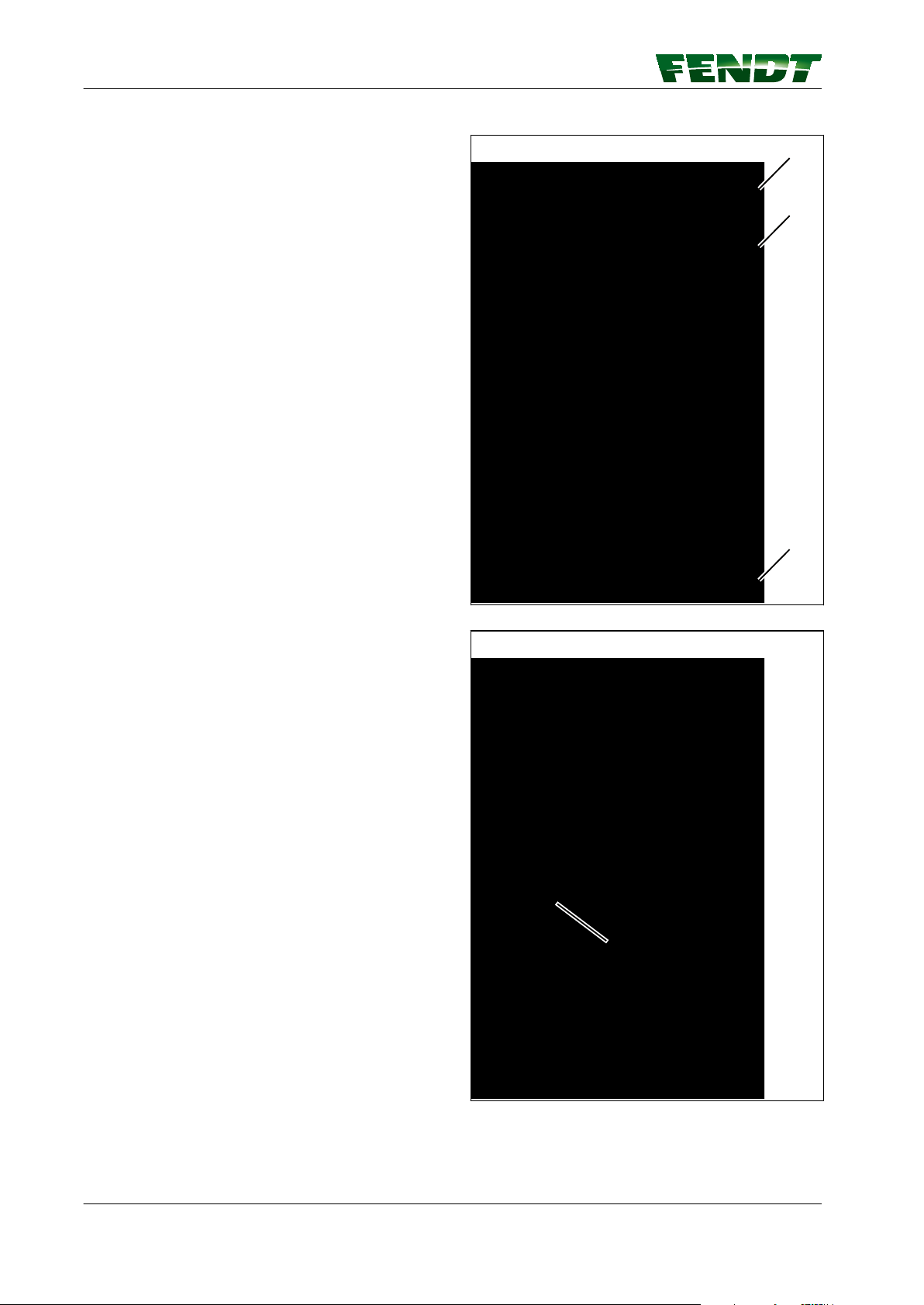
H
B
A
J
7. Start-up
Procedure
Using the soft key, select the data to be
1.
transferred:
(A) Field data
(B) Implement data
Select field data or implement data by touch
2.
or with the external control panel.
Press the soft key (J), individual data is
3.
transferred from the USB stick to the
terminal.
NOTE:
If there is identical data on the terminal, a
popup appears and asks whether the existing
file should be replaced or renamed.
NOTE:
The transferred data can then be seen in the
bottom display.
Fig. 35
Fig. 36
88 VarioGuide
438.020.070.012
Page 89

7.4.3.1 Select and transfer all data
H
B
A
L
Procedure
Using the soft key, select the data to be
1.
transferred:
(A) Field data
(B) Implement data
7. Start-up
Press the soft key (L); all data is transferred
2.
from the USB stick to the terminal.
NOTE:
If there is identical data on the terminal, a
popup appears and asks whether the existing
file should be replaced or renamed.
NOTE:
The transferred data can then be seen in the
bottom display.
Fig. 37
Fig. 38
VarioGuide 89
438.020.070.012
Page 90

7. Start-up
7.5 Correction signals
7.5.1 Overview of correction signals depending on the receiver
Receiver type Accuracy Supported correction signal
Topcon AGI-4 Sub-meter Autonomous
EGNOS / WAAS
OMNISTAR VBS
Decimetre OMNISTAR HP /G2 / XP
Centimeter RTK base
SATEL 3AS radio modem
Topcon FH915 radio modem
External radio modem
RTK network
Internal GSM/GPRS modem
External mobile radio modem
NovAtel SMART6-L Sub-meter Autonomous
EGNOS / WAAS
Centimeter RTK base
SATEL EASy-Proof radio modem
RTK network
Internal GSM/GPRS modem
External mobile radio modem
Trimble AG382 Sub-meter Autonomous
EGNOS / WAAS
RangePoint RTX
Decimetre Centerpoint RTX Satellite
Centimeter RTK base
Trimble AG-715 450MHz radio
Trimble AG-715 900MHz radio
External radio modem
modem
modem
SATEL EASy-Proof radio modem
External radio modem
RTK network
Internal GSM/GPRS modem
External mobile radio modem
90 VarioGuide
438.020.070.012
Page 91

7.6 Submeter range with NovAtel receiver
7.6.1 Autonomous
NOTE:
The position is determined without correction
signals, using only GPS and GLONASS satellites
(for regions in which there is no correction signal
or none can be received).
7. Start-up
Fig. 39
VarioGuide 91
438.020.070.012
Page 92

7. Start-up
7.6.2 EGNOS / WAAS
Set correction signal
Select the correction signal via the "Signal
Type" selection field.
Fig. 40
Display
Satellite receiver Designation of the installed receiver
Signal type The correction signal source can be selected here
Accuracy Bar indicator and decimal value of static accuracy
Signal lag Specifies the time in s taken to receive the correction signal update. If 999 is
shown here, the correction signal cannot be currently received.
Connection status Specifies the connection status of the GNSS receiver to the source of the
correction data (e.g. connected, update required, expired). The tick shows
whether the GNSS receiver is currently connected to the correction data
source.
Authorisation level Specifies the accuracy level of the GNSS receiver (depending on the hardware
modules installed in the receiver)
92 VarioGuide
438.020.070.012
Page 93

7.7 Centimeter range with NovAtel receiver
7.7.1 FENDT base station
7.7.1.1 Configure the FENDT base station correction signal
Procedure
Select the correction signal via the "Signal
1.
Type" selection field.
NOTE:
Correction signal activation can only be
received if a green tick appears in the
connection status. Where applicable, verify
channel, frequency and signal format.
Select 'Fendt Station' under station type
2.
Set the frequency
3.
Set the channel spacing
4.
Set the error correction
5.
Select signal format.
6.
7. Start-up
Fig. 41
Display
Satellite receiver Designation of the installed receiver
Signal type The correction signal source can be selected here
Base Type Fendt Base
Accuracy Bar indicator and decimal value of static accuracy
Signal lag Specifies the time in s taken to receive the correction signal update. If 999 is
shown here, the correction signal cannot be currently received.
Connection status Specifies the connection status of the GNSS receiver to the source of the
correction data (e.g. connected, update required, expired). The tick shows
whether the GNSS receiver is currently connected to the correction data
source.
Authorisation level Specifies the accuracy level of the GNSS receiver (depending on the hardware
modules installed in the receiver)
Distance to Base Distance in m
VarioGuide 93
438.020.070.012
Page 94

7. Start-up
Display
Frequency Set the frequency assigned to you by your country's regulatory authority.
Channel spacing Set the channel spacing here: 25 kHz with 6.25 kHz spacing/205 kHz with
10 kHz spacing/12.5 kHz with 6.25 kHz spacing
Error correction Set the error correction here: ON/OFF
Signal format Select the signal format: CMR/RTCM 2.3/RTCM 3.1
7.7.1.2 Fallback: FENDT base station
Procedure
Press toggle switch (A), the fallback option
will either be activated or deactivated.
NOTE:
Enabling this function allows wayline
guidance to a lower degree of accuracy.
Fig. 42
94 VarioGuide
438.020.070.012
Page 95

7.7.2 External station
7.7.2.1 Configure the external station correction signal
Procedure
Select the correction signal via the "Signal
1.
Type" selection field.
NOTE:
Correction signal activation can only be
received if a green tick appears in the
connection status. Where applicable, verify
channel, frequency and signal format.
Select 'External Station' under station type
2.
Configure baud rate
3.
Select parity
4.
Select signal format
5.
7. Start-up
Fig. 43
Display
Satellite receiver Designation of the installed receiver
Signal type The correction signal source can be selected here
Base Type External station
Accuracy Bar indicator and decimal value of static accuracy
Signal lag Specifies the time in s taken to receive the correction signal update. If 999 is
shown here, the correction signal cannot be currently received.
Connection status Specifies the connection status of the GNSS receiver to the source of the
correction data (e.g. connected, update required, expired). The tick shows
whether the GNSS receiver is currently connected to the correction data
source.
Authorisation level Specifies the accuracy level of the GNSS receiver (depending on the hardware
modules installed in the receiver)
Distance to Base Distance in m
VarioGuide 95
438.020.070.012
Page 96

7. Start-up
Display
Baud rate Setting data for external radio modem
Parity Setting data for external radio modem
Signal format Setting data for external radio modem
7.7.2.2 External fallback station
Procedure
Press toggle switch (A), the fallback option
will either be activated or deactivated.
NOTE:
Enabling this function allows wayline
guidance to a lower degree of accuracy.
Fig. 44
7.7.3 RTK network (internal mobile radio modem)
7.7.3.1 Configure the internal mobile modem correction signal NOTE:
After the ignition has been switched OFF/ON, the system connects to the GSM/GPRS network
automatically and without further notice, provided that a connection was established before the ignition
was switched off. Please note that this action may result in data charges.
96 VarioGuide
438.020.070.012
Page 97

Set correction signal
Select the correction signal via the "Signal
1.
Type" selection field.
Select 'Internal Modem' as the modem type
2.
Select "Dial connection (GSM)" or "Data
3.
connection" as the connection type
Select signal format
4.
7. Start-up
Fig. 45
Display
Satellite receiver Designation of the installed receiver
Signal type The correction signal source can be selected here
Modem type Internal modem
Connection type Dial connection (GSM) / Data connection
Signal strength Mobile communications signal strength
Accuracy Bar indicator and decimal value of static accuracy
Signal lag Specifies the time in s taken to receive the correction signal update. If 999 is
shown here, the correction signal cannot be currently received.
Connection status Specifies the connection status of the GNSS receiver to the source of the
correction data (e.g. connected, update required, expired). The tick shows
whether the GNSS receiver is currently connected to the correction data
source.
Authorisation level Specifies the accuracy level of the GNSS receiver (depending on the hardware
modules installed in the receiver)
Signal format from the correction signal provider
VarioGuide 97
438.020.070.012
Page 98

7. Start-up
7.7.3.2 Activate/deactivate internal mobile modem fallback
Procedure
Press toggle switch (A), the fallback option
will either be activated or deactivated
NOTE:
Enabling this function allows wayline
guidance to a lower degree of accuracy.
Fig. 46
7.7.4 RTK network (external mobile radio modem)
7.7.4.1 Configure the external mobile modem correction signal NOTE:
After the ignition has been switched OFF/ON, the system connects to the GSM/GPRS network
automatically and without further notice, provided that a connection was established before the ignition
was switched off. Please note that this action may result in data charges.
98 VarioGuide
438.020.070.012
Page 99
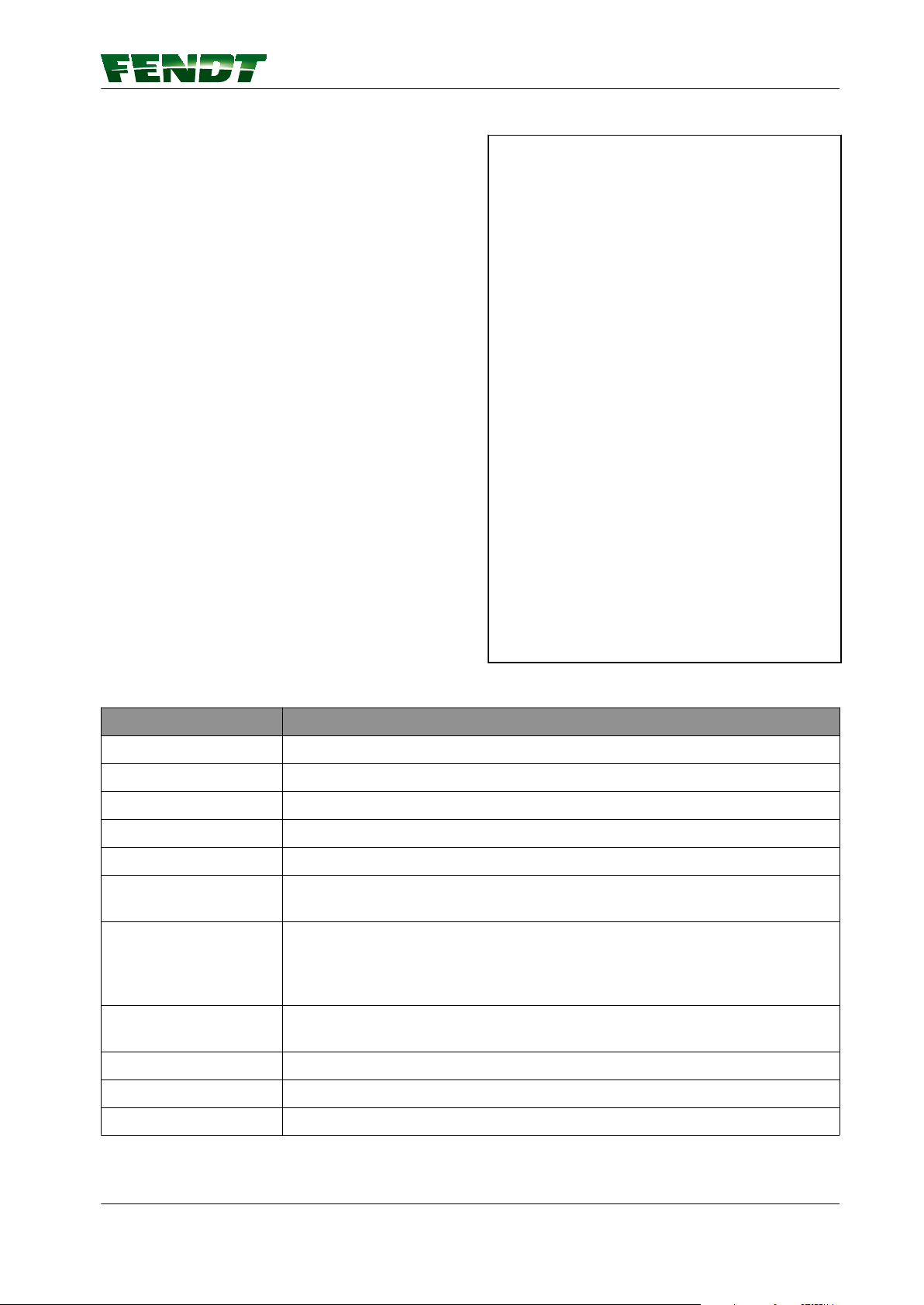
Procedure
Select the RTK Network correction signal
1.
under 'Signal Type'.
Select the modem type "External modem"
2.
Enter the baud rate
3.
Select parity
4.
Select signal format
5.
7. Start-up
Fig. 47
Display
Satellite receiver Designation of the installed receiver
Signal type The correction signal source can be selected here
Modem type External modem
Signal strength Mobile communications signal strength
Accuracy Bar indicator and decimal value of static accuracy
Signal lag Specifies the time in s taken to receive the correction signal update. If 999 is
shown here, the correction signal cannot be currently received.
Connection status Specifies the connection status of the GNSS receiver to the source of the
correction data (e.g. connected, update required, expired). The tick shows
whether the GNSS receiver is currently connected to the correction data
source.
Authorisation level Specifies the accuracy level of the GNSS receiver (depending on the hardware
modules installed in the receiver)
Baud rate 9600 / 19200 / 38400 / 57600 / 115200
Parity Invalid/none/even/odd
Signal format CMR/RTCM 2.3/RTCM 3.1
VarioGuide 99
438.020.070.012
Page 100

7. Start-up
7.8 Submeter range with Trimble receiver
7.8.1 Autonomous
Autonomous Trimble AG-382
NOTE:
The position is determined without correction
signals, using only GPS and GLONASS satellites
(for regions in which there is no correction signal
or none can be received).
Fig. 48
100 VarioGuide
438.020.070.012
 Loading...