

Page 1
Werkstatthandbuch
Workshopmanual
Manuel de réparation
Manuel d´atelier
Manuale per I´officina
Motor
Engine
Moteur
Motore
MAN D 0836 LE (Mechanical part)
X990.005.039.010
Page 2

MAN D 0836 LE
Favorit 916 916/../3001Favorit 920 920/../3001Favorit 924 924/../3001Favorit 926 926/../3001-
Herausgegeben von der Abt. Kundendienst der Fa. ACGO GmbH & Co., Marktoberdorf
Alle Rechte vorbehalten – Printed in Germany. Diese Druckschrift darf ohne unsere schriftliche Genehmigung
Weder ganz noch auszugsweise vervielfältigt werden.
Published by the Service Division of ACGO GmbH & Co., Marktoberdorf
Copyright –All rights reserved – Printed in Germany. Rproduction of this publication, in whole or parts,
without our prior authorisation, is prohibited.
Peblié par le Service Aprés-vente de ACGO GmbH & Co., Marktoberdorf
Tous droits réservés – Printed in Germany Cette brochure ne peut être reproduite, ni totalement,
ni par extraits sans notre autorisation écrite.
Pubblicato dal reparto tecnico della ACGO GmbH & Co., Marktoberdorf
Tutti i dirette riservati – Printed in Germany La riproduzione die questo libro, sia completa che in parte
É vietata senza la nostra autorzzazione.
Redatto dal reparto assistenza della ditta ACGO GmbH & Co., Marktoberdorf
Tutti i diritti riservati - printed in Germany. Laa riproduzione di questo opuscolo, parziale o integrale,
non è ammessa senza autorizzazione scritta.
Page 3

WERKSTATTHANDBUCH
WORKSHOPMANUAL
MANUEL D´ATELIER
MANUAL DE TALLER
MANUALE PER L‘OFFICINA
MOTOR / ENGINE / MOTEUR / MOTORE
MAN D 0836 LE
(Mechanical part)
Ausgabe 05/2001
Xaver FENDT GmbH & CO.
Ein Unternehmen der AGCO-Corp.
Maschinen- und Schlepperfabrik, Marktoberdorf / Bayern Germany
Postfachadresse: D-87609 Marktoberdorf, Postfach 1155
Telefon (0 83 42) 77-0 Telefax (0 83 42) 77-2 22 (Kundendienst)
Bestell-Nr.
X 990.005.039.010
2672 C - en EKI 09/01 © Printed in Germany – All rights reserved
Page 4

VORWORT
Das vorliegende Werkstatthandbuch wurde für die
Reparaturwerkstätten unserer Vertretungen zusammengestellt und enthält alle Demontage- und Montagevorgänge, die im Zusammenhang mit Einstellarbeiten und der Auswechselung von Teilen
erforderlich ist.
Sind Teile auszuwechseln, so dürfen nur OriginalErsatzteile verwendet werden. Teile-Bestellungen
bitten wir unter Angabe der Fahrgestell-Nummer nach
den jeweils gültigen Ersatzteilunterlagen auf zugeben.
Es wird vorausgesetzt, daß diese Arbeiten von
Fachleuten ausgeführt werden; daher wurde auf die
Beschreibung allgemein bekannter Reparaturen
verzichtet.
Handelsübliche Werkzeuge und allgemeines Gerät,
das zur Ausrüstung einer Werkstatt gehört, wird
hierbei vorausgesetzt.
Spezialwerkzeuge sind auf das notwendige Maß
beschränkt und am Schluß des Buches in einer
Zusammenfassung gezeigt. Hinsichtlich der Pflegeund Wartungsarbeiten verweisen wir auf die Betriebsanleitungen.
Von den Werkstätten sind ie Technischen Daten zu
beachten.
Die einschlägigen Unfallverhütungsvorschriften sowie
die sonstigen allgemeinen anerkannten sicherheitstechnischen und arbeitsmedizinischen
Regeln sind einzuhalten.
Dieses Werkstatthandbuch unterliegt keinem Änderungsdienst, wir weisen aus diesem Grunde auf die
zusätzlich herauskommenden technischen Rundschreiben besonders hin. Bei Neuauflage eines
Werkstatthandbuches werden alle Änderungen
berücksichtigt und mit eingearbeitet.
Gegenüber Darstellungen und Angaben dieses
Werkstatthandbuches sind technische Änderungen,
die zur Verbesserung des Produktes notwendig
werden, vorbehalten. Nachdruck und Vervielfälti gung
jeglicher Art, auch auszugsweise, bedarf unserer
schriftlichen Genehmigung.
FOREWORD
This workshop manual was compiled for our agent´s
repair workshops and contains all the dismantling and
assembly procedures necessary in connection with
adjustments and replacement of parts.
If parts have to be renewed, only original replacement
parts may be used. Orders für parts must state the
chassis number and be in line with the latest parts
decomentation.
It is assumed that these repairs will be carried out by
skilled mechanics; descriptions of routine repair work
have, theerfore, been omitted.
It is furher assumed that the workshop concerned is
equipped with standard tools and has the normal
workshop facilities. The special tools are restricted to
the essential minimum and are shown in a summery
at the back of this manual.
Please refer to the Operating Instructions for details of
general maintenance and care operations.
Workshops must observe the technical data.
The accident prevention regulations and all other
generally recognized regulations on safety and
occupational medicine are to be observed.
This workshop manual is not subject to an updating
service. For this reason we draw your attention to the
supplementary technical circulars which are published
separately. New issues of a workshop manual
incorporate all the latest changes.
In view of continuous desing improvements or
changes, the technical specifications and the
illustrations shown in this Workshop Manual are
subject to alteration. Reprinting and reproduction, in
part or in whole, are subject to our written approval.
de/en
Page 5

AVANT PROPOS
Le présent Manuel de Réparation a été concupour
les Ateliers de Réparation de nos dépositaires et il
contient toutes les instructions de démontage et de
montage nécessitées par les travauc de réglade et
de remplacement des piéces.
Dés qu´il s´agit de remplacer des piéces, il faut
utiliser uniquement des piéces de rechange
originales. Pour commander les piéces de
rechange, nous prions de nous indiquer le numéro
du chassis et le numéro de référence de la piéce
concernée.
On considére que ces travaux sont effectués par
des spécialistes et c´est pourquoi les réparations
courantes ne sont pas décrites.
On considére également que l´on dispose des outils
classiques et de l´appareillage équipant
normalement un atelier.
Les outils spéciaux ont été réduits au strct
nécessaire et ils sont énumérés la fin du manuel.
En ce qui cincerne les travaux d´entretien, priére de
consulter les Instructions de Service.
Les ateliers de réparation devront tenir compte des
caractéristiques techniques.
Il convient de respecter les consignes générales de
sécurité et de prévention des accidents en vigueur.
Le présent Manuel de Réparation n´est soumit á
aucune midification, et c´est pourquoi il convient de
consulter les Circulaires Techniques publiées par la
suite. L´édition d´un nouveau Manuel de Réparation
tient compte de toutes les modification nécessaires.
Sous féserve de modifications techniques
nécessaires á lámélioration des produits présentés
par des illustrations et des indications référencées
dans ce Manuel d´Atelier.
Réimpression et reproduction meme partielle, quelle
qu´en soit la nature, interdtes sans l´autorisation
écrite de nos service.
PROLOGO
El presente Manual de Rparaciones ha sido
elaborado para los talleres de nuestros servicios
oficiales y comprende todos los trabjos de montaje
y desmontaje qu son necesarios para la sustitución
de piezas o trabajos de ajuste.
Cuando se sustituyan piezas deberán utilizarse
unicamente piezas de repuesto originales. Los
pedidos de las piezas de repuesto, sirvanse
hacerlos indicando el número de chasis y siguiende
el catálogo de repuestons que tenga validenz.
Es una condición previa que los trabajos sean
ilevados a cabo por personal especializado. Por
este motivo, hemos desistido de describir
reparaciones comúnmente conocidas.
Naturalmente, damos por sobreentendido que los
talleres deberán estar equipados con herramientas
y utillaje adecuado. La cantidad de herramientas
especiales a utilizar ha sido reducida a la medida
necesaria y van relacionadas al final de este libro.
Los puntos referentes a trabajos de mantenimiento
y de conservación sirvanse consultar el Manual de
Instrucciones. Los talleres están obligados a tener
en cuenta los datos técnicos.
Se cumplirán las normas aplicables para la
prevención de accidentes asi como todas las demás
normas de seguridad y medicina laboral
generalmente aceptas.
Este Manual de Reparaciones no está sometido a
modificaciones y, por lo tanto, les rogamos tengan
especialmente en cuenta las circularse técnicas
que, adicionalmente, se irán publicando. Cuando un
Manual de Reparaciones sea editado de nuevo se
tendrán en cuenta y serán introducidas todas las
modificaciones.
Nos reservamos el derecho de introducir
modificaciones técnicas necesarias para el
mejoramiento de las productas, aunque difieran de
las ilustraciones y datos contenidos en este Manual
de Taller. La reimpresión del presente libro o
cualquiera forma de reproducción, aunque sea
parcial, requiere nuestra autorización por escrito.
fr/es
Page 6

PREMESSA
Il presente manuale è stato redatto per le
officine dei nostri concessionari e contiene
tutte le indicazioni relative allo smontaggio ed
al montaggio che si rendono necessari per la
registrazione e la sostituzione di ricambi.
Se ci sono parti da sostituire devono essere
utilizzati assolutamente ricambi originali. I
ricambi devono venire ordinati indicando il
numero di telaio, secondo la documentazione
ricambistica in vigore.
E‘ necessario che questi lavori vengano
effettuati da personale specializzato, perciò le
riparazioni generalmente note non sono
descritte in questo manuale.
Si presuppone la presenza degli attrezzi
necessari e di dispositivi in generale che fanno
parte della dotazione di un‘officina.
Attrezzi speciali sono limitati al minimo
indispensabile e vengono elencati alla fine di
questo manuale. Per quanto riguarda la
manutenzione si prega di consultare le
istruzioni per l‘uso.
Le officine devono osservare i dati tecnici.
Rispettare le norme antinfortunistiche nonché
le generali norme tecniche sulla sicurezza e di
medicina sul lavoro.
Questo manuale non è soggetto a nessun
servizio di aggiornamento, per questo motivo
rimandiamo ad ulteriori comunicazioni
tecniche. In caso di aggiornamento di un
manuale si tiene conto delle variazioni, che
vengono poi incluse nella nuova versione.
Ci riserviamo il diritto di apportare modifiche
rispetto ad illustrazioni ed indicazioni di questo
manuale, che si rendono necessarie per il
miglioramento del prodotto. Stampa e
riproduzione di ogni genere, anche parziale, di
questo manuale solo previa nostra
autorizzazione scritta.
it
Page 7

Table of contents Page
Specifications ............................................................................................................................... 9
Service data.................................................................................................................................10
Tightening torque values...............................................................................................................24
Turbocharger, troubleshooting......................................................................................................28
View of engine D 0836 LE 501......................................................................................................30
Checking compression .................................................................................................................31
Checking valve timing...................................................................................................................32
Setting valve clearance.................................................................................................................33
Reassembling and refitting intake pipe...........................................................................................35
Removing and refitting turbocharger..............................................................................................36
Removing and refitting manifold ....................................................................................................38
Removing and refitting cylinder head.............................................................................................39
Dismantling and reassembling the rocker arm assembly.................................................................43
Removing and refitting valves .......................................................................................................45
Removing and refitting valve guides ..............................................................................................48
Replacing valve seat insert ...........................................................................................................49
Re-machining the valve seat.........................................................................................................51
Reseating valves..........................................................................................................................54
Replacing engine coolant..............................................................................................................55
Removing and refitting the thermostatic valve ................................................................................57
Removing and refitting water pump...............................................................................................58
Removing and refitting coolant pipe ...............................................................................................62
Layout of fuel system ...................................................................................................................63
Fuel pre filter / Cartridge ...............................................................................................................64
Purging Air from Fuel Supply System............................................................................................66
Removing and refitting heater plug................................................................................................67
Power - belts ...............................................................................................................................68
Removing and refitting the starter engine .......................................................................................71
Removing and refitting generator...................................................................................................72
Removing and refitting air compressor ...........................................................................................74
Replacing crankshaft front seal .....................................................................................................79
Removing and refitting flywheel.....................................................................................................80
Removing and refitting crankshaft seal (flywheel) ...........................................................................82
Removing and refitting flywheel.....................................................................................................83
Removing and refitting the timing case..........................................................................................85
Removing and refitting camshaft ...................................................................................................89
Removing and refitting intermediate flange....................................................................................91
Removing and refitting the con-rod bearing shells ..........................................................................92
Removing and refitting the crankshaft............................................................................................93
Removing and refitting con-rod......................................................................................................96
Removing and refitting the piston rings ........................................................................................ 101
Page 8

Table of contents Page
Replacing cylinder liners............................................................................................................. 103
Layout of engine lubrication ........................................................................................................ 104
Replacing oil filter.......................................................................................................................105
Removing and refitting oil cooler................................................................................................. 106
Removing and refitting oil pan..................................................................................................... 108
Removing and refitting oil pump ..................................................................................................111
Removing and refitting splash nozzle........................................................................................... 114
Checking Start of Delivery VP44 ................................................................................................. 115
Fuel Injection Pump VP 44 - Mounting - Dismounting ...................................................................122
Checking injection nozzles ..........................................................................................................132
Replacing Injection valve with needle Motion sensor..................................................................... 135
Special tools.............................................................................................................................. 138
Page 9
Fav 900
Engine / Generalities
Specifications
A
Généralités
Fav 900 from chassis number 23/3001and up
12/03/2001
2000 000005
A
a
1/1
Chapitre Docu-No.
Reg.
Date Édition
Page
Specifications
Text-module
Engine
Design In-line vertical
Principle of operation
4- Stroke Diesel with turbocharger and inter-
cooler
Method Direct injection
Number of cylinders 6
Compresssion ratio 18 : 1
Bore
108 mm (4.25")
125 mm (4.92")
Stroke
Swept volume 6871 cm³ (419.29 in³)
Firing sequence 1-5-3-6-2-4
Emission category MVEG 1
Max. output to ISO 1585 88/195 EWG
D 0836 LE 501 210 kW (285 PS) at 2250 rpm (281HP)
D 0836 LE 502 186 kW (255 PS) at 2250 rpm (249HP)
D 0836 LE 503 162 kW (220 PS) at 2150 rpm (217 HP)
D 0836 LE 504 146 kW (200 PS) at 2150 rpm (196 HP)
Max. torque to ISO 1585 88/195 EWG
D 0836 LE 501 1 175 Nm at 1400 rpm
D 0836 LE 502 1070 Nm at 1400 rpm
D 0836 LE 503 970 Nm at 1400 rpm
D 0836 LE 504 880 Nm at 1400 rpm
Rotation in rpm Idling speed - Final speed
D 0836 LE 501 / 502 800±30 ; 2250; 2420-2480
D 0836 LE 503 / 504 800±30 ; 2150; 2320-2380
Start of delivery Crankshaft angle before TDP
D 0836 LE 501 / 502 / 503 / 504 0°±0,5°
Engine number D 0836 LE 50. 164 9790 ... and up 5°±0,5°
Lubrication Forced feed lubrication
method gear oil pump
Quantities
Quantities in oil pan min. 18 ltr . (19 qt.)
max. 23 ltr. (24.3 qt.)
Oil change with filter 25,5 ltr. (27 qt.)
Cooling Liquid cooling
Method Impeller pump
Coolant temperature
D 0836 LE 501 / 502
normal 102°C (215°F)
momentary max. 108°C (226°F)
D 0836 LE 503 / 504
normal 105°C (221°F)
momentary max. 1 13°C (235°F)
Page 10
Fav 900
Engine / Generalities
Service Data
A
General
Fav 900 chassis number 23/3001and up
13/03/2001
2000 000006
A
b
1/14
Capitel Docu-No.
Index
Date Version
Page
Service Data
Text-module
Crankcase
PM-Picturemodule
Text-module
Cylinder liner
PM-Picturemodule
Text-module
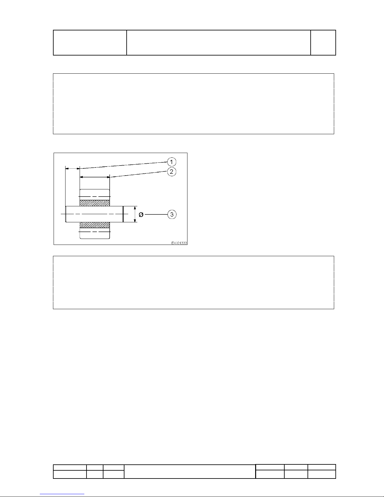
PMTAB_Picture
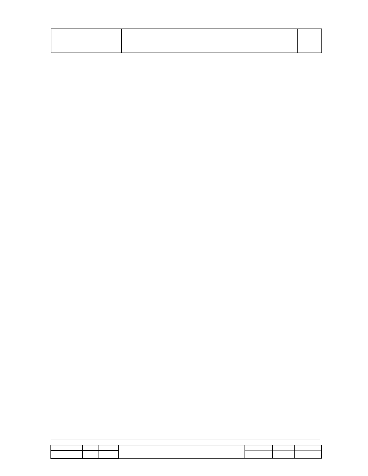
1. 116,0-116,1 mm (4.4567 - 4.4570 ")
2. Standard size: 4,00-4,03 mm (.157 - .159")
Oversize: 4,20-4,23 mm (.165 - .167")
3. Standard size: 111,50-111,52 mm
(4.389 - 4.390")
Oversize 0,5 mm: 112,00-112,02 mm
(4.409 - 4.410")
4. Max. permissible taper over length of cylinder
PMTAB_Picture
1. 115,74-115,88 mm (4.556 - 4.562")
2. Standard size 4,04-4,06 mm (.159 - .160")
Oversize: 4,24-4,26 mm (.167 - .168")
3. 108,00-108,22 mm (4.252 - 4.260")
max. wear limit: 0,1 (.039") above basic size
4. Max. permissible taper over length of cylinder
5.Standard size: 111,475-111,490 mm
(4.388 - 4.389")
Oversize: 0,5 mm (.020"): 111,975-111,990 mm
(4.408 - 4.409")
Page 11
Fav 900
Engine / Generalities
Service Data
A
General
Fav 900 chassis number 23/3001and up
13/03/2001
2000 000006
A
b
2/14
Capitel Docu-No.
Index
Date Version
Page
Service Data
Crankshaft
PM-Picturemodule
PM-Picturemodule
Text-module
PMTAB_Picture
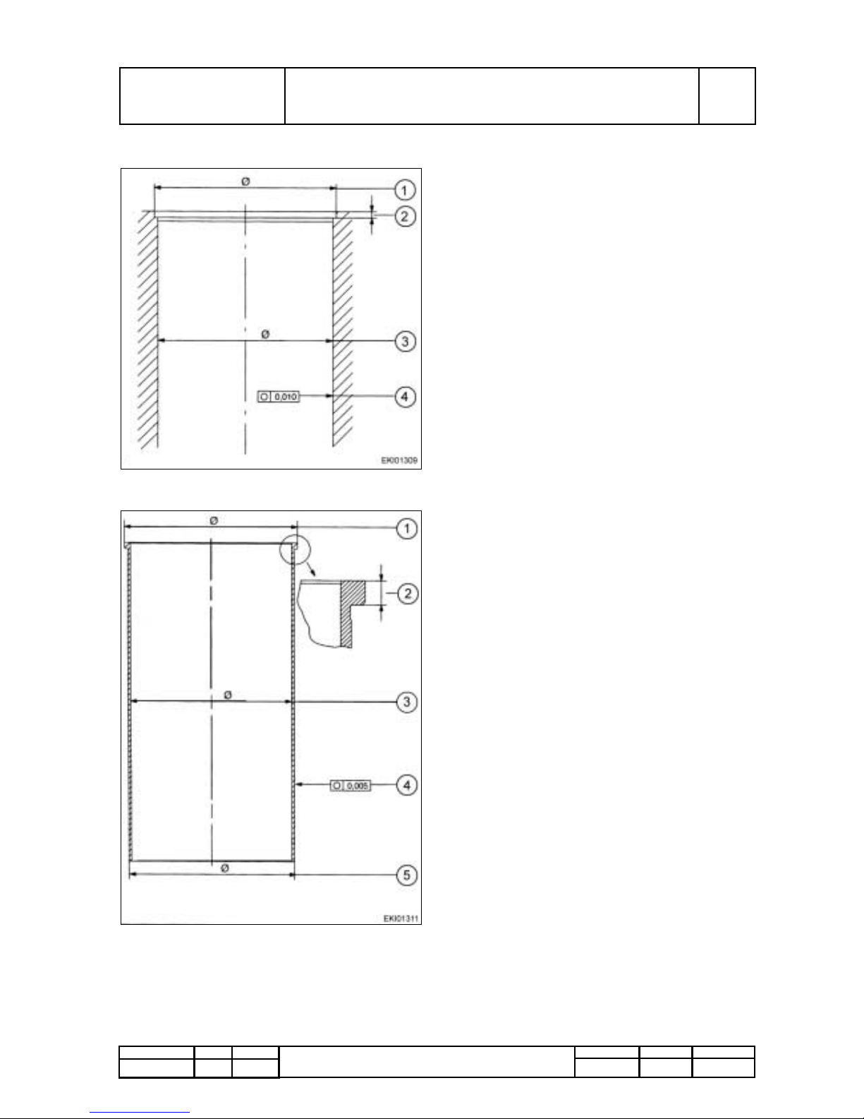
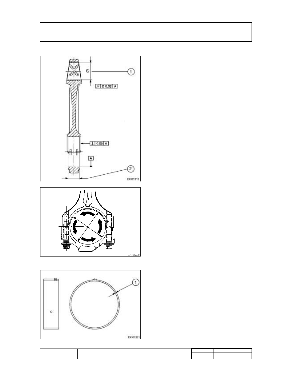
1. Dimensions:
Standard: 76,981-77,000 mm (3.031 - 3.032“)
Under size: 0,10 mm (.004"): 76,881-76,900 mm
(3.027 - 3.028")
2. Con-rod bearing journal diameter:
Standard : 69,981-70,000 mm (2.755 - 2.756")
Under size: 0,10 mm (.004"): 69,881-69,900 mm
(2.751 - 2.752")
PMTAB_Picture
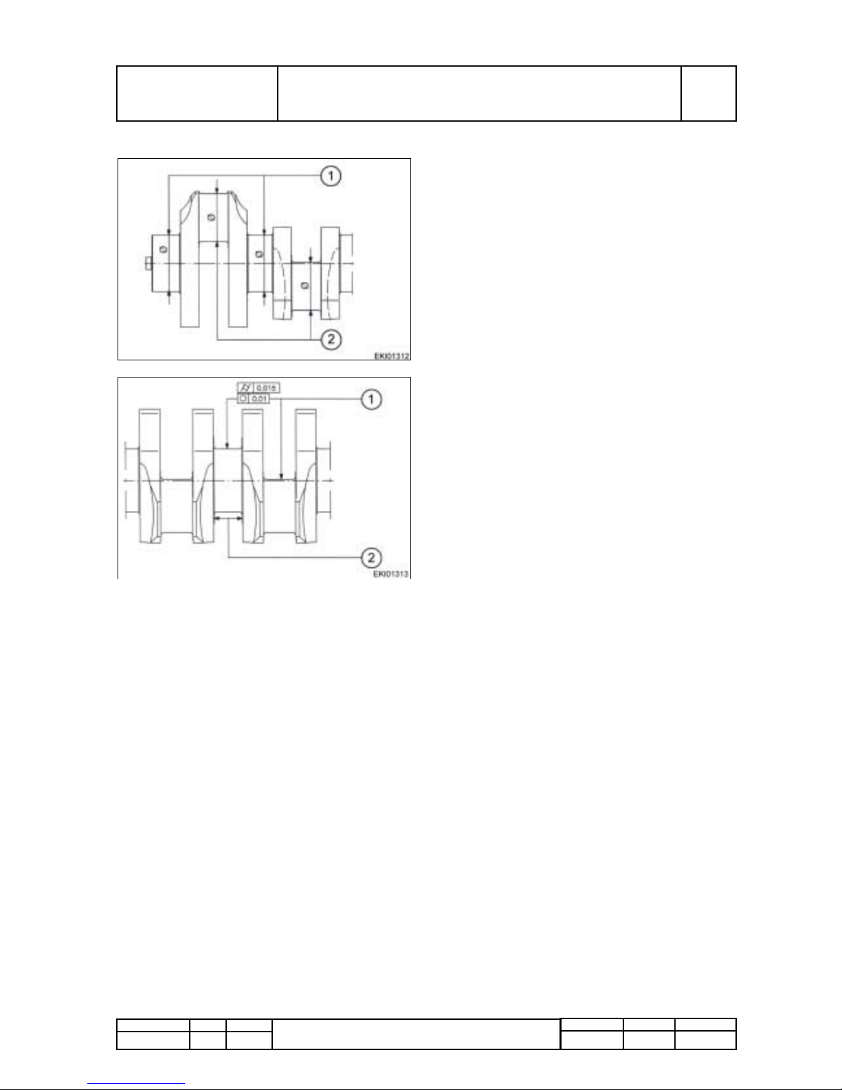
1. For all crankshaft journals:
maximal permissible runout
maximal deviation from conical form
2. Thrust bearing journal width:
Standard size: 34,000-34,062 mm
(1.339 - 1.341")
Repair sizes: 34,500-34,562 mm (1.358 - 1.361")
Page 12

Fav 900
Engine / Generalities
Service Data
A
General
Fav 900 chassis number 23/3001and up
13/03/2001
2000 000006
A
b
3/14
Capitel Docu-No.
Index
Date Version
Page
Service Data
Main bearing
PM-Picturemodule
PM-Picturemodule
Text-module
Flywheel
PM-Picturemodule
PMTAB_Picture
1. Standard size: 2,468-2,480 mm (.097 - .098")
Oversize 0,10 mm (.004"): 2,518-2,530 mm
(.099 - .100")
2. Fitted bearing inner Ø for main bearing :
Standard size : 77,040-77,086 mm
(3.033 - 3.035")
Undersize 0,10mm (.004"): 76,940-76,986 mm
(3.029 - 3.031")
Housing bore for main bearing: 82,000-82,022
mm (3.228 - 3.229")
Axial play: 0,040-0,105 mm (.002 - .004")
Spread of main spearing shells: 0,5-1,5 mm
(.020 - .059")
PMTAB_Picture
max permissible crankshaft axials play:
0,200-0,395 mm (.008 - .016")
1. Thrust bearing journal width thrust washer:
Standard size: 2,850-2,900 mm (.112 - .114")
Repair size: 3,100-3,150 mm (.122 - .124")
2. 27,967-28,000 mm (1.101 - 1.102")
PMTAB_Picture
1. Watch position of chamfer!
Fitting temperature (Shrink-on temperature):
220-240°C (428-464°F)
2. Flywheel: 352,390-352,447 mm
(13.874 - 13.876")
Ring gear (Internal): 351,671-351,760 mm
(13.845 - 13.849")
m total. = 50,3 kg (110.89 lbs.)
J total = 1,65 kgm²
3.Number of teeth : Z=125, Module 3
Mating gear (Z=11)
Backlash : 0,4-0,7 mm (.016 - .020")
Page 13
Fav 900
Engine / Generalities
Service Data
A
General
Fav 900 chassis number 23/3001and up
13/03/2001
2000 000006
A
b
4/14
Capitel Docu-No.
Index
Date Version
Page
Service Data
Text-module
Connecting rod
PM-Picturemodule
PM-Picturemodule
Text-module
Con-rod bearing
PM-Picturemodule
Text-module
PMTAB_Picture
1. 42,050-42,066 mm (1.655 - 1.656")
2. 32,78-32,88 mm (1.290 - 1.294")
Con-rod journal width: 33,0-33,1mm
(1.299 - 1.303")
PMTAB_Picture
Fit con-rod bearing caps (without shells). Measure
basic bore with an internal micrometer.
74,000-74,019 mm (2.913 - 2.914")
PMTAB_Picture
1. Standard size: 1,975-1,987 mm (.077 - .078")
Oversize 0,10 mm (.004"): 2,025-2,037 mm
(.079 - .080")
Spread of new bearing shells : 0,5-2,0 mm
(.020 - .079")
Page 14
Fav 900
Engine / Generalities
Service Data
A
General
Fav 900 chassis number 23/3001and up
13/03/2001
2000 000006
A
b
5/14
Capitel Docu-No.
Index
Date Version
Page
Service Data
Piston
PM-Picturemodule
Text-module
Piston ring grooves
PM-Picturemodule
Text-modulePiston rings
PM-Picturemodule
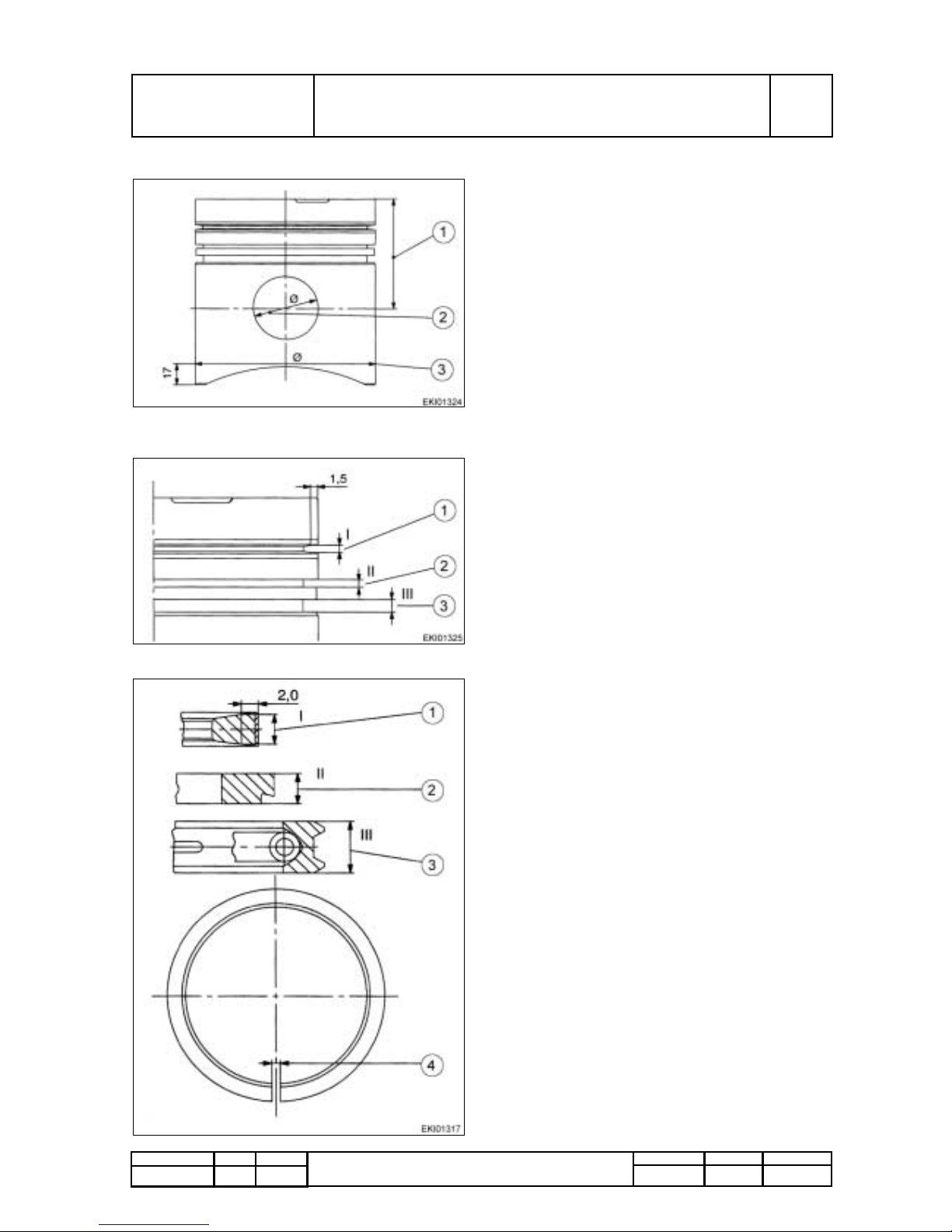
PMTAB_Picture
1. Compresion height: 63,90-64,00 mm
(2.516 - 2.519")
with undersizes 0,2 mm (.008"): 63,70-63,80 mm
(2.508 - 2.511")
with undersizes 0,4 mm (.016"): 63,50-63,60 mm
(2.500 - 2.503")
Piston projection above crankcase: 0,0093-0,391
mm (.004 - .015")
2. 42,003-42,009 mm (1.6537 - 1.6539")
Piston pin diameter: 41,994-42,000 mm
(1.6533 - 1.6535")
3. 107,891-107,900 mm (4.2477 - 4.2480")
PMTAB_Picture
1. 2,685 mm (.106")
2. 2,54-2,56 mm (.100 - .101")
3. 4,02-4,04 mm (.158 - .159")
Piston rings
PMTAB_Picture
1. Ring - keystone ring:
Height: 2,429-2,463 mm (.096 - .097")
2. Ring - chamfered ring:
Height: 2,478-2,490 mm (.097 - .098")
Axial play: 0,050-0,082 mm (.002 - .003")
3. Ring - D-ring with spring:
Height: 3,975-3,990 mm (.156 - .157")
Axial play: 0,030-0,065 mm (.001 - .002")
4. End gap clearance:
1. Ring: 0,35-0,55 mm (.001 - .002")
2. Ring: 0,3-0,5 mm (.001 - .002")
3. Ring: 0,3-0,6 mm (.001 - .002")
Page 15

Fav 900
Engine / Generalities
Service Data
A
General
Fav 900 chassis number 23/3001and up
13/03/2001
2000 000006
A
b
6/14
Capitel Docu-No.
Index
Date Version
Page
Service Data
Text-module
Cylinder head
PM-Picturemodule
PM-Picturemodule
Text-module
PMTAB_Picture
1. 10,000-10,015 mm (.3937 - .3942") at intake
and exhaust valves
2. 14,1-14,15 mm (.555 - .557")
3. 97,8-98,0 mm (3.850 - 3.860")
Minimum: 96,8 mm (3.811")
alpha = 60° Intake valve
beta = 45° Exhaust valve
PMTAB_Picture
1. Valve guide bore in cylinder head:
Standard size: 16,000-16,018 mm (.630 - .631")
Oversize: 16,250-16,268 mm (.640 - .641")
2. Valve guide outer diameter:
Standard size: 16,028-16,046 mm (.631 - .632")
Oversize: 16,278-16,296 mm (.641 - .642")
3. Standard size:
Intake valve: 10,8-10,9 mm (.425 - .429")
Exhaust valve: 11,0-11,1 mm (.433 - .437")
Oversize:
Intake valve: 11,0-11,1 mm (.433 - .437")
Exhaust valve: 11,2-11,3 mm (.441 - .445")
4. Cylinder head basic bore:
Standard size: 51,00-51,03 mm (2.008 - 2.009")
Oversize: 51,20-51,23 mm (2.016 - 2.017")
Valve seat insert outer diameter:
Standard size: 51,10-51,11 mm (2.011 - 2.012")
Oversize: 51,30-51,31 mm (2.019 - 2.020")
5.Cylinder head basic bore:
Standard size: 44,000-44,025 mm
(1.732 - 1.733")
Oversize: 44,200-44,225 mm (1.740 - 1.741")
Valve seat insert outer diameter:
Standard size: 44,10-44,11 mm (1.736 - 1.737")
Oversize: 44,30-44,31 mm (1.744 - 1.745")
Page 16

Fav 900
Engine / Generalities
Service Data
A
General
Fav 900 chassis number 23/3001and up
13/03/2001
2000 000006
A
b
7/14
Capitel Docu-No.
Index
Date Version
Page
Service Data
Valves
PM-Picturemodule
PM-Picturemodule
Text-module
PMTAB_Picture
1. Intake valve: 9,965-9,980 mm (.3923 - .3929")
Exhaust valve: 9,950-9,965 mm (.3917 - .3923")
Wear limit: max. 0,1 mm (.0039")
2. Valve recess:
Intake valve : 0,25-0,71 mm (.010 - .028")
Exhaust valve: 0,45-1,05 mm (.018 - .041")
PMTAB_Picture
Valve springs:
Untensioned approx.: 59,5-61,0 mm
(2.343 - 2.401")
Spring resistance L = 45 mm: 410-471 N
(92 - 106 lbs.)
Spring resistance L = 33,5 mm: 744-825 N
(167 - 185 lbs.)
Page 17
Fav 900
Engine / Generalities
Service Data
A
General
Fav 900 chassis number 23/3001and up
13/03/2001
2000 000006
A
b
8/14
Capitel Docu-No.
Index
Date Version
Page
Service Data
Valve operation
PM-Picturemodule
PM-Picturemodule
PM-Picturemodule
PM-Picturemodule
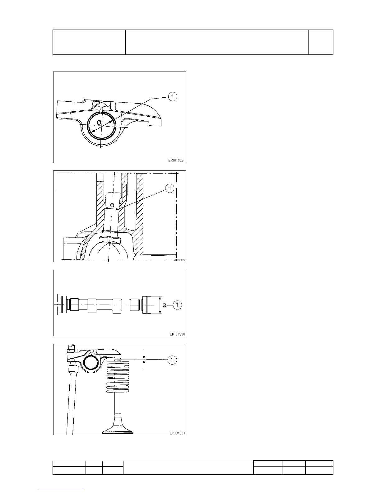
PMTAB_Picture
Rocker arm
1. 20,000-20,001 mm (.78740 - .78744")
Diameter of rocker arm bearing: 19,957-19,970
mm (.7857 - 7862")
Wear limit: 0,08 mm (.003")
PMTAB_Picture
Valve tappets
1. Tappet housing bore:
Standard size: 20,000-20,021 mm (.787 - .788")
Oversize: 20,250-20,271 mm (.797 - .798")
Tappet outer diameter:
Standard size: 19,944-19,965 mm (.785 - .786")
Oversize: 20,194-20,215 mm (.795 - .796")
PMTAB_Picture
Camshaft
Camshaft bush inner diameter: 55,07-55,14 mm
(2.168 - 2.170")
1. 1. 54,91-54,94 mm (2.162 - 2.163")
Camshaft axial diameter: 0,14-0,27 mm
(.0055 - .0106")
Wear limit: 1,5 mm (.059")
PMTAB_Picture
Valve clearance
1. Adjust when engine is cold.
Intake valve: 0,5 mm (.020")
Exhaust valve: 0,5 mm (.020")
Page 18
Fav 900
Engine / Generalities
Service Data
A
General
Fav 900 chassis number 23/3001and up
13/03/2001
2000 000006
A
b
9/14
Capitel Docu-No.
Index
Date Version
Page
Service Data
PM-Picturemodule
PM-Picturemodule
Text-module
Backlash between
Text-module
Compression pressures
Text-module
PMTAB_Picture
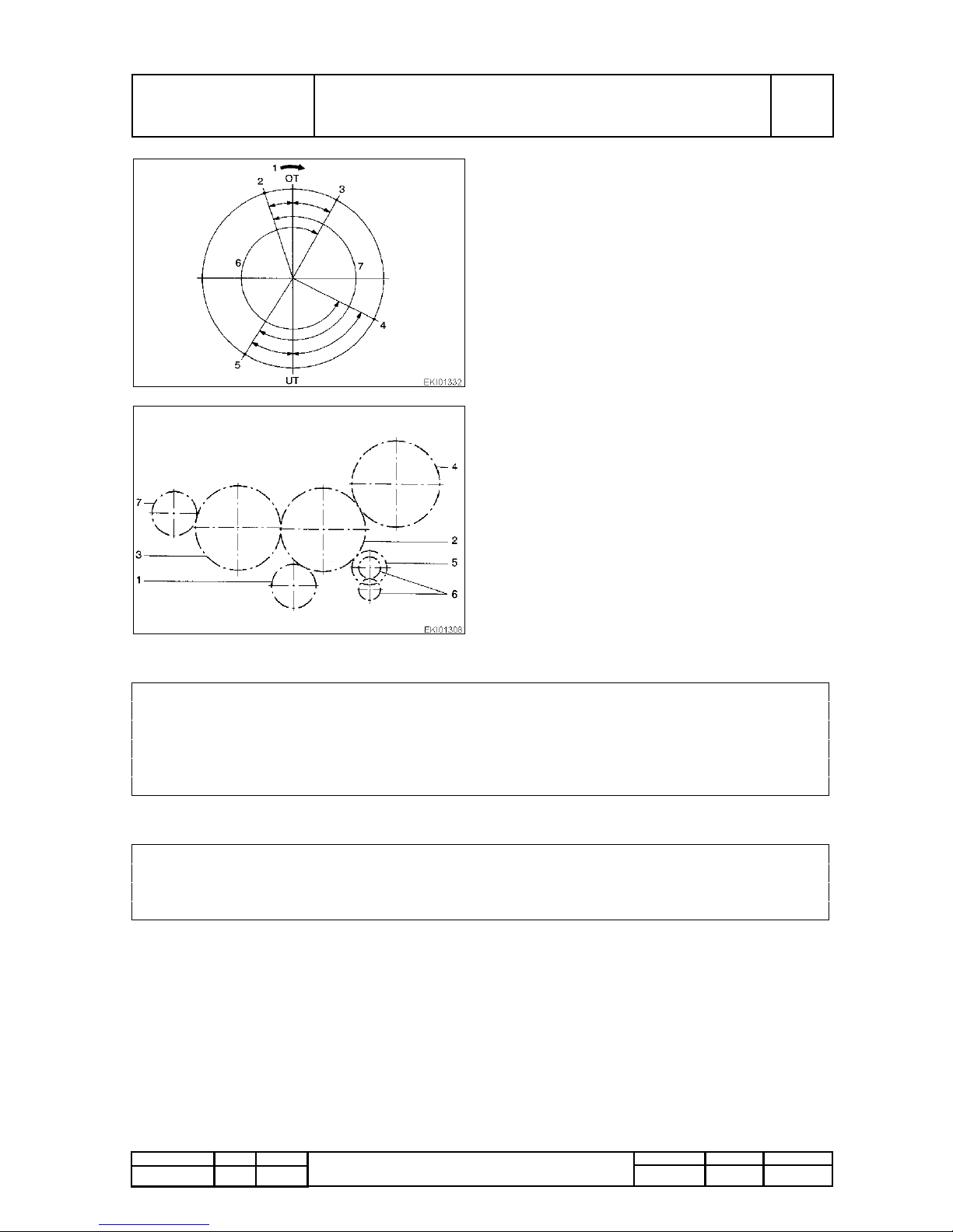
Valve timing
1. Engine direction of rotation
2. Intake valve opens 18° before TDC.
3. Exhaust valve closes 29° after TDC.
4. Exhaust valve opens 63° before TDC.
5. Intake valve closes 32° after bottom dead
point.
6. Exhaust valve opening point 272°.
7. Intake valve opening point 230°.
Figures in degrees relate to the crankshaft angle.
PMTAB_Picture
Layout of engine timing
1. Crankshaft gear
2. Intermediate timing gear
3. Camshaft gear
4. Injection pump drive gear
5. Oil pump drive gear
6. Oil pump delivery gear
7. Power take off / air compression take off
Crankshaft gear and intermediate gear 0,000-0,465 mm (0 - .018")
Intermediate gear and crankshaft gear 0,062-0,324 mm (.002 - .013")
Intermediate gear and injection pump drive 0,10-0,27 mm (.004 - .010")
Intermediate gear and oil pump drive 0,100-0,266 mm (.004 - .010")
Oil pump delivery gears 0,10-0,22 mm (.004 - .009")
Camshaft gear and hydraulic pump gear 0,10-0,15 mm (.004 - .006")
good above 30 bar (435 PSI)
permissible 27 - 30 bar (391 - 435 PSI)
needs repairing under 26 bar (377 PSI)
pressure difference max. 4 bar (58 PSI)
Page 19
Fav 900
Engine / Generalities
Service Data
A
General
Fav 900 chassis number 23/3001and up
13/03/2001
2000 000006
A
b
10/14
Capitel Docu-No.
Index
Date Version
Page
Service Data
Engine lubrication
Text-module
Oil pump
PM-Picturemodule
Text-module
Text-module
V alve opening pressures
Bypass valve for full flow oil filter 2-3 bar (29 - 44 PSI)
Oil pump pressure relief valve 5-6 bar (73 - 87 PSI)
Pressure valve of oil nozzles
Opening pressure 1,9-2,1 bar (27.5 - 30.5 PSI)
Closing pressure 1,4-1,6 bar (20.3 - 23.2 PSI)
Oil splash nozzle orifice 1,75-1,85 mm (.069 - .073")
PMTAB_Picture
Oil pump drive gear
1. 16 mm (.630")
2. D 0836 LE 501/502: 31,925-31,950 mm
(1.257 - 1.258")
D 0836 LE 503/504: 31,920-31,950 mm
(1.257 - 1.258")
Housing depth: 32,000-32,039 mm
(1.260 - 1.261")
Housing bore: 10000 N
3. Shaft: 15,94-15,95 mm (.627 - .628")
Housing bore: 16,000-16,018 mm (.630 - .631")
Oil pump delivery at pump speed (with SAE 20W/20 Oil, at 90°C (194°F) and p=6bar (87 PSI))
Gear spread 32 mm (1.260")
at n = 1008 1/min (rpm 800 1/min) 17 ltr./min (4.5 GPM)
at n = 2709 1/min (rpm 2150 1/min) 53,5 ltr./min (14 GPM)
at n = 2835 1/min (rpm 2250 1/min) 56,5 ltr./min (15 GPM)
ati n = 2961 1/min (rpm 2350 1/min) 59 ltr./min (15.5 GPM)
at n = 3087 1/min (rpm2450 1/min) 62,5ltr./min (16.5 GPM)
Page 20
Fav 900
Engine / Generalities
Service Data
A
General
Fav 900 chassis number 23/3001and up
13/03/2001
2000 000006
A
b
11/14
Capitel Docu-No.
Index
Date Version
Page
Service Data
Cooling system
PM-Picturemodule
PM-Picturemodule
Text-module
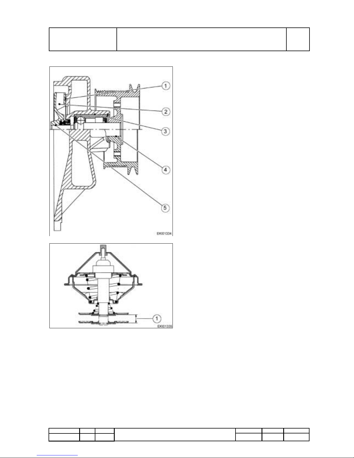
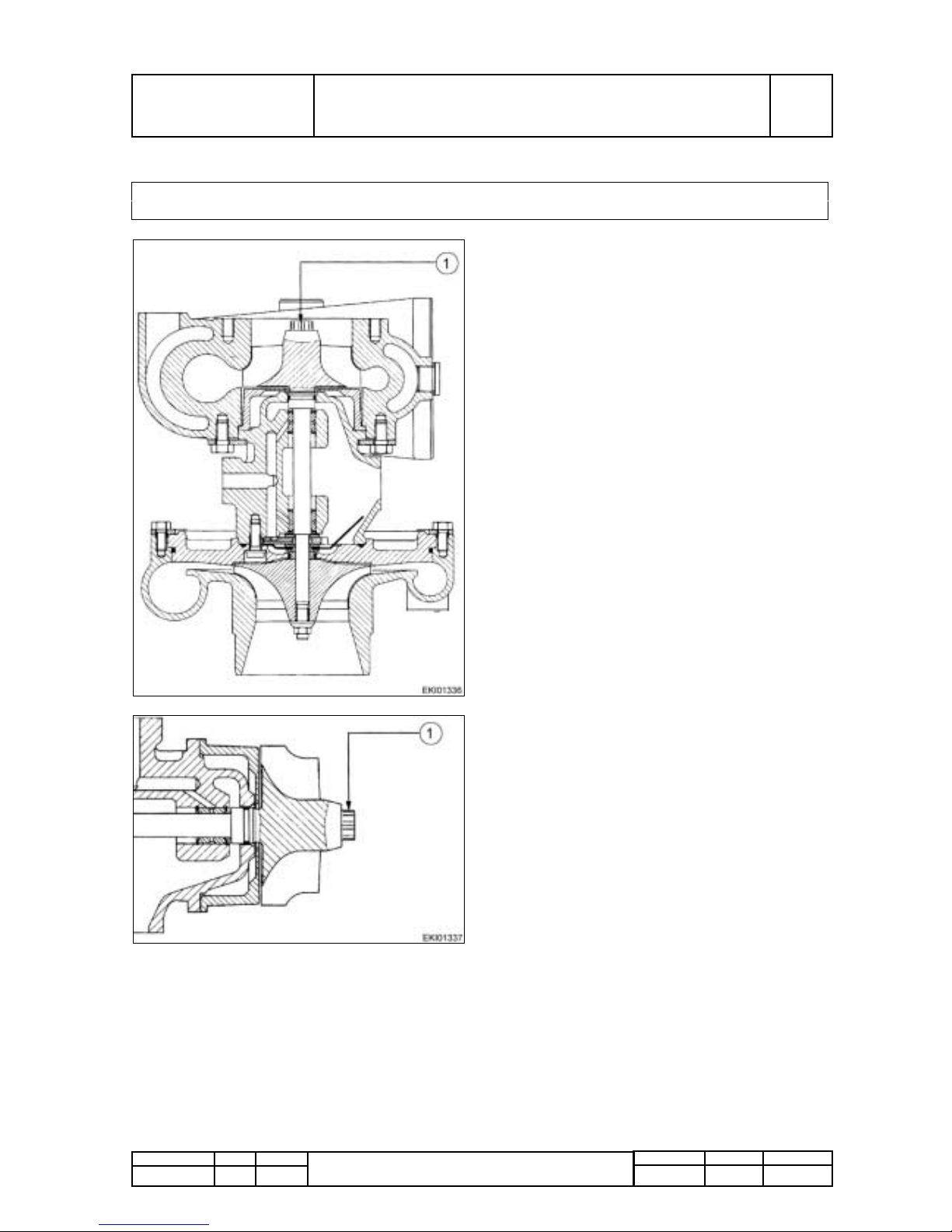
PMTAB_Picture
Water pump (engine)
1. Gap between impeller and housing:
0,5-0,9 mm (.020 - .035")
2. Impeller diameter: 136 mm (5.354")
3. Bearing location in housing:
54,940-54,970 mm (2.163 - 2.164").
Bearing diameter:
54,981-54,994 mm (2.1646 - 2.1651")
4. Bore in hub: 25,000-25,013 mm (.984 - .985").
Bearing shaft diameter: 25,048-25,061 mm
(.986 - .987").
5. Impeller bearing shaft bore: 16,000-16,018
mm (.630 - .631"). Bearing shaft diameter :
16,045-16,056 mm (.6316 - .6321).
PMTAB_Picture
Thermostat
Opening at 83°C (±2°) (181°F ±3.6°F).
Fully open: 95°C (203°F).
1. Stroke: min 8 mm at 95°C (.315" at 203°F).
Page 21
Fav 900
Engine / Generalities
Service Data
A
General
Fav 900 chassis number 23/3001and up
13/03/2001
2000 000006
A
b
12/14
Capitel Docu-No.
Index
Date Version
Page
Service Data
Turbocharger
PM-Picturemodule
PM-Picturemodule
Text-module
Manufacturer KKK
D 0836 LE 501/502/503/504 HX40-8274AW/H18W A8
PMTAB_Picture
Axial play
1. 0,038-0,093 mm (.0015 - .0037")
PMTAB_Picture
Radial play
1. 0,329-0,501 mm (.0130 - .0197")
Page 22
Fav 900
Engine / Generalities
Service Data
A
General
Fav 900 chassis number 23/3001and up
13/03/2001
2000 000006
A
b
13/14
Capitel Docu-No.
Index
Date Version
Page
Service Data
Fuel system
Injection nozzles
PM-Picturemodule
Manufacturer Bosch
Type : DSLA 154 P 625
N° of orifices 6
Nozzle opening pressure :
Nozzle holder new : 320 + 8 bar (4641 +1 16 PSI)
Nozzle holder used : 300 + 8 bar (4351 +1 16 PSI)
Nozzle injection pump with vane-cell feed pump
and automatic pressure controlled injection timer
2,68-3,47 mm (.106 - .137")
Nozzle holder KDEL 82 P 55
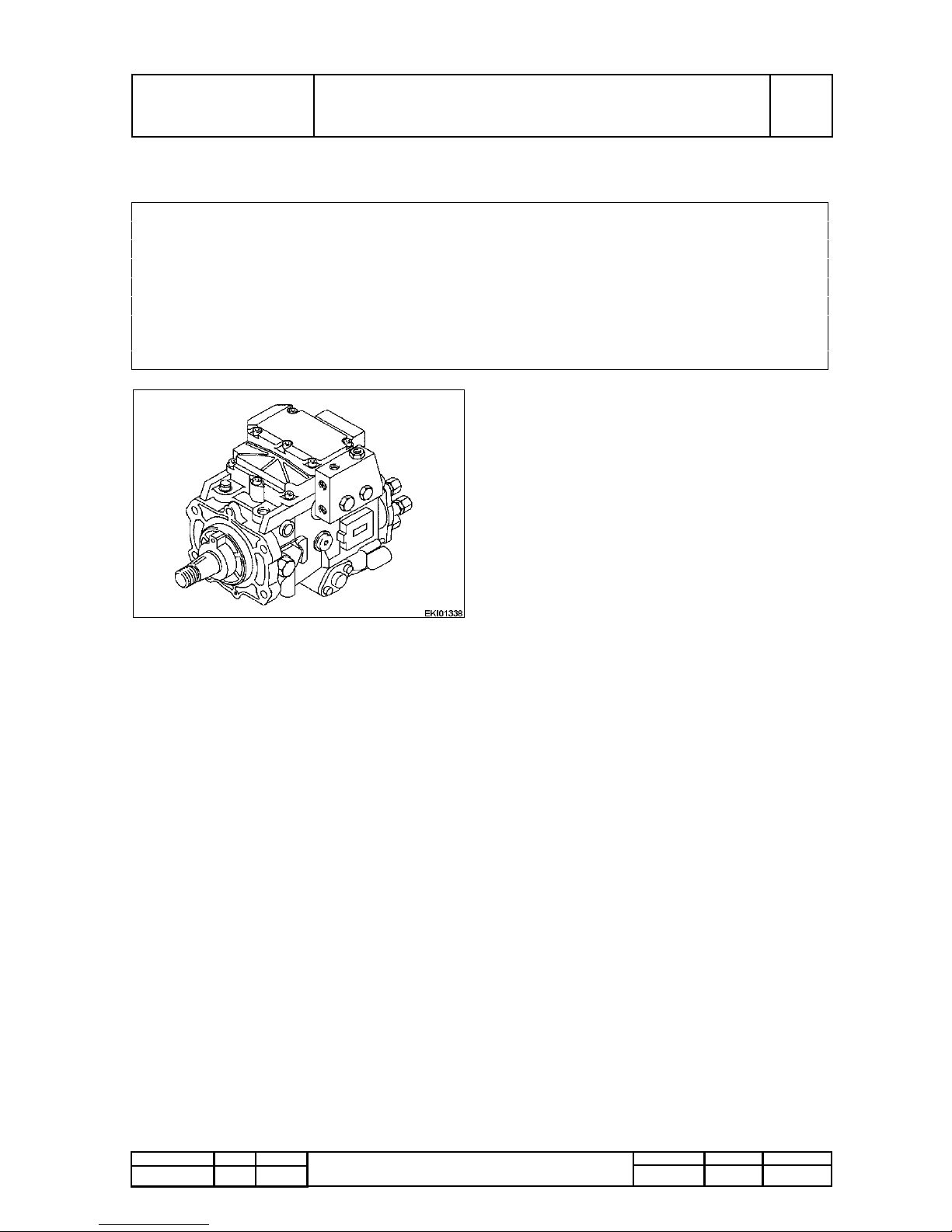
PMTAB_Picture
Injection pump
Nozzle injection pump with vane pump and
automatic pressure controlled injection timer
Manufacturer : Bosch.
Type: VP 44.
Page 23
Fav 900
Engine / Generalities
Service Data
A
General
Fav 900 chassis number 23/3001and up
13/03/2001
2000 000006
A
b
14/14
Capitel Docu-No.
Index
Date Version
Page
Service Data
PM-Picturemodule
PM-Picturemodule
Text-module
Power take-off for hydraulic pump / Air compressor
PM-Picturemodule
PMTAB_Picture
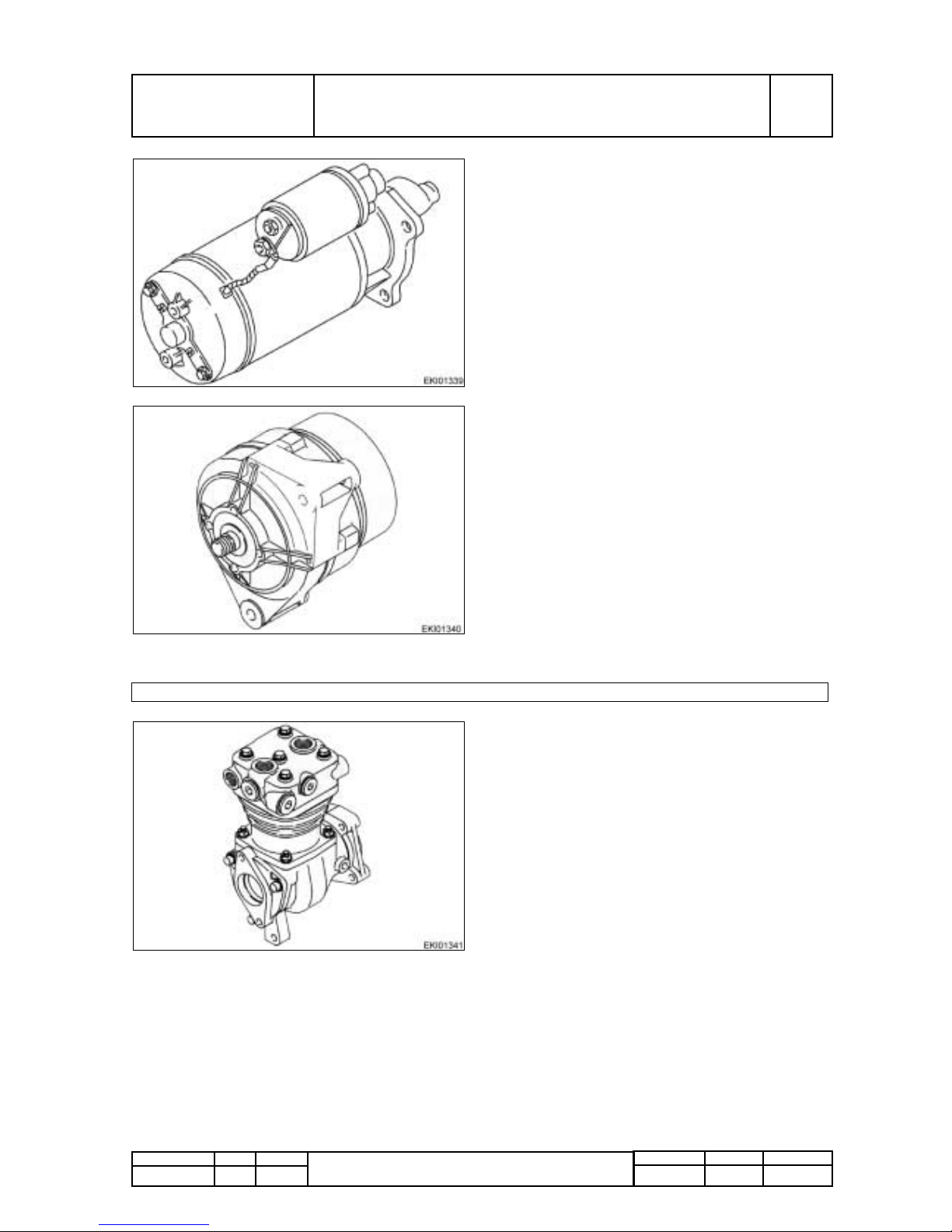
Starter
Manufacturer : Bosch
Type : EV
operationg method : pre-engaged drive
Starter pinion gear
Number of teeth: 11
Module: 3
Nominal voltage: 24 Volt
Nominal output : 4 kW (5.36 HP)
PMTAB_Picture
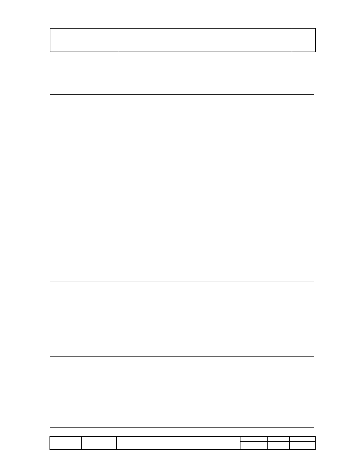
Generator
Manufactured : Bosch
Type : KC
Operating method : 3_PHASE
Nominal voltage : 14 Volt
Max. current : 45-90 Ampere
Speed 0,97 * engine speed
PMTAB_Picture
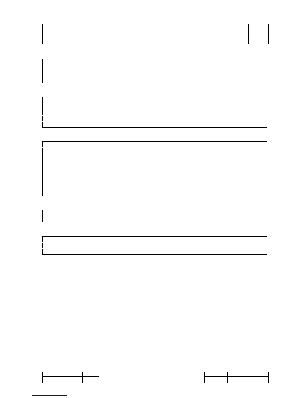
Air compressor
Single cylinder air compressor
Manufacturer: Knorr
Lubrication: Circulatory system with pressure
compression
Cooling: air-cooled
Displacement: 213 cm³ (129 in³)
Op speed: max. 3000 1/min
Op presure: max 12,5 bar (181 PSI)
Page 24
Fav 900
Engine / Generalities
Tightening Torque values
A
General
Fav 900 from chassis number 23/3001and up
13/03/2001
2000 000007
A
a
1/4
Capitel Docu-No.
Index
Date Version
Page
Tightening Torque values
Text-module
Note:
All threaded unions not specified in this table must be tightened according to our works
standard M 3059. Bolts and screws must be lightly oiled before tightening !
Plugs
Crankcase, crank gear
Cylinder head
Lubrication
DIN 908
M 14*1,5; M16*1,5 80 Nm (59,00 lbf-ft)
M 18*1,5; M22*1,5 100 Nm (73,76 lbf-ft)
M 24*1,5; M26*1,5 120 Nm (88,51 lbf-ft)
M 30*1,5 150 Nm (1 10,63 lbf-ft)
DIN 7604
AM 10*1; M12*1,5 50 Nm (36,88 lbf-ft)
AM 14*1,5 80 Nm (59,00 lbf-ft)
Crankshaft bearing cap on and crankcase
Initial torque 1 15 Nm (84,82 lbf-ft)
Angular torque 90-100°
Damper on crankshaft M14*1,5 10,9
Initial torque 150 Nm (1 10,63 lbf-ft)
Angular torque 90-100°
Damper on crankshaft M14*1,5 12,9
Initial torque 150 Nm (1 10,63 lbf-ft)
Angular torque 90-100°
Angular torque 90-100°
Flywheel on crankshaft
Initial torque 100 Nm (73,76 lbf-ft)
Angular torque 90-100°
Con-rod bearing caps
Initial torque 50-60 Nm (36,88-44,25 lbf-ft)
Angular torque 90-100°
For tightening and retightening of cylinder head bolts see following page
Lock nut for valve adjusting screw 40 Nm (29,50 lbf-ft)
Cheese-head screws with hexagonal socket for bolts of interme-
diate gear
1 15 Nm (84,82 lbf-ft)
Collar screw for crankshaft 65 Nm (47,94 lbf-ft)
Rocker socket (T orx E12) 65 Nm (47,94lbf-ft)
Oil pressure valve for piston spray nozzle 38-42 Nm (28,03-30,98 lbf-ft)
Oil pump drive gear on shaft 30 Nm (22,13 lbf-ft)
Screw plug for pressure relief valve in crankcase 60Nm (44,25 lbf-ft)
Oil pan drain plug 60Nm (44,25 lbf-ft)
Screw plug for oil filter head (M 10*1) 20 Nm (14,75 lbf-ft)
Threaded coupling for oil filter 40 Nm (29,50 lbf-ft)
Screw plug in oil filter (M 18*1,5) 30 Nm (22,13 lbf-ft)
Screw plug in oil filter (M 24*1,5) 30 Nm (22,13 lbf-ft)
Screw plug in oil filter (M 30*1,5) 40 Nm (29,50 lbf-ft)
OIl change filter 25 Nm (18,44 lbf-ft)
Page 25
Fav 900
Engine / Generalities
Tightening Torque values
A
General
Fav 900 from chassis number 23/3001and up
13/03/2001
2000 000007
A
a
2/4
Capitel Docu-No.
Index
Date Version
Page
Tightening Torque values
Cooling system
Exhaust / Intake manifolds
Fuel system
Starter / Alternator /Compressor
Sensors
Screw plug in coolant pipe (M14*1,5) 20 Nm (14,75 lbf-ft)
Hose clips :
Clamping range 12 to 31 mm, 9 mm wide 3,6 Nm (2,66 lbf-ft)
over 32 mm, 13 mm wide 5 Nm (3,69 lbf-ft)
Exhaust manifold on cylinder head
Initial torque 50-55 Nm (36,88-40,75 lbf-ft)
Angular torque 90-100°
Banjo bolt of solenoid valve 10-15 Nm (7,38-1 1,06 lbf-ft)
Knuckle pin clap of turbocharger 12 Nm (8,85 lbf-ft)
Nozzle holder in cylinder head 70 Nm (51,63 lbf-ft)
Nozzle adjusting nut 45 Nm (33,19 lbf-ft)
Banjo bolt for leak oil 10-12 Nm (7,38-8,86 lbf-ft)
Pressure line at nozzle
Initial torque 10 Nm (7,38 lbf-ft)
Angular torque 60°
Banjo bolt on oil filter 20-30 Nm (14,75-22,13 lbf-ft)
Fuel filter 10-15 Nm (7,38-1 1,06 lbf-ft)
Purge plug on fuel filter 8-10 Nm (5,90-7,38 lbf-ft)
Alternator pulley 75-85 Nm (55,32-62,69 lbf-ft)
Compressor drive gear 200-250 Nm (147,51-184,39 lbf-ft)
Oil pressure sensor 80 Nm (59,00 lbf-ft)
T emperature sensor switch 15 Nm (11,06 lbf-ft)
Coolant T emperature sensor (EDC) 35 Nm (25,82 lbf-ft)
Page 26
Fav 900
Engine / Generalities
Tightening Torque values
A
General
Fav 900 from chassis number 23/3001and up
13/03/2001
2000 000007
A
a
3/4
Capitel Docu-No.
Index
Date Version
Page
Tightening Torque values
Assembly tightening torques to works standard M 3059
External or internal hexagon nuts and bolts, heads without collar or flange.
Tread size * Pitch Property class / Tightening torque in Nm (lbf-ft)
at 8,8/8 at 10,9/10 at 12,9/12
M4 2,5 (1,84) 4,0 (2,95) 4,5 (3,32)
M5 5,0 (3,69) 7,5 (5,53) 9,0 (6,64)
M6 9,0 (6,64) 13,0 (9,59) 15,0 (1 1,06)
M7 14,0 (10,33) 20,0 (14,75) 25,0 (18,44)
M8 22,0 (16,23) 30,0 (22,13) 35,0 (25,81)
M8*1 23,0 (16,96) 35,0 (25,81) 40,0 (29,50)
M10 45,0 (33,19) 65,0 (47,94) 75,0 (55,32)
M10*1,25 45,0 (33,19) 65,0 (47,94) 75,0 (55,32)
M10*1 50,0 (36,88) 70,0 (51,63) 85,0 (62,62)
M12 75,0 (55,32) 105,0 (77,44) 125,0 (92,20)
M12*1,5 75,0 (55,32) 1 10,0 (81,13) 130,0 (95,88)
M12*1,25 80,0 (59,00) 1 15,0 (84,20) 135,0 (99,57)
M14 1 15,0 (84,20) 170,0 (125,39) 200,0 (147,51)
M14*1,5 125,0 (92,20) 185,0 (136,45) 215,0 (158,58)
M16 180,0 (132,76) 260,0 (191,77) 310,0 (228,64)
M16*1,5 190,0 (140,14) 280,0 (206,52) 330,0 (243,40)
M18 260,0 (191,77) 370,0 (272,90) 430,0 (317,15)
M18*2 270,0 (199,14) 290,0 (213,89) 450,0 (331,90)
M18*1,5 290,0 (213,89) 410,0 (302,40) 480,0 (354,03)
M20 360,0 (265,52) 520,0 (383,53) 600,0 (442,54)
M20*2 380,0 (280,27) 540,0 (398,28) 630,0 (464,66)
M20*1,5 400,0 (295,02) 570,0 (420,41) 670,0 (494,17)
M22 490,0 (361,40) 700,0 (516,29) 820,0 (604,80)
M22*2 510,0 (376,16) 730,0 (538,42) 860,0 (634,30)
M22*1,5 540,0 (398,28) 770,0 (567,92) 900,0 (663,80)
M24 620,0 (457,29) 890,0 (656,43) 1040,0 (767,06)
M24*2 680,0 (501,54) 960,0 (708,06) 1130,0 (833,44)
M24*1,5 740,0 (545,8) 1030,0 (759,69) 1220,0 (899,82)
Page 27
Fav 900
Engine / Generalities
Tightening Torque values
A
General
Fav 900 from chassis number 23/3001and up
13/03/2001
2000 000007
A
a
4/4
Capitel Docu-No.
Index
Date Version
Page
Tightening Torque values
Cylinder head bolts
Tightening cylinder head bolts following repair work (new engine)
Only for Torx-head screws.
No tightening for Torx-head screws.
Tightening cylinder head bolts following repair work
(cold engine)
Only for Torx-head screws.
PM-Picturemodule
PM-Picturemodule
Text-module
Tightening cylinder head bolts following repair work
Only for Torx-heads.
No tightening for Torx-head screws.
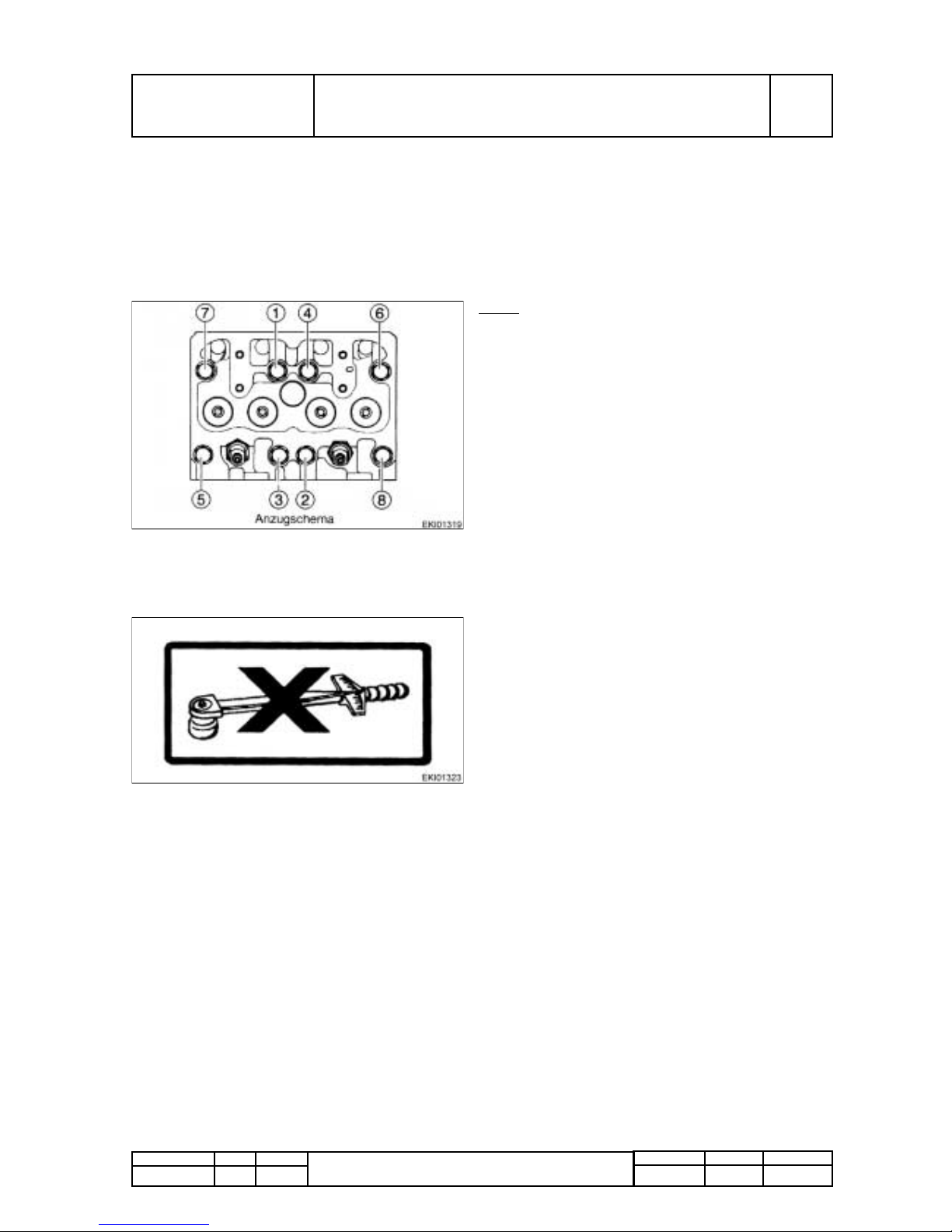
PMTAB_Picture
Note:
Only use new cylinder head bolts. do not re use.
before inserting bolts, lubricate threads (not the
tapped bores) and the bolt heads with "Optimoly
White T" paste. Do not use oils or additives
containing MoS
2
-h. Tighten bolts by the torque
angle method following the diagram :
● 1.st initial stage = 10 Nm (7,38 lbf-ft).
● 2.nd initial stage = 80 Nm (59,00 lbf-ft).
● 3.rd initial stage = 150 Nm (110,63 lbf-ft).
● 4.tth initial stage = 90°.
● 5.th initial stage = 90°.
● Final stage = 90°.
Adjust valve play
PMTAB_Picture
Put on sticker number 51.97801-0150.
Page 28

Fav 900
Engine / General system
Turbocharger, troubleshooting
B
Faults
Fav 900 chassis number 23/3001 and up
15.2.2001
2000 000003
B
a
1/2
Capitel Docu-No.
Index
Date Version
Page
Turbocharger, troubleshooting
Text-module
Before replacing the turbocharger, check the following:
Excessive engine oil consumption, lack of power and abnormal intake or exhaust noises are a frequent
cause of unnecessary turbocharger replacement.
Examination of the allegedly defective parts by the manufacturer often shows the turbocharger to be in
perfectly good working order.
To avoid this situation, the following checks must be performed :
Text-module
Excessive oil consumption
Bullet-List
● Check air filter contamination
● Check intake pipe for restricted cross section (e.g. damage, dirt)
Either are possible causes for increased oil consumption due to the higher pressure.
Bullet-ist
● Check turbocharger for external traces of oil
Excessive oil consumption of the turbocharger is due to bearing wear, quickly resulting in mechanical
damage.
Text-module
Lack of power
For satisfactory power, observe correct settings for:
Bullet-
● start of fuel delivery
● valves clearance
● engine control (at full load)
● exhaust brake (must open fully).
Bullet-List
Also check:
● Cylinder compression
● air filter contamination
● intake system for restricted cross sections and leaks
● exhaust system for damage and leaks.
If none of these checks reveal the cause of poor performance, the turbocharger has to be also checked
for:
Bullet-List
● Coking of turbine impedes easy rotation. (Axial movement may realese coking.)
● Dirt within compressor
● Damage by foreign objects
● Turbine wheel in contact with housing
Remove visible contamination of compresssor side and check bearing clearance.
Text-module
Note:
Do not damage the compressor fan wheel.
Bullet-List
Abnormal intake and exhaust noises
● Check intake and exhaust system adjacent to the turbocharger assembly. Damaged gaskets must
be replaced (can mislead to failure diagnostic of turbocharger).
● If this does not eliminate the abnormal noises, the turbocharger is to be replaced. (A turbocharger in
good condition does not generate noise!)
Text-module
Page 29
Fav 900
Engine / General system
Turbocharger, troubleshooting
B
Faults
Fav 900 chassis number 23/3001 and up
15.2.2001
2000 000003
B
a
2/2
Capitel Docu-No.
Index
Date Version
Page
Turbocharger, troubleshooting
Oil in intake pipes and intercooler
Oilspray within the intake system is necessary. It lubricates inlet valve seats.
If too much oil is encountered to such an extent that puddles can be found within the air box of the
intercooler, there is a serious risk of engine "runaway", an uncontrolled increase of engine speed .
Leaks must immediately be removed.
Possible origins:
Bullet-List
● Engine oil level too high - Check whether proper dipstick is used -
● Inadequate engine oil, check "Lubricants " schedule.
● Operation on not allowed high slanting angles
● High pressure within crankcase, e. g. Oil release valve failure (Crank case venting) or worn piston
rings
Text-module
Turbocharger compressor coking
Can occur by excessive intake air temperature, e.g. during constant full load opreation.
Coking may result in reduced intake air pressure, there will not be a noticeable power reduction or a
diminished acceleration behavior. Coking may result in exhaust turbitidy.
If Turbocharger compressor coking occurs:
Bullet-List
● Disassemble compressor housing. Avoid compressor fan wheel damage which could result in
balancing problems and strong vibrations until complete destruction of the turbocharger.
● Use a solvent to remove coking from the compressor housing
Bullet-List
● In severe cases, use special oil with low coking risk.
Warning:
Never inject solvent spray while the engine is running - Accident Hazard !!! -
Page 30
Fav 900
Engine / Generalities
View of engine D 0836 LE 501
D
Component Location
Fav 900 chassis number 23/3001and up
09/03/2001
2000 000003
D
a
1/1
Capitel Docu-No.
Index
Date Version
Page
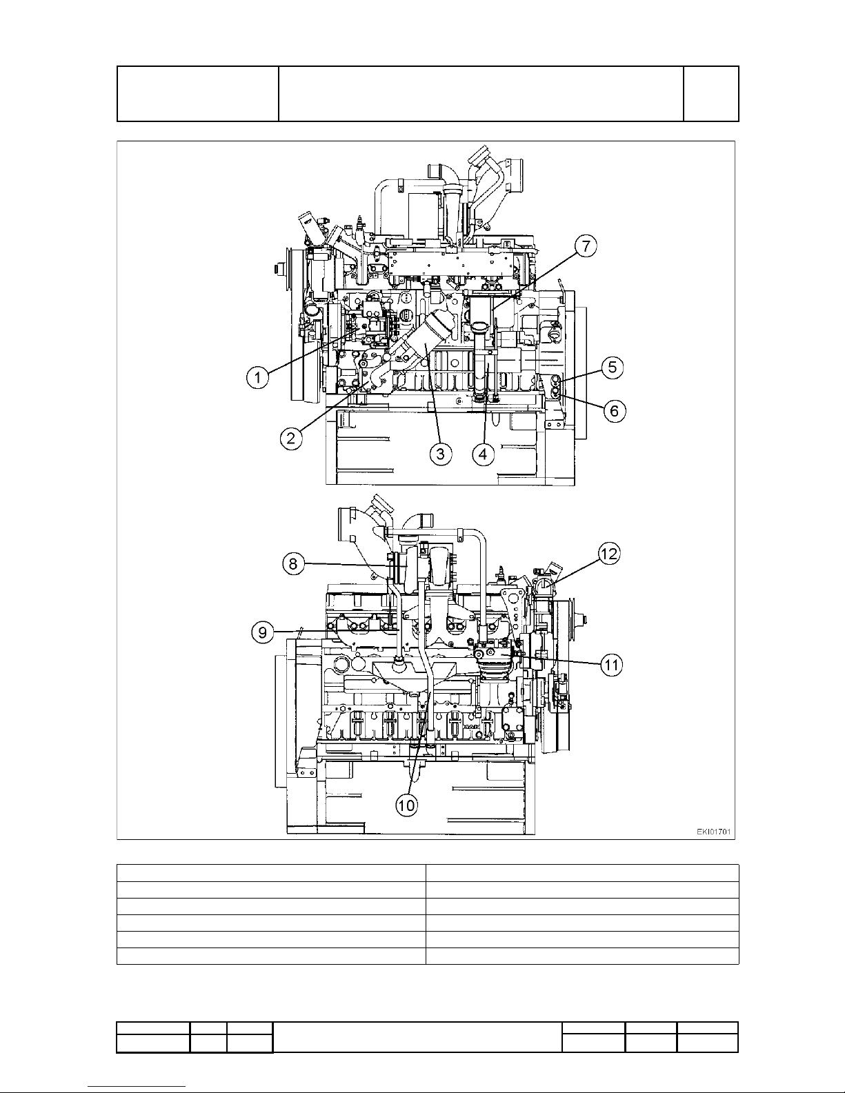
View of engine D 0836 LE 501
PM-Picturemodule
Text-module
PMTAB_Picture
1 Fuel injection pump (VP44) 7 Fuel filters
2 Lubricant cooler 8 Turbocharger
3 Lubricant filter 9 Lubrication oil turbocharger (pressure)
4 Oil filling socket, Oil level indicator 10 Lubrication oil return from turbocharger
5 B10 - Sensor , Engine 1 11 Air compressor
6 B1 1 - Sensor , Engine 2 12 Thermostat
Page 31

Fav 900
Engine / Cylinder head
Checking compression
E
Testing
Fav 900 chassis number 23/3001and up
20.2.2001
2010 000001
E
a
1/1
Capitel Docu-No.
Index
Date Version
Page
Checking compression
PM-Picturemodule
PM-Picturemodule
PM-Picturemodule
PM-Picturemodule
PMTAB_Picture
● Warm up engine until coolant temperature
reaches 60 to 80°C (140 - 176°F).
● Check valves clearance and adjust.
● Remove all injectors and injector holders.
● See values of compression in chapter "Service
Data".
Starting with the 1st cylinder, fit new seal and
tighten. Install test adaptor of compression
recorder with threaded union and tighten.
PMTAB_Picture
Screw compression recorder onto test adaptor
and insert test sheet.
Using the starter motor, turn engine until the
indicator no longer deflects.
Connect compression recorder with test adapter
to the other cylinders and proceed as above.
PMTAB_Picture
Depending on the design of the compression
recorder, the engine can also be cranked directly
from the compression recorder.
To do this, the starter has to be connected to the
appropriate electrical leads.
PMTAB_Picture
Compare data and remove compression recorder
and test adapter. Apply "Never Seeze" to contact
faces of injector holders.
Fit injector holder and injectors using a new seal.
Screw on union nut and tighten to specified
torque.
Re-connect injection and leak-oil lines.
Note:
The union nut can be tightened with an open
end wrench without removing the injection
pipe.
Page 32

Fav 900
Engine / Cylinder head
Checking valve timing
F
Setting and Calibration
Fav 900 chassis number 23/3001and up
20.2.2001
2010 000002
F
a
1/1
Capitel Docu-No.
Index
Date Version
Page
Checking valve timing
Text-module
Checking valve timing
Shifting of the camshaft drive gear can result in severe engine damage.
It is therefore necessary to ensure a correct fit by checking the valve timing after repair.
The above takes into consideration that tappet push rods are not distorted!
Proceed as follows:
Bullet-List
● Fit engine actuation device to flywheel housing.
● Remove crankcase venting pipe.
● Accurately set valve play of 1st cylinder.
● Actuate engine against rotating direction to approx. 40°C before TDP.
● Set dial gauge onto intake valve spring retainer of 1st cylinder and set at "0".
● Slowly turn crankshaft in rotating direction and watch the pointer:
● Immediatey when the pointer moves, the intake valve opens.
● Take reading from graded scale on flywheel and compare with valve timing.
Note:
By fitting a dial gauge to both intake and exhaust valve spring retainers of the 1st cylinder, it is
possible to check all valve timings and the valve stroke by continued turning of the engine. V alve
stroke desired value: 5,0 to 5,7 mm (.197 - .224").
Page 33

Fav 900
Engine / Cylinder head
Setting valve clearance
F
Setting and Calibration
Fav 900 chassis number 23/3001 and up
15.2.2001
2010 000003
F
a
1/2
Capitel Docu-No.
Index
Date Version
Page
Setting valve clearance
PM-Picturemodule
PM-Picturemodule
Text-module
Setting valves clearance:
Valves overlap on cylinder:
PM-Picturemodule
PMTAB_Picture
Engine must be cold for adjusting valve clearance.
(max. coolant temperature 50° C (122°F))
Setting valve clearance.
PMTAB_Picture
Rotate crankshaft using turning device until the
piston of the cylinder to be set is at top dead
centre ( TDC ) and the rocker arms are not loaded.
The valves of the synchronous cylinder are now
overlapping.
153624
624153
PMTAB_Picture
Layout of cylinder sequence and position of valves
I Fan end
II Flywheel end
A Exhaust valve
E Intake valve
Page 34

Fav 900
Engine / Cylinder head
Setting valve clearance
F
Setting and Calibration
Fav 900 chassis number 23/3001 and up
15.2.2001
2010 000003
F
a
2/2
Capitel Docu-No.
Index
Date Version
Page
Setting valve clearance
PM-Picturemodule
PMTAB_Picture
● Insert gauge between valve shaft and rocker .
● With valve setting tool loosen lock nut and turn
setting screw until gauge can be moved with a
slight resistance.
● Tighten lock nut.
● Check clerance again.
● Refit cylinder head covers.
● Tighten screws and bolts to adequate torque.
Page 35

Fav 900
Engine / Cylinder head
Reassembling and refitting intake pipe
G
Repair
Fav 900 chassis number 23/3001 and up
15.2.2001
2010 000002
G
a
1/1
Capitel Docu-No.
Index
Date Version
Page
Reassembling and refitting intake pipe
PM-Picturemodule
PM-Picturemodule
PM-Picturemodule
PMTAB_Picture
Removing intake pipe
Note:
T o avoid engine damage, always ensure clean
conditions when working on intake system.
● Disconnect pressure sensor for intercooler
● Disconnect wiring to flame booster plug, to
solenoid switch ant to the temperature sensors.
● Remove fuel lines to flame booster plug and to
solenoid valve.
● Remove wiring harness.
● Remove fuel filter.
● Remove fuel pre filter with manual lifting pump
● Remove collars of the injection lines and of the
fuel lines wich are fitted onto the intake
manifold.
PMTAB_Picture
Loose and remove intake pipe fixing bolts on the
cylinder head.
Detach intake pipe, remove traces of gasket
residue from sealing faces of intake pipe and
cylinder head.
Note:
Do not allow dirt particles to enter the inlet
ports.
PMTAB_Picture
Refitting intake pipe
Position intake pipe using new gaskets.
Insert fixing bolts.
Watch proper positionning of the gasket.
Tighten to specified torque.
replace all parts wich have been removed before
Purge fuel system.
Page 36

Fav 900
Engine / Cylinder head
Removing and refitting turbocharger
G
Repair
Fav 900 chassis number 23/3001 and up
15.02.2001
2010 000004
G
a
1/2
Capitel Docu-No.
Index
Date Version
Page
Removing and refitting turbocharger
PM-Picturemodule
PM-Picturemodule
PM-Picturemodule
PM-Picturemodule
PMTAB_Picture
Removing turbocharger
Remove crankcase venting (pressure control
valve).
Remove air intake pipe from compressor to intake
manifold.
Remove air intake manifold.
PMTAB_Picture
Remove oil return line and feed line.
PMTAB_Picture
Remove heat protection panel
PMTAB_Picture
Unscrew the turbocharger.
Remove turbocharger.
Note:
Shut all inlet and outlet ports in order to
prevent particle contamination.
Page 37

Fav 900
Engine / Cylinder head
Removing and refitting turbocharger
G
Repair
Fav 900 chassis number 23/3001 and up
15.02.2001
2010 000004
G
a
2/2
Capitel Docu-No.
Index
Date Version
Page
Removing and refitting turbocharger
PM-Picturemodule
PM-Picturemodule
PMTAB_Picture
Refitting the turbocharger
Check intake pipe and exhaust manifold for
eventual foreign objects.
Examine oil feed and return lines for eventual
damage, jamming and leaks.
Replace all gaskets.
Refitting the turbocharger occurs in the inversed
sequence as the removing
For refitting use new gaskets and new locking
nuts.
Before connecting oil feed line, fill bearing case
with clean engine oil.
Check all connection fot tightness and absence of
mecanical stress.
PMTAB_Picture
Note:
The clamped section of the hose must always
be behind the collar of the hose.
1. Pipe
2. Gap
3. Hose
4. Collar
5. Hose clip
Note:
Use only clean water as a lubricant.
Page 38

Fav 900
Engine / Cylinder head
Removing and refitting exhaust manifold
G
Repair
Fav 900 Chassis number 23/3001 and up
15.02.2001
2010 000003
G
a
1/1
Capitel Docu-No.
Index
Date Version
Page
Removing and refitting exhaust manifold
PM-Picturemodule
PM-Picturemodule
PM-Picturemodule
PM-Picturemodule
PMTAB_Picture
Removing the exhaust manifold
Remove turbocharger.
Note:
Protect exhaust port on turbocharger from
contamination.
Unscrew and remove nuts from exhaust manifold.
PMTAB_Picture
Guidance pins (visible on photograph) may be
used.
Remove manifold.
PMTAB_Picture
Refitting the exhaust manifold
Clean sealing faces of both, cylinder head and
manifold.
Bumped side (1) of gasket facing the cylinderhead
(2), depression facing the manifold (3).
PMTAB_Picture
Insert screws and tighten to adequate torque.
Refit the turbocharger.
Page 39

Fav 900
Engine / Cylinder head
Removing and refitting cylinder head
G
Repair
Fav 900 chassis number 23/3001 and up
16.02.2001
2010 000006
G
a
1/4
Capitel Docu-No.
Index
Date Version
Page
Removing and refitting cylinder head
PM-Picturemodule
PM-Picturemodule
PM-Picturemodule
PM-Picturemodule
PMTAB_Picture
Removing the rocker
Remove cylinder head cover.
PMTAB_Picture
Loosen clamping bolts and remove rocker arm.
Dismantling, overhauling and reassembling rocker
assembly.
Removing the cylinder head
● Drain coolant,
● remove lines from injection nozzles,
● Remove intake pipe,
● Remove exhaust manifold,
● Remove coolant pipe.
PMTAB_Picture
Remove push rods.
PMTAB_Picture
Loosen cylinder head bolts in reverse sequence of
tightening (for tightening torque values refer to
chap 2000 Reg A).
Note:
Cylinder head bolts must not be re-used.
Remove cylinder head and lay down in such way
to prevent damage.
Remove cylinder head gasket.
Page 40

Fav 900
Engine / Cylinder head
Removing and refitting cylinder head
G
Repair
Fav 900 chassis number 23/3001 and up
16.02.2001
2010 000006
G
a
2/4
Capitel Docu-No.
Index
Date Version
Page
Removing and refitting cylinder head
PM-Picturemodule
PM-Picturemodule
PM-Picturemodule
PMTAB_Picture
Before refitting the cylinder head :
● Clean all the parts which have been removed.
● Clean sealing faces of cylinder head and
crankcase, and blow out tapped holes in
crankcase.
● In the event of repeated leaking, use the
straight edge to chek the sealing faces of
cranskcase and cylinder head for distortion.
● Uneven cylinder heads can be surface ground
by up to 1 mm.
● Remachined sealing surfaces are measured in
relation to the bore centre of the cranskshaft
bearing.
Note:
Sealing surface of the cylinder head and
crankcase may only be cleaned manually by
scraper and slight sandpaper on a polishing
block.
PMTAB_Picture
Insert two 6h 8x10 DIN 7 straight pins per head
into the leading surface of the crankshaft housing
to locate the cylinder heads
PMTAB_Picture
If these straight pins need replacing, observe the
max. projection of 4,5mm.
Page 41

Fav 900
Engine / Cylinder head
Removing and refitting cylinder head
G
Repair
Fav 900 chassis number 23/3001 and up
16.02.2001
2010 000006
G
a
3/4
Capitel Docu-No.
Index
Date Version
Page
Removing and refitting cylinder head
PM-Picturemodule
PM-Picturemodule
PM-Picturemodule
PM-Picturemodule
PMTAB_Picture
Refitting the cylinder head
Note:
Cylinder head gasket must always be replaced.
Install a dry new gasket carefully positioned
according to the hole pattern . Fit cylinder head.
PMTAB_Picture
Note:
To prevent distortion between cylinder heads
and manifolds, we recommend the following
steps :
● Refit cylinder heads using guidance bolts.
● Oil the new cylinder head bolts and their rest
surface with "Optimoly Withe T" paste.
● Hand tighten new cylinder head bolts.
● Mount rectified ruler (Special tool) onto the
exhaust side. Tighten screws at 20 Nm. If no
ruler is available, fit exhaust pipe and tighten at
20 Nm.
PMTAB_Picture
● Tighten progressively cylinder head bolts in the
indicated sequence at the prescribed torque.
● Remove the rectified ruler.
PMTAB_Picture
Refitting the rocker assembly
Check push rods for distortion and wear in the ball
sockets.
When inserting the push rods ensure correct fit in
the socket of the valve tappets.
Fit rocker arm bracket.
Page 42

Fav 900
Engine / Cylinder head
Removing and refitting cylinder head
G
Repair
Fav 900 chassis number 23/3001 and up
16.02.2001
2010 000006
G
a
4/4
Capitel Docu-No.
Index
Date Version
Page
Removing and refitting cylinder head
PM-Picturemodule
PM-Picturemodule
PM-Picturemodule
PMTAB_Picture
Tighten bolts slightly and align rocker arms with
valves.
Subsequently tighten bolts to specified torque.
PMTAB_Picture
● Set valve clearance, chap 2010 Reg F
● Refit coolant pipe,
● Refit exhaust manifold,
● Refit intake pipe,
● Refit the injectors lines.
PMTAB_Picture
Refit cylinder head cover with a dry new gasket.
Insert screws and tighten.
Fill up with coolant.
Tighten cylinder head bolts once more.
Page 43

Fav 900
Engine / Cylinder head
Dismantling and reassembling the rocker arm assembly
G
Repair
Fav 900 chassis number 23/3001 and up
19.02.2001
2010 000007
G
a
1/2
Capitel Docu-No.
Index
Date Version
Page
Dismantling and reassembling the rocker arm assembly
PM-Picturemodule
PM-Picturemodule
PM-Picturemodule
PM-Picturemodule
PMTAB_Picture
Dismantling the rocker arm assembly
Remove rocker arm assembly
Clamp rocker bearing bracket in a vise (use
non-metallic jaws).
PMTAB_Picture
Remove circlip.
PMTAB_Picture
Remove parts separately from the rocker shaft.
1 Central spring
2 Stop washer
3 Rocker arm
4 Rocker bearing bracket
5 Circlip
6 Outside spring
7 Rocker shaft
PMTAB_Picture
Note:
If the rocker bearing bushes need replacing,
use new or reconditioned ready-to-install
rocker arms.
Page 44

Fav 900
Engine / Cylinder head
Dismantling and reassembling the rocker arm assembly
G
Repair
Fav 900 chassis number 23/3001 and up
19.02.2001
2010 000007
G
a
2/2
Capitel Docu-No.
Index
Date Version
Page
Dismantling and reassembling the rocker arm assembly
PM-Picturemodule
PM-Picturemodule
PMTAB_Picture
Reassembling the rocker arm assembly
Coat rocker bushes with "Optimol White T"paste.
Refit circlip on the rocker shaft.
Coat rockershaft and bearing bracket bore with
"Optimol White T" paste.
Slide stop washer, outer spring, stop washer,
rocker arm (end flush with bushing facing the
bearing bracket) and bearing bracket into the
rocker shaft.
When clamping the assembled rocker shaft into
the bearing bracket, ensure that the shaft end is
supported. (Use non-metallic jaws).
PMTAB_Picture
Fit parts in the sequence shown, compressing
springs, and insert circlip.
Refit rocker arm assembly , see chapter 2010 Reg
G - Cylinder head removing and refitting.
Page 45

Fav 900
Engine / Cylinder head
Removing and refitting valves
G
Repair
Fav 900 chassis number 23/3001 and up
19.02.2001
2010 000008
G
a
1/3
Capitel Docu-No.
Index
Date Version
Page
Removing and refitting valves
PM-Picturemodule
PM-Picturemodule
PM-Picturemodule
PMTAB_Picture
Removing valves
Remove rocker arm assembly and cylinder head
(Chapter 2010 Reg G).
Note:
Valve springs and spring plates can be
replaced without removing the cylinder head.
This requires the appropriate piston to be at
TDC.
The use of a valve fitting tool is necessary.
● Place fitting lever to cylinder head.
● Turn screw (1) until the lever (2) is slightly
raised.
PMTAB_Picture
Note:
If a valve bench is available, this can be used
for the above operations.
● Push valve fitting lever down and remove valve
collets.
● Lift lever and swing to one side Caution:
Beware of spring tension. Danger of injury !
● Remove upper spring plate (2), valve spring (3)
and washer (4).
● Turn cylinder head over and extract intake (5)
exhaust (6) valve.
● Check valves for damage and replace weak
springs.
● Measure valve spring and replace weak
springs.
● Check valve stem and guides for scoring and
wear; if necessary , measure guides with a plug
gauge.
● Check valve seats for severe wear and signs of
burning, if necessary reseat valves or replace
the insert.
● Remachine valve seat (following grinding
machine manufaturer's instructions), or
replace.
PMTAB_Picture
Refitting valves
Lubricate valve stems and insert into valve guides.
Note:
Minor valve seating damage can be removed
by reseating using a valve grinding paste.
When fitting new valves these must be
reseated so that uniform seating is attained, if
necessary machine the valve seat insert.
Page 46

Fav 900
Engine / Cylinder head
Removing and refitting valves
G
Repair
Fav 900 chassis number 23/3001 and up
19.02.2001
2010 000008
G
a
2/3
Capitel Docu-No.
Index
Date Version
Page
Removing and refitting valves
PM-Picturemodule
PM-Picturemodule
PM-Picturemodule
PM-Picturemodule
PMTAB_Picture
Turn cylinder head over.
Place valve fitting lever.
Fit washer, valve spring and upper spring plate.
PMTAB_Picture
Compress spring with fitting lever and insert
collets.
Note:
Make sure collets fit properly: they can cause
severe damage by springing out.
PMTAB_Picture
Measuring valve recess
● Position gauge holder with dial gauge at the
cylinder head.
● Press tip of gauge onto cylinder head.
● Set dial gauge at "0".
● Swing gauge towards valve head and read
recess.
PMTAB_Picture
If after skimming the cylinder head faces, valve
recess is inadequte or valve projection is
excessive, the valve seat insert must be
re-ground.
1 Valve recess
Note:
- When skimming the cylinder head sealing
face, the max. dimension must not exceed 1
mm (0.039“).
- After skimming, observe injection nozzle
projection. Replace standard - copper sealing
ring with a thicker one.
Page 47

Fav 900
Engine / Cylinder head
Removing and refitting valves
G
Repair
Fav 900 chassis number 23/3001 and up
19.02.2001
2010 000008
G
a
3/3
Capitel Docu-No.
Index
Date Version
Page
Removing and refitting valves
PM-Picturemodule
PMTAB_Picture
1= Copper - Sealing ring
2 = Injection nozzle projection (2,68 - 3,47mm).
Available sealing ring thicknesses : 0,5 / 1,0 / 1,5 /
2,0 / 2,5 / 3,0 mm (.020 / .039 / .059 / .079 / .098 /
.118")
Page 48

Fav 900
Engine / Cylinder head
Removing and refitting valve guides.
G
Repair
Fav 900 chassis number 23/3001 and up
19.02.2001
2010 000009
G
a
1/1
Capitel Docu-No.
Index
Date Version
Page
Removing and refitting valve guides.
PM-Picturemodule
PM-Picturemodule
PM-Picturemodule
PMTAB_Picture
Removing the valve guide
Removing and refitting the cylinder head.
Removing and refitting the valves.
Position cylinder head on a press with the
combustion chamber side facing upwards. Use a
mandrel to press out the valve guide.
PMTAB_Picture
Refitting the valve guide
Lubricate new valve guides and using a mandrel
and spacer sleeve, press in form the rocker arm
side.
PMTAB_Picture
Valve guides differ in length only.
1 Exhaust = shorter guide
2 Intake = longer guide
3 Press-in depth (see Servicing Data)
Press-in depth is governed by the spacer sleeve.
Note:
After replacing the valve guides it is necessary
to re-grind the valve seats ( see Servicing Data
and instructions by the manufacturer of the
valve lathe used in your workshop).
Page 49

Fav 900
Engine / Cylinder head
Replacing valve seat insert
G
Repair
Fav 900 chassis number 23/3001and up
19.02.2001
2010 000010
G
a
1/2
Capitel Docu-No.
Index
Date Version
Page
Replacing valve seat insert
Text-module
Remove valve seat insert
Note:
When replacing valve seat inserts, it is advisable to replace valve guides, since this is the only
way to guarantee precise reseating of the new inserts.
A tool was therefore designed with which valve guidance and valve seat inserts can only be
replaced together, or alternately the valve guides alone.
PM-Picturemodule
PM-Picturemodule
PM-Picturemodule
PMTAB_Picture
Using a valve lathe machine a 3 - 4 mm
(.118-.157") wide groove in the valve valve seat
inserts.
Insert internal extractor claw in the machined
groove and tighten.
PMTAB_Picture
Note:
To prevent damage to the cylinder head face,
insert a washer (1) or other suitable object
underneath the feet (4) of the support legs.
Screw spindle (2) into extractor (5), align support
legs (4) and extract valve seat insert by turning the
nut (3).
Clean contact surface of insert in the cylinder
head.
PMTAB_Picture
If a valve lathe is not available, proceed as follows:
● Using an arc-welder, apply two welding beads
to the valve seat (arrowed).
● Extract valve seat insert.
● Clean insert contact surface in the cylinder
head.
Page 50

Fav 900
Engine / Cylinder head
Replacing valve seat insert
G
Repair
Fav 900 chassis number 23/3001and up
19.02.2001
2010 000010
G
a
2/2
Capitel Docu-No.
Index
Date Version
Page
Replacing valve seat insert
PM-Picturemodule
Text-module
Note:
After cooling down: re-machine valve seats.
After re-machining: clean cylinder head and check for leaks with a cylinder detector.
Overheating of the cylinder head (above +200°C / 392°F ) causes the core plugs to become loose,
and they must be replaced.
To do this, clean core holes, blow out ducts and press in new core plugs using a mandrel and
"LOCTITE 270".
PMTAB_Picture
Replacing valve seat insert
Immerse cylinder head in a hot water bath and
heat up to approx. 80°C (176°F).
Supercool new insert to approx -200°C (-328°F)
and insert into the cylinder head.
When the temperature has equalized, check by
pressing in a mandrel to the end position.
Refit valve guides.
Note:
When replacing the valve seat inserts, it is
necessary to re-machine valve seats.
Page 51

Fav 900
Engine / Cylinder head
Re-machining the valve seats
G
Repair
Fav 900 chassis number 23/3001and up
19.02.2001
2010 000011
G
a
1/3
Capitel Docu-No.
Index
Date Version
Page
Re-machining the valve seats
PM-Picturemodule
PM-Picturemodule
PM-Picturemodule
PMTAB_Picture
Re-machining the valve seat
(with Mira-Precision tvalve seat re-machining tool)
1. Crank
2. Rocker switch
3. Hand grip
4. Lubricating nipple
5. Mains supply
6. Solenoid valve with coil
7. Guide tube
8. Swivel arm
9. Guide mandrel
10.Cutter
11.Allen screw
12.Chuck
13.Lubricating nipple
14.Clamping lever
15.Guide ball
16.Thrust nut with mm-dial
PMTAB_Picture
Select suitable guide mandrel, insert with
open-end wrench (SW 12) and tighten.
Note:
For maximum precision, the guide mandrel
must have a perfect fit.
Select cutting with appropriate valve face with a
seat angle and insert.
PMTAB_Picture
Adjust cutter with setting gauge and secure with
Allen screw.
Using a guide mandrel insert tool into valve guide.
Page 52

Fav 900
Engine / Cylinder head
Re-machining the valve seats
G
Repair
Fav 900 chassis number 23/3001and up
19.02.2001
2010 000011
G
a
2/3
Capitel Docu-No.
Index
Date Version
Page
Re-machining the valve seats
PM-Picturemodule
PM-Picturemodule
PM-Picturemodule
PMTAB_Picture
Release clamping lever, fit solenoid flange on
clamping plate, adjust the height to ensure the
cutter is clear of valve seat.
Set rocker switch at position 1.
Tighten clamping lever.
PMTAB_Picture
Re-machine valve seat by evenly turning the
crank handle in clockwise direction, this moving
the thurst nut at the same time.
Note:
Turn the crank firmly and evenly but never in
anticlockwise direction since this could cause
the carbide cutting edge to break out.
PMTAB_Picture
When the re-machining process is completed,
reduce working pressure of the cutter for a further
2-3 turns without thrust.
While still turning, reverse the thrust nut by
2-3-turns.
Switch into position 2 : to eliminate magnetic field.
Now pull the entire Mira-tool out and insert into the
next valve guide where the centering process is to
be repeated.
The cutter setting remains the same for all intake
exhaust valve seats.
Page 53

Fav 900
Engine / Cylinder head
Re-machining the valve seats
G
Repair
Fav 900 chassis number 23/3001and up
19.02.2001
2010 000011
G
a
3/3
Capitel Docu-No.
Index
Date Version
Page
Re-machining the valve seats
PM-Picturemodule
PM-Picturemodule
PM-Picturemodule
PMTAB_Picture
Observe specified seat angle.
PMTAB_Picture
Note:
When re-machining the valve seat inserts, only
the minimum of material should be removed.
Reference value will be value of valve recess.
If the cylinder head faces are re-machined (max.1
mm (.039")), it is necessary also to re-machine the
inserts in order to obtain the correct valve recess:
When fitting new valves and inserts, machine out
cylinder head to amount relative to the skimming
of the cylinder head face.
Having skimmed the cylinder head face and
machined the valve seat insert, the theoretical
valve seat may have become too deep in the
cylinder head or the seat surface may be too wide.
PMTAB_Picture
In this event the valve seat insert must be
replaced.
Always observe the correct value for valve recess.
Page 54

Fav 900
Engine / Cylinder head
Reseating valves
G
Repair
Fav 900 chassis number 23/3001 and up
19.02.2001
2010 000012
G
a
1/1
Capitel Docu-No.
Index
Date Version
Page
Reseating valves
PM-Picturemodule
PM-Picturemodule
PM-Picturemodule
PMTAB_Picture
Reseating valves
Apply grinding paste to the valve seating face.
Lubricate valve guide and insert valve.
With a valve grinding tool, regrind valve seat with
spinning movements.
Note:
Do not allow grinding paste to come into
contact with the valve stem and guide.
PMTAB_Picture
The re-grinding process of the valve seat must
produce a perfect, closed grinding pattern.
The width of the grinding pattern is the result of a
correctly machined valve seat insert.
1. Valve cone face
2. valve seat
PMTAB_Picture
1. Valve seat insert
2. Valve
3. Valve seat - too wide
4. Valve seat - correct
Note:
Excessively wide valve seats are favoring
carbon deposits,
- Valve may leak Excessively narrow valve seats prevent rapid
heat transfer from the valve to the cylinder
head.
- Valves become scorched-
Page 55

Fav 900
Engine /Cooling system
Replacing engine coolant
G
Repair
Fav 900 chassis number 23/3001 and up
08.02.2001
2050 000001
G
a
1/2
Capitel Docu-No.
Index
Date Version
Page
Replacing engine coolant
Text-module
Draining the coolant
Drain coolant only on a cooled down engine as described:
Note:
Collect coolant in a pan and dispose of it properly!
PM-Picturemodule
PM-Picturemodule
Caution:
Hot coolant may cause severe burns during draining!
PMTAB_Picture
● Open shortly cover from expansion tank in
order release pressure.
PMTAB_Picture
● Unscrew draining screws from Oil cooler case
● Then unscrew cover
● Drain coolant using a container with sufficient
capacity
Page 56

Fav 900
Engine /Cooling system
Replacing engine coolant
G
Repair
Fav 900 chassis number 23/3001 and up
08.02.2001
2050 000001
G
a
2/2
Capitel Docu-No.
Index
Date Version
Page
Replacing engine coolant
PM-Picturemodule
PMTAB_Picture
Filling Coolant
(only on a cooled down engine)
Fill in an adequate mixture of tap water and
antifreeze based on Ethylene - Glykol and
corrosion preventer.
Refer to Lubricants - Chapter l 0000 Reg. A
Use a proper ratio water / Antifreeze.
● Tighten screw on oil filter body using a new
gasket.
● Fill in slowly coolant mixture up to the adequate
coolant level
● Put in place screw cap
● After a short engine operation time , check
coolant level again
Caution:
If coolant level needs to be checked ,
the engine being at operating
temperature, first open cover vith
safety valve to release pressure - then
open carefully.
Page 57

Fav 900
Engine / Cooling
Removing and refitting the thermostatic valve
G
Repair
Fav 900 chassis number 23/3001and up
09.02.2001
2050 000002
G
a
1/1
Capitel Docu-No.
Index
Date Version
Page
Removing and refitting the thermostatic valve
PM-Picturemodule
PM-Picturemodule
PM-Picturemodule
PM-Picturemodule
PMTAB_Picture
Removing the thermostatic valve
● Drain coolant, chapter G 2050 Reg G
Disconnect coolant hose from thermostatic valve.
Unscrew and remove the two screws (SW) and
remove thermostat housing.
PMTAB_Picture
Remove thermostatic valve.
Check correct operation of thermostat as
following:
● Place thermostatic valve in pot filled with water
● Heat water
● Measure opening temperature with an
adequate thermometer
● Measure opening distance
Replace faulty thermostatic valve
PMTAB_Picture
Refitting thermostatic valve
Fit thermostatic valve with new O-seal "ensuring
that the ball valve is pointing upwards" (TOP).
Note:
Never run engine without a thermostatic valve
or bybass inserts.
Fit thermostat housing cover, insert screws and
tighten. attach feed hose to radiator. Fill up with
coolant.
PMTAB_Picture
Replacing temperature sensor
Disconnect connections
Unscrew temperature sensor from coolant pipe.
Screw in temperature sensor using "Loctite 648"
and tighten to specified torque.
Page 58

Fav 900
Engine /Cooling system
Removing and refitting water pump
G
Repair
Fav 900 chassis number 23/3001 and up
14.2.2001
2050 000003
G
a
1/4
Capitel Docu-No.
Index
Date Version
Page
Removing and refitting water pump
PM-Picturemodule
PM-Picturemodule
PM-Picturemodule
PM-Picturemodule
PMTAB_Picture
Removing the pump lift section
● Drain coolant.
● Unscrew fan
● Remove feed and drain lines.
● Remove V-belt.
● Remove cooling lines to air compressor
● Remove generator belt tensioner screw (1) top
left
● Remove generator pod (2) on the top left
● Remove hub of Viscosity clutch
PMTAB_Picture
Unsrew and remove pump lift section.
Clean sealing faces of pump lift- and delivery
sections.
PMTAB_Picture
Removing the pump lift section
Remove three screws (arrows) and remove the
pump lift section.
PMTAB_Picture
Clean sealing faces of pump lift section and
engine block.
Refitting the water pump lift section
Install pump lift section with new gasket.
Tighten screws to specified torque.
Page 59

Fav 900
Engine /Cooling system
Removing and refitting water pump
G
Repair
Fav 900 chassis number 23/3001 and up
14.2.2001
2050 000003
G
a
2/4
Capitel Docu-No.
Index
Date Version
Page
Removing and refitting water pump
PM-Picturemodule
PM-Picturemodule
PM-Picturemodule
PM-Picturemodule
PMTAB_Picture
Refitting the water pump
Replace seals on connecting pipe.
Install water pump with new gasket.
Tighten fscrews to specified torque.
Put all removed parts back into place
Fill up coolant.
PMTAB_Picture
Overhauling the water pump.
1. Impeller
2. Sliding ring gasket.
3. Water pump bearing.
4. Pump housing.
5. Circlip
6. V-belt pulley
Remove water pump
PMTAB_Picture
Clamp water pump lift section in a vise (use
non-metallic jaws).
Remove V-belt pulley with pulling device.
Remove circlip from pump housing.
Invert water pump and fit into hydraulic press
Using a suitable mandrel (same as bearing shaft)
press out bearing.
Note:
When the bearing is pressed out, the pump
impeller is released.
PMTAB_Picture
Using a suitable mandrel, press out and replace
sliding ring gasket.
Reassambling the water pump
Using pressing bush (special tool) press in a new
sliding ring gasket as far as possible.
See notes
on fitting gasket !
Page 60

Fav 900
Engine /Cooling system
Removing and refitting water pump
G
Repair
Fav 900 chassis number 23/3001 and up
14.2.2001
2050 000003
G
a
3/4
Capitel Docu-No.
Index
Date Version
Page
Removing and refitting water pump
PM-Picturemodule
PM-Picturemodule
PM-Picturemodule
Text-module
PMTAB_Picture
Using a pressinf bush, press bearing into pump
housing until contact is made.
Insert circlip.
Press pulley into shaft flush with the plate
PMTAB_Picture
Invert water pump and let it rest on hub and
bearing shaft.
Fit impeller to bearing shaft.
PMTAB_Picture
Gradually press impeller onto bearing shaft, using
gauge to check for correct clearance.
Rotate impeller and check clearance at several
points.
Page 61

Fav 900
Engine /Cooling system
Removing and refitting water pump
G
Repair
Fav 900 chassis number 23/3001 and up
14.2.2001
2050 000003
G
a
4/4
Capitel Docu-No.
Index
Date Version
Page
Removing and refitting water pump
When reparing do not replace pump unless a leak has been found.
Depending on design, the sliding ring gasket of the water pump may allow small amounts of coolant to
leak which may lead to water marks underneath the drain hole.
This does not call for a pump replacement.
It is advisable to check out the following points before replacing or repairing the pump:
Bullet-List
● Is there a visible and repeated loss of water from the coolant on the circuit.
● Whether the loss is caused by discharge from the expansion tank (e.g. too full) or by leakages from
the hoses, radiators etc.
Water pump needs to be replaced only if water is dripping while the engine is running or after it is
switched off.
Text-module
Fitting instructions for sliding ring gasket :
The ring gasket must be mounted "wet". Coat the shaft and sleeve (4) with a mixture of 50 % W ater und
50 % alcohol or 35 % to 50 % antifreeze.
Text-module
Do not use any other lubricant
Fit gasket "wet", i.e. coat retaining collar (1) and pump shaft (2) with a mixture of 50% water and 50%
alcohol or a mixture of water and 35 to 50 % antifreeze to MAN in-house standard 324.
If there are any signs of scoring however slight, or other minor damage, apply a bead of Dirko
Transparent sealing agent.
Position gasket with plastic cap (3) on shaft (1) and using assembly tool, press into housing until tool
makes contact with the housing. Remove plastic cap.
PM-Picturemodule
Text-module
Note:
Investigations have shown that in most cases pump damage is caused by the use of unsuitable
coolants.
For trouble free operation use only radiator anti-corrosives by Fendt .
PMTAB_Picture
Page 62

Fav 900
Engine / Cooling system
Removing and refitting coolant pipe
G
Repair
Fav 900 chassis number 23/3001 and up
14.02.2001
2050 000004
G
a
1/1
Capitel Docu-No.
Index
Date Version
Page
Removing and refitting coolant pipe
PM-Picturemodule
PM-Picturemodule
PM-Picturemodule
PM-Picturemodule
PMTAB_Picture
Removing the coolant pipe
Drain coolant while engine is cold. Use a clean
pan with sufficient capacity
● Remove injection lines
● Remove intake pipe
● Disconnect temperature sensor
PMTAB_Picture
Unscrew and remove coolant pipe.
Remove gasket and clean all sealing faces.
PMTAB_Picture
Refitting the coolant pipe
Replace O-Rings of connecting pipe. Fit coolant
pipe using new gaskets.
PMTAB_Picture
Insert screws and tighten to specified torque.
Note:
Insert the longer screws into the brackets for
injectors.
● Reconnect temperature sensor,
● Refit intake pipe.
● Refit injection lines.
● Fill up with coolant.
Page 63

Fav 900
Engine / Fuel system
Layout of fuel system
C
Documents and Diagrams
Fav 900 chassis number 23/3001and up
09.03.2001
2060 000002
C
a
1/1
Capitel Docu-No.
Index
Date Version
Page
Layout of fuel system
PM-Picturemodule
Text-module
ETNum-list
PMTAB_Picture
1.Pre-filter with manual fuel lift pump
2.Fuel lift pump
3.Fuel filter
4.Measuring point for fuel pressure.
5.Injection pump
6.Return line from injection pump
7.Line to injector
8.Return tank
9.Line to heater plug
10.Fuel tank
Page 64

Fav 900
Engine / Fuel supply system
Fuel pre filter / Cartrige
G
Repair
Fav 900 chassis number 23/3001 and up
08.02.2001
2060 000002
G
a
1/2
Capitel Docu-No.
Index
Date Version
Page
Fuel pre filter / Cartrige
PM-Picturemodule
PM-Picturemodule
PM-Picturemodule
PMTAB_Picture
Cleaning pre - filter
Disassemble pre - filter:
● Unscrew filter body
PMTAB_Picture
● Clean Filter body (1) and Sieve (2) with clean
diesel fuel and dry it with compressed air
● Re - assemble with a new gasket
● Tighten filter body
PMTAB_Picture
● Actuate manual pump until overflow valve
toward injection pump opens audibly.
● Start engine
● Check Pre - filter for eventual leaks
Note:
Purge air from fuel supply system - Chapter
2060 Reg. G
Page 65

Fav 900
Engine / Fuel supply system
Fuel pre filter / Cartrige
G
Repair
Fav 900 chassis number 23/3001 and up
08.02.2001
2060 000002
G
a
2/2
Capitel Docu-No.
Index
Date Version
Page
Fuel pre filter / Cartrige
PM-Picturemodule
PM-Picturemodule
PM-Picturemodule
PMTAB_Picture
Removing and refitting main fuel filter
Disconnect fuel lines (1) .
Remove scews (2) and take off fuel filter.
Reassemble in reversed order and connect fuel
lines with new sealing rings.
Purge air from fuel supply system.
PMTAB_Picture
Replace filter element
● Loosen filter element with chocking wrench and
unscrew element manually
● Wet gaskets of replacement element with fuel.
● Screw in replacement element and tighten
firmly by hand.
● Purge air from fuel supply system - Chapter
2060 Reg. G
PMTAB_Picture
Note:
Used fuel filters are hazardous waste
Page 66

Fav 900
Engine / Fuel Supply System
Purging Air from Fuel Supply System
G
Repair
Fav 900 Chassis Number 23/3001
02.11.2000
2060 000001
G
a
1/1
Capitel Docu-No.
Index
Date Version
Page
Purging Air from Fuel Supply System
PM-Picturemodule
PM-Picturemodule
PM-Picturemodule
Text-module
Important:
Start engine an run it idle for apprx. 30 sec in order to allow the complete system to purge
residual air.
Caution:
Fuel runs within the lines! Any fuel spill must be cleaned up with rags . Be aware of safety and
environmental regulations!
PMTAB_Picture
For Operating EDC Injection System, careful
purging of the fuel Supply system is
compulsory!
Unscrew purging screw of the fuel filter by one to
two turns.
PMTAB_Picture
Actuate manual fuel lifting pump until fuel flows
without any bubbles.
Repeat this procedure on the second purging
screw
Check for leaks within the fuel supply system.
PMTAB_Picture
If air reaches the high pressure section of the
injection pump (Type VP 44), a further purging
step is to be carried out:
Purging the high pressure system becomes
necessary when the engine does not start any
more or if the tank went dry.
On steep slopes and with little fuel in the tank, air
may be aspirated by the injection pump
eventually. (Failure Code)
or after repairs on the fuel supply system.
Following steps must be carried out on at least 3
following cylinders :
● Loosen nut of the injection line on the injection
valve approx 1/2 turn.
● Crank engine with starter motor until fuel runs
out of .
● Tighten Nut (10 Nm) then for 60° angle.
Page 67

Fav 900
Engine / Cold start booster
Removing and refitting heater plug
G
Repair
Fav 900 chassis number 23/3001 and up
08.02.2001
2180 000001
G
a
1/1
Capitel Docu-No.
Index
Date Version
Page
Removing and refitting heater plug
PM-Picturemodule
PM-Picturemodule
PM-Picturemodule
PMTAB_Picture
Remove heater plug
Disconnect the heater plug.
Unscrew threaded union of fuel line.
Release lock nut of heater plug and remove plug.
PMTAB_Picture
Refitting heater plug
Unscrew the lock nut on the heater plug as far as
possible. Wetten threads with "Curil T" sealant
Screw in heater plug to the end position of the lock
nut and align with fuel line.
Reconnect fuel line and electrical connections.
Tighten lock nut.
PMTAB_Picture
Checking solenoid valve for leaks
Remove fuel line from heater plug: Make sure
there are no fuel leaks when the engine is running
and warm.
Removing the solenoid valve
● Remove fuel line.
● Remove electrical connection from valve.
● Unscrew both screws and remove solenoid
valve
The valve cannot be repaired.
Damaged valves must be replaced.
Refitting the solenoid valve
● Fit valve bracket.
● Connect fuel lines using new seals.
● Re- connect solenoid valve.
Page 68

Fav 900
Engine / Short block
Power - belts
G
Repair
Fav 900 chassis number 23/3001and up
26.02.2001
2210 000016
G
a
1/3
Capitel Docu-No.
Index
Date Version
Page
Power - belts
PM-Picturemodule
PM-Picturemodule
PM-Picturemodule
PM-Picturemodule
PMTAB_Picture
Generator right
Checking condition
Power belt is maintenance free
● Check belts for cracks, oiling-up, and signs of
overheating and wear.
● Replace damaged belt.
PMTAB_Picture
Checking tension
Tensioning device (arrow) keeps permanently a
constant tension on the power belt.
PMTAB_Picture
Tensioner must be adjusted as follows:
1. New tensioner: distance (A) = 92 ±1 mm
(3.62" ±.04").
2. If distance (A) = 100 mm (3.94"), turn excenter
to right to reach a distance of (A) = 92 ± 1 mm
(3.62" ±.04"), at least that the excenter (1)
allows a reduction of A down to min 92 mm
(3.62").
3. If the distance reaches (A) = 100 mm (3.94")
and the excenter (1) is at the end position, the
power belt must be replaced. Adjust a new
power belt according to Point 1.
PMTAB_Picture
The replacement of the powerbelt becomes
necessary if the tensionning lever comes to rest
on console (Arrow).
Note:
Distance of 100 mm (3.94") may cause a total
failure of the belt drive because of insufficient
tension.
Page 69

Fav 900
Engine / Short block
Power - belts
G
Repair
Fav 900 chassis number 23/3001and up
26.02.2001
2210 000016
G
a
2/3
Capitel Docu-No.
Index
Date Version
Page
Power - belts
PM-Picturemodule
PM-Picturemodule
PM-Picturemodule
PM-Picturemodule
PMTAB_Picture
Replacing the powerbelt
● Place adequate tool onto square shaft.
● Release tension from tensioner
● and remove powerbelt from the pulley .
Refitting :
● Place powerbelt onto pulleys of crankshaft ,
generator and coolant pump.
● Set tensioner completely back.
● Place powerbelt onto pulley , release tensioner ,
remove special tool.
PMTAB_Picture
Grease the greasing point.
PMTAB_Picture
Alternator left
Checking Powerbelt condition
● Check belts for cracks, oiling-up, and signs of
overheating and wear.
● Replace damaged belt.
PMTAB_Picture
Checking tension
For checking V-belt tension, use V-belt tension
gauge.
● Press indicator arm (1) in the scale.
Page 70

Fav 900
Engine / Short block
Power - belts
G
Repair
Fav 900 chassis number 23/3001and up
26.02.2001
2210 000016
G
a
3/3
Capitel Docu-No.
Index
Date Version
Page
Power - belts
PM-Picturemodule
Text-module
Determining the span force
Bullet-List
● Read tension force at the point of intersection of the upper side of the indicator arm (1) and the scale.
● Before reading the values make sure that the indicator arm remains in its position.
If the value does not agree with the specified setting, the Powerbelt tension must be reajusted.
PM-Picturemodule
PMTAB_Picture
● Position tension gauge (2) in the center
between the generator pulleys and the
crankshaft.
● Slowly push pressure pad (3) down until the
spring snaps out audibly and the indicator arm
moves upwards.
Continued pressing after the spring has snapped
out will result in an incorrect reading!
Span forces measured on the kg-scale of instrument
Belt width Poly V 790 K 4
Newly fitted
When fitting 60
After 10 minutes running 45-50
Minimal span force 30
Re adjust tension if minimum
tension is reached.
40
PMTAB_Picture
Tensioning / replacing powerbelt
● Release clamping bolts(1).
● Loosen counternut (3).
● Adjust checking nut (2) for correct powerbelt
tension.
● Retighten counternut and clamping bolts.
When replacing powerbelts, slacken checking nut
(3) and swing alternator inwards.
Page 71

Fav 900
Engine / Short block
Removing and refitting the starter engine
G
Repair
Fav 900 chassis number 23/3001and up
26.02.2001
2210 000014
G
a
1/1
Capitel Docu-No.
Index
Date Version
Page
Removing and refitting the starter engine
PM-Picturemodule
PM-Picturemodule
Text-module
Check flywheel ring gear for wear and damage by actuating the crankshaft by hand.
Check in particular the points which final engine oscillations occur ; i.e. when turned off, there are
points where the engine comes to rest.
The starter engine pinion engages in these positions during start up.
On 6-cylinder engines these points are staggered by 180° ; i.e. threre are 3 points.
To replace the starter ring gear see chapter 2000 Reg G.
PM-Picturemodule
PMTAB_Picture
Removing the starter
Disconnect earth terminal from battery.
Remove cables terminal 30 (thick cable) and
terminal 50 from the starter.
PMTAB_Picture
Unscrew the screws and a nut from the starter
motor flange and remove the starter motor.
Clean exterior of starter engine and check for
damage.
PMTAB_Picture
Refitting the starter
Refit the starter in reverse order of removing,
making sure cables are connected correctly.
Observe torque values.
Reconnect battery.
On completion, check starter for correct
functionning.
Page 72

Fav 900
Engine / Short block
Removing and refitting generator
G
Repair
Fav 900 chassis number 23/3001and up
26.02.2001
2210 000015
G
a
1/2
Capitel Docu-No.
Index
Date Version
Page
Removing and refitting generator
PM-Picturemodule
PM-Picturemodule
PM-Picturemodule
PM-Picturemodule
PMTAB_Picture
Generator right
Removing generator
Disconnect earth cable from the battery.
Remove connections B+, D+ and W from the
generator.
PMTAB_Picture
Remove V-belts.
Unscrew bolts (arrows).
Remove generator.
PMTAB_Picture
Refitting generator.
● Refit the generator.
● Check, and if necessary, correct cable
connections.
● Tighten fixing bolts to specified torque.
● Tension V-belt.
● Fixing cables on generator.
After completion check generator for correct
functioning.
Check voltage and charging current .
PMTAB_Picture
Remove generator, left
Remove generator
Disconnect earth cable from the battery.
Remove connections B+, D+ and W from the
generator.
Page 73

Fav 900
Engine / Short block
Removing and refitting generator
G
Repair
Fav 900 chassis number 23/3001and up
26.02.2001
2210 000015
G
a
2/2
Capitel Docu-No.
Index
Date Version
Page
Removing and refitting generator
PM-Picturemodule
PM-Picturemodule
PMTAB_Picture
Loosen bolts(1), (3) and (4) from the generator
and unscrew tensioning nut (2).
● Push generator toward the engine and take off
the power belt.
● Unscrew the upper screws(3).
● Unscrew the lower screws (4).
● Remove generator.
● Check screw and guide for damage (i.e.
cracks, bends, etc.) replace if necessary.
PMTAB_Picture
Refitting generator
● Refit the generator.
● Check, and if necessary, correct connections.
● Tighten fixing to specified torque.
● Tension V-belt.
● Fixing cables on generator.
After completion check generator for correct
functioning.
Check voltage and charging current .
Page 74

Fav 900
Engine / Short block
Removing and refitting air compressor
G
Repair
Fav 900 Chassis number 23/3001 and up
23.2.2001
2210 000013
G
a
1/5
Capitel Docu-No.
Index
Date Version
Page
Removing and refitting air compressor
PM-Picturemodule
PM-Picturemodule
PM-Picturemodule
PM-Picturemodule
PMTAB_Picture
Removing the compressor
Remove hydraulic pump or rear end cover,
Unscrew fan frame support bracket.
Remove oil feed line, air intake line and
compressed-air line.
Note:
For ease of assembly, mark position of
excentric bearing support on timing case.
PMTAB_Picture
To remove air compressor :
PMTAB_Picture
Unscrew the four screws and remove
compressor.
PMTAB_Picture
Replace compressor
To remove compressor drive gear (1) losen nuts
(2).
Note:
Do not swage compressor drive gear into a
vise (Even with soft jaws) for tightening or
loosening the nut of the compressor drive
gear. Risk of damaging drive gear!
For this reason, use mounting plate (3)
(Special Tool), as shown.
Page 75

Fav 900
Engine / Short block
Removing and refitting air compressor
G
Repair
Fav 900 Chassis number 23/3001 and up
23.2.2001
2210 000013
G
a
2/5
Capitel Docu-No.
Index
Date Version
Page
Removing and refitting air compressor
PM-Picturemodule
PM-Picturemodule
PM-Picturemodule
PM-Picturemodule
PMTAB_Picture
Tighten compressor drive gear (1) with 4 screws
(4) on mounting plate (3) to 30 Nm (22.13 lbf-ft).
Loosen nut (2) .
Press out drive gear, fit mounting plate (3) with 4
screws (4) at the bottom side of the drive gear (2).
PMTAB_Picture
Screw (5) to be screwed into central threaded
hole until drive gear comes loose.
Remove drive gear and mounting plate.
PMTAB_Picture
Release eccentric flange (1) from compressor
body with a soft hammer.
Remove flange from body.
Unscrew connecting fittings of coolant as well as
of compressed air.
PMTAB_Picture
Clean eccentric flange (1) .
Replace and put silicon grease on O-Rings (2) .
Put flange (1) into compressor body.
Page 76

Fav 900
Engine / Short block
Removing and refitting air compressor
G
Repair
Fav 900 Chassis number 23/3001 and up
23.2.2001
2210 000013
G
a
3/5
Capitel Docu-No.
Index
Date Version
Page
Removing and refitting air compressor
PM-Picturemodule
PM-Picturemodule
PM-Picturemodule
PM-Picturemodule
PMTAB_Picture
Place compressor drive gear (1) onto compressor
crankshaft using mounting plate (2) (Special
Tool).
Note:
Drive gear must be mounted free of grease or
oil.
Tighten drive gear nut (3) at 200-250 Nm (148 184 lb-ft.).
PMTAB_Picture
Remove screws (2) of mounting plate (1) out of
drive gear.
Remove mounting plate.
Screw and tighten connection fittings for coolant
and compressed air using new gaskets into the
cylinder.
PMTAB_Picture
Refitting the compressor
Thoroughly clean sealing faces in compressor
control timing case cover.
Use new gaskets and Oil O-rings with silicon oil.
O-Rings on eccentric flange must be replaced and
greased with silicon oil.
Position flywheel into "TDP" position.
Place lever from the compressor excenter flange
onto the highest position.
PMTAB_Picture
Position compressor crankshaft in such a manner
that "TDP" mark on top and the upper edge of the
drive fork (1) in positon (2) remains about 15°
before the unmachined lowlaying part (3) .
Place compressor into timing case using a new
O-Ring .
Page 77

Fav 900
Engine / Short block
Removing and refitting air compressor
G
Repair
Fav 900 Chassis number 23/3001 and up
23.2.2001
2210 000013
G
a
4/5
Capitel Docu-No.
Index
Date Version
Page
Removing and refitting air compressor
PM-Picturemodule
PM-Picturemodule
PM-Picturemodule
PM-Picturemodule
PMTAB_Picture
Due to the slanting teeth cut of the drive gear , the
crankshaft will turn by approx 15° by placing the
compressor into the timing case. In final position,
the upper edge of the drive fork (1) must be in
position (4) - flush with the unmachined lowlaying
part (3) .
If this posiition cannot be reached, the
compressor must be removed and the crankshaft
must be turned consequently.
PMTAB_Picture
Place 4 screws and tighten them in such a
manner that the control eccentric can still be
moved.
Screw in the screws of the rear side.
Place eccentric into the marked position of the
compressor body.
Consult following pages for avoiding high wear by
narrow clearance and excessive noise by
excessive clearance, pinion clearance must be
precisely adjusted.
PMTAB_Picture
Tighten in 3 steps the rear screws at the
prescribed torque.
Connect coolant tubes.
Connect lubrication line, intake tube and
compressed air line.
Complete coolant and check oil level within the
engine.
Fit hydraulic pump or place the substitution cover .
Check all connections for leaks.
PMTAB_Picture
Check pinion clearance
Check can only be performed by completely
mounted Timing Gear drive and by cold engine.
● Remove hydraulic pump or substitution cover.
Page 78

Fav 900
Engine / Short block
Removing and refitting air compressor
G
Repair
Fav 900 Chassis number 23/3001 and up
23.2.2001
2210 000013
G
a
5/5
Capitel Docu-No.
Index
Date Version
Page
Removing and refitting air compressor
PM-Picturemodule
PM-Picturemodule
PM-Picturemodule
PMTAB_Picture
● Mount dial gauge onto the rear part of the
compressor.
● Place shaft extension with dial gauge lever
onto drive fork and tighten it in such a manner
that the scanning finger of the dial gauge rests
without clearance on the gauge lever.
● Turn softly lever with slight pressure axially
toward the compressor shaft from one end to
the other.
The pinion clearance can be read on the dial
gauge.
If the pinion clearance is not OK , then it needs to
be adjusted.
PMTAB_Picture
Checking backlash
Check backlash between drive wheel and
camshaft timing gear by manually turning the
knurled collar.
Read off result on the gauge and compare with
admissible value.
● Unscrew screws as long as the bearing flange
and position over drive shaft until the
compressor can be actuated easily by turning
the flange on the lever .
● By turning the eccentric the pinion clearance
must be adjusted between 0,1 - 0,15 mm .
Note:
Position of level
upper = max clearance
down = minimum clearance
PMTAB_Picture
● Screw in 3 front screws and rear screws in
three steps at the specified torque.
● Refit oil feed line, air intake line and
compressor air line.
Screw the frame support bracket.
Refit hydraulic pump or rear end cover.
Page 79

Fav 900
Engine / Short block
Replacing crankshaft front seal
G
Repair
Fav 900 chassis number 23/3001 and up
15.2.2001
2210 000002
G
a
1/1
Capitel Docu-No.
Index
Date Version
Page
Replacing crankshaft front seal
PM-Picturemodule
PM-Picturemodule
PM-Picturemodule
PM-Picturemodule
PMTAB_Picture
Removing vibration damper
Remove fan frame.
Remove power belt.
Unscrew vibration damper, remove vibration
damper.
Check vibration damper and washer for damage;
replace if necessary.
Remove oil splash ring.
PMTAB_Picture
Replacing crankshaft front seal
Lever out rotary shaftt with special tool.
PMTAB_Picture
Apply multi-purpose grease to sealing lips.
Fit new shaft sealing ring.
Note:
Do not damage sealing lips.
Use press-in plate to drive shaft sealing ring into
timing case until flush with recess .
PMTAB_Picture
Refitting the vibration damper
With surfaces free of grease and oil, position
vibration damper including oil splash ring, insert
screws and tighten to specified torque.
Refit power belt.
Place screws and tighten.
Page 80

Fav 900
Engine / Short block
Removing and refitting flywheel
G
Repair
Fav 900 chassis number 23/3001 and up
15.02.2001
2210 000004
G
a
1/2
Capitel Docu-No.
Index
Date Version
Page
Removing and refitting flywheel
PM-Picturemodule
PM-Picturemodule
PM-Picturemodule
PMTAB_Picture
Remove flywheel
Loosen screws, holding starter ring gear in place
with a large screwdriver, if necessary.
Unscrew and remove two screws on opposite
side, replace with two guide mandrels (special
tool).
Unscrew all screws and remove clutch flange.
Using two M10, ease off the flywheel.
Remove clutch flange and disc.
Danger:
The flywheel is very heavy.
Use suitable hoisting gear.
PMTAB_Picture
Clean and check flywheel.
PMTAB_Picture
Refitting flywheel.
Position flywheel on two guide mandrels,
observing the correct aligment between centering
pin (arrowed) and flywheel bore hole: Refit disc
and clutch flange. Push on flywheel to end
position.
Apply a small amount of oil to the screws.
Insert and tighten to specified torque, alternating
sides.
Page 81

Fav 900
Engine / Short block
Removing and refitting flywheel
G
Repair
Fav 900 chassis number 23/3001 and up
15.02.2001
2210 000004
G
a
2/2
Capitel Docu-No.
Index
Date Version
Page
Removing and refitting flywheel
PM-Picturemodule
PM-Picturemodule
PM-Picturemodule
PMTAB_Picture
Replacing the starter ring gear
Remove fly wheel.
Drill starter ring gear and force open with a chisel.
Warning:
Do not damage the flywheel.
PMTAB_Picture
Note:
Since the maximal permissible axial run-out of
the starter ring gear must not be exceeded, it is
advisable to determine flywheel deviation at
ring gear contact face, before ring gear is
shrunk on. If this is in excess of the specified
value, the flywheel must be replaced.
Clamp flywheel to the hub.
Fit dial gauge to contact face of starter ring gear.
Rotate flywheel severals turns by hand and
observe gauge reading.
PMTAB_Picture
Heat new starter ring gear to approx. 220° to
240°C (428° - 464°F) and press on as far as
possible.
Warning:
Watch the position of chamer
(arrowed).
Check maximal deviation.
Page 82

Fav 900
Engine / Short block
Removing and refitting crankshshaft seal (flywheel).
G
Repair
Fav 900 chassis number 23/3001 and up
15.2.2001
2210 000003
G
a
1/1
Capitel Docu-No.
Index
Date Version
Page
Removing and refitting crankshshaft seal (flywheel).
PM-Picturemodule
PM-Picturemodule
PMTAB_Picture
Rermoving shaft seal
Remove flywheel.
Lever out sealing ring with special tool.
PMTAB_Picture
Refitting the shaft seal
Apply a thin coat of multi-purpose grease to lips of
new sealing ring.
Fit seal with open side facing the crankshaft using
an expanding mandrel - drive in until properly
aligned.
Refit the flywheel.
Page 83

Fav 900
Engine / Short block
Removing and refitting flywheel housing.
G
Repair
Fav 900 chassis number 23/3001 and up
15.2.2001
2210 000005
G
a
1/2
Capitel Docu-No.
Index
Date Version
Page
Removing and refitting flywheel housing.
PM-Picturemodule
PM-Picturemodule
PM-Picturemodule
PMTAB_Picture
Removing flywheel housing
Unscrew and remove the two screws (M16).
PMTAB_Picture
Then remove the two screws (M8), screw into the
flywheel housing.
PMTAB_Picture
Unscrew screws which are fitted right and left on
flywheel housing.
Page 84

Fav 900
Engine / Short block
Removing and refitting flywheel housing.
G
Repair
Fav 900 chassis number 23/3001 and up
15.2.2001
2210 000005
G
a
2/2
Capitel Docu-No.
Index
Date Version
Page
Removing and refitting flywheel housing.
PM-Picturemodule
PM-Picturemodule
PM-Picturemodule
PMTAB_Picture
Remove starter.
Remove flywheel.
Unscrew and remove the fixing bolts.
Note:
For easy assembly use two fairly long guide
pins.
Remove flywheel housing.
Caution:
The flywheel is very heavy.
Use suitable hoisting gear.
Remove gasket residues from flywheel housing
and crankcase.
PMTAB_Picture
Note:
If the replacement guide pins are fitted, their
projection must not exceed 30 mm: if this is
exceeded, they will be in contact to flywheel
throught the housing.
PMTAB_Picture
Refitting the flywheel housing.
Coat flywheel sealing face with sealing compound
"Terostat 63" and position on crankcase.
Insert screws (including those to the oil pan) and
tighten to specified torque.
Refit flywheel.
Refit starter.
Page 85

Fav 900
Engine / Short block
Removing and refitting the timing case.
G
Repair
Fav 900 chassis number 23/3001and up
20.2.2001
2210 000006
G
a
1/4
Capitel Docu-No.
Index
Date Version
Page
Removing and refitting the timing case.
PM-Picturemodule
PM-Picturemodule
PM-Picturemodule
PM-Picturemodule
PMTAB_Picture
Removing case cover
Remove fan frame, vibration damper and air
compressor.
Remove screws of timing case cover.
Remove cover.
PMTAB_Picture
1. Crankshaft timing gear
(observe "2-2-2" on intermediate gear)
2. Intermediate gear
3. Injection pump drive gear.
4. Oil pump drive gear.
5. Crankshaft timing gear
(observe "*-*-1" on intermediate gear).
Note:
For easy reassembly mark timing gear
appropriately before removing.
PMTAB_Picture
Removing intermediate gear
Remove injection pump
Unscrew hex screw, remove thrust washer and
pull off intermediate gear by hand.
PMTAB_Picture
Removing crankshaft timing gear
● Lock up gear with a large screw-driver and
remove screws. Avoid damage to the tooth
flanks.
● Remove crankshaft timing gear.
Page 86

Fav 900
Engine / Short block
Removing and refitting the timing case.
G
Repair
Fav 900 chassis number 23/3001and up
20.2.2001
2210 000006
G
a
2/4
Capitel Docu-No.
Index
Date Version
Page
Removing and refitting the timing case.
PM-Picturemodule
PM-Picturemodule
PM-Picturemodule
PM-Picturemodule
PMTAB_Picture
Replacing crankshaft axial stop
If necessary, replace cranshaft axial stop (thrust
washer).
PMTAB_Picture
Removing timing case
Unscrew and remove screws (SW13) between oil
pan and timing case.
PMTAB_Picture
Unscrew and remove all other screws.
Remove timing case.
PMTAB_Picture
Refitting timing case
Fit new gaskets to crankshaft housing.
Install timing case
Note:
Replacement studs of the injection pump must
be inserted with "Loctite 648".
Insert screws and tighten to specified torque.
Note:
Ensure correct fit of gasket.
Page 87

Fav 900
Engine / Short block
Removing and refitting the timing case.
G
Repair
Fav 900 chassis number 23/3001and up
20.2.2001
2210 000006
G
a
3/4
Capitel Docu-No.
Index
Date Version
Page
Removing and refitting the timing case.
PM-Picturemodule
PM-Picturemodule
PM-Picturemodule
PM-Picturemodule
PMTAB_Picture
Refitting crankshaft timing gear
Slide crankshaft timing gear onto the centering
pin.
After fitting the intermediate gear tighten screws
at the specified torque.
PMTAB_Picture
Refitting intermediate gear
Position intermediate gear.
Align camshaft and crankshaft with appropriate
markings, insert intermediate gear.
Note:
Position of crankshaft timing gear in relation
to intermediate gear is marked with "*-*-1".
Position of camshaft timing gear in relation to
intermediate gear is marked with"2-2-2".
PMTAB_Picture
Fit thrust washer and insert screws .
Tighten screws of intermediate gear and camshaft
gear at specified torque.
Refit injection pump gear.
Refit injection pump
PMTAB_Picture
Note:
Replacement centering pin must be driven in
as far as possible; maximal projection is 24
mm. Shorten if necessary.
Page 88

Fav 900
Engine / Short block
Removing and refitting the timing case.
G
Repair
Fav 900 chassis number 23/3001and up
20.2.2001
2210 000006
G
a
4/4
Capitel Docu-No.
Index
Date Version
Page
Removing and refitting the timing case.
PM-Picturemodule
PMTAB_Picture
Refit timing case cover with new gasket. Insert
screws and tighten.
Refit vibration damper, Centaflex-coupling, front
axle support, trunnion, alternator, Visco-fan and
Power-belt.
Set valve clearance.
Refit cylinder head cover with a new dry gasket,
insert screws and tighten.
Page 89

Fav 900
Engine / Short block
Removing and refitting camshaft
G
Repair
Fav 900 chassis number 23/3001and up
20.2.2001
2210 000007
G
a
1/2
Capitel Docu-No.
Index
Date Version
Page
Removing and refitting camshaft
PM-Picturemodule
PM-Picturemodule
PM-Picturemodule
PM-Picturemodule
PMTAB_Picture
Removing camshaft
● Remove oil pan
● Remove timing case cover, idler gear and
camshaft gear.
● Remove flywheel housing
● Remove rocker arm assembly and pushrods.
Unscrew axial stop screws and remove axial stop.
Note:
Following photographs show the driving gears
and timig case removed. The camshaft can be
replaced without removing these parts.
PMTAB_Picture
Put engine upside down in order to have the
pushrods sliding toward the cylinder head in such
a manner that they will not disturb the removing
operation of the camshaft!
With a special mandrel push out camshaft from
the timing case end, at the same time guiding it at
the flywheel end.
PMTAB_Picture
Check tappets, replace if necessary.
PMTAB_Picture
Replacing camshaft bearings
Using a mandrel, drive out camshaft bushes.
Note:
Crankshaft must be removed.
Note:
On the new bushes the notch must be facing
the fan end, and the oil channels should be
aligned with those in the timing case.
Page 90

Fav 900
Engine / Short block
Removing and refitting camshaft
G
Repair
Fav 900 chassis number 23/3001and up
20.2.2001
2210 000007
G
a
2/2
Capitel Docu-No.
Index
Date Version
Page
Removing and refitting camshaft
PM-Picturemodule
PM-Picturemodule
PM-Picturemodule
PM-Picturemodule
PMTAB_Picture
Using a mandrel and in new bushes towards fan
until flush with the crankcase.
Note:
Bearing bushes must be machined to the
required size. The crankcase must be cleaned
with compressed air (oil channels) after this
operation.
PMTAB_Picture
Refitting the camshaft
Slide guide mandrel into crankcase, insert
camshaft in mandrel and refit camshaft into the
crankcase.
PMTAB_Picture
Refit axial stop, insert screws and tighten at
specified torque.
Measure end clearance; if necessary replace
thrust water.
PMTAB_Picture
● Refit timing gear.
● Refit timing case.
● Refit oil pan and idler gear.
● Reconnect pushrod and refit rocker arm
assembly.
Page 91

Fav 900
Removing and refitting intermediate flange
G
Repair
Fav 900 chassis number 23/3001 and up
14.2.2001
2210 000001
G
a
1/1
Capitel Docu-No.
Index
Date Version
Page
Removing and refitting intermediate flange
PM-Picturemodule
PM-Picturemodule
PM-Picturemodule
PM-Picturemodule
PMTAB_Picture
Removing intermediate flange
Unscrew and renove dispstick guide tube and
undo oil fliter cap.
Place a jack, unscrew and remove screws (1)
PMTAB_Picture
Insert 2 (M8x60) screws (arrowed) and carefully
separate oil pan and intermediate flange.
Clean flange.
Remove all gasket residue from flange and
crankcase.
PMTAB_Picture
Refitting the intermediate flange
Coat flange sealing surface with sealant Terostat
63.
Using a jack, slowly raise the flange to the
crankcase and insert screws.
PMTAB_Picture
Tighten screws at the specified torque.
Refit oil pan and oil intake line.
Screw on the flange.
Page 92

Fav 900
Engine / Short block
Removing and refitting con-rod bearing shells
G
Repair
Fav 900 chassis number 23/3001 and up
22.02.2001
2210 000011
G
a
1/1
Capitel Docu-No.
Index
Date Version
Page
Removing and refitting con-rod bearing shells
PM-Picturemodule
PM-Picturemodule
PM-Picturemodule
PM-Picturemodule
PMTAB_Picture
Remove piston and con-rod assembly.
Note:
Con-rod bearing shells of open bearings can
be used again as long as they produce perfect
running.
PMTAB_Picture
Note:
When repairing con-rod bearing journals, use
bearing shells of the relevant repair size.
Check spread of new bearing shells :
Place bearing shells together on a level surface.
Measure and note dimension "A".
Measure and note dimension "B".
Spread= A - B
PMTAB_Picture
Fit new bearing shells to con-rod big-end and
bearing caps.
Note:
Avoid damaging the running-in coating of the
shells.
Apply a thin oil film to running surfaces of bearing
shells.
Refit piston and con-rod assembly.
PMTAB_Picture
Note:
Never re-use con-rod bolts.
Tighten con-rod bolts only with bearings in place.
Insert new con-rod bolts and gradually tighten to
specified torque.
Use torque angle indicator for final tightening
process.
Page 93

Fav 900
Engine / Short block
Removing and refitting the crankshaft
G
Repair
Fav 900 chassis number 23/3001and up
20.2.2001
2210 000008
G
a
1/3
Capitel Docu-No.
Index
Date Version
Page
Removing and refitting the crankshaft
PM-Picturemodule
PM-Picturemodule
PM-Picturemodule
PM-Picturemodule
PMTAB_Picture
Removing and refitting the crankshaft
● Remove oil pan, oil line and idler gear.
● Remove timing case and flywheel housing.
● Remove cylinder head.
● Remove piston and con-rod.
PMTAB_Picture
Gradually loosen screws of crankshaft bearing
caps from the center outwards and remove: Take
off bearing caps and arrange in order of assembly.
Note:
Bearing cap positions in relation to the
crankcase are identified by numbers: bearing
number 1 is at the fan end.
Remove bearing shells from bearing caps. If they
have not been marked, identify bearing shells and
caps appropriately.
PMTAB_Picture
Remove the lower part of the axial stop washer.
PMTAB_Picture
Lift crankshaft out of crank case using a rope or
leather strap.
Note:
Do not use a steel cable as this could damage
the bearing faces of the crakshaft journals.
Remove bearing shells from crankcase.
If they have not been marked, identify bearing
shells and bearing caps appropriately.
Clean parts and check for wear; replace if
necessary.
Page 94

Fav 900
Engine / Short block
Removing and refitting the crankshaft
G
Repair
Fav 900 chassis number 23/3001and up
20.2.2001
2210 000008
G
a
2/3
Capitel Docu-No.
Index
Date Version
Page
Removing and refitting the crankshaft
PM-Picturemodule
PM-Picturemodule
PM-Picturemodule
PM-Picturemodule
PMTAB_Picture
Checking bearing shell spread
Place bearing shells together on a level surface.
Measure and note dimension "A",repeat for "B".
Spread= A - B.
PMTAB_Picture
Refitting the cranshaft
Clean oil ducts in crankcase and camshaft with
dry compressed air.
PMTAB_Picture
Thoroughly clean bearing shells and journals.
Insert bearings shells in crankcase, observing
identification numbers.
Stick the upper part of the axial to washer with
grease onto crankcase.
Note:
When using new bearing shells, observe
relevant repair size.
PMTAB_Picture
Lubricate running surfaces of bearing shells and
fit crankshaft.
Page 95

Fav 900
Engine / Short block
Removing and refitting the crankshaft
G
Repair
Fav 900 chassis number 23/3001and up
20.2.2001
2210 000008
G
a
3/3
Capitel Docu-No.
Index
Date Version
Page
Removing and refitting the crankshaft
PM-Picturemodule
PM-Picturemodule
PM-Picturemodule
PMTAB_Picture
Match bearing caps to relevant bearing shells.
Lubricate running surfaces of bearing shells and
fit caps.
Insert bearing cap screws and gradually tighten
from the center outwards at specified torque.
Note:
Faulty bearing caps cannot be replaced
uniquely.
PMTAB_Picture
Checking end play
Note:
The end play of the crankshaft is determined
by the condition of the main bearing.
● Position gauge holder with dial on the
crankshaft.
● Press scanning tip of gauge onto flywheel
flange or crankshaft.
● Press crankshaft back and forwards and read
off end play on the dial gauge.
● If the maximal permissible end play is
exceeded, all main bearings must be replaced.
PMTAB_Picture
Assembling the engine
● Refit piston and con rod assembly
● Check crankshaft for free running.
● Refit cylinder heads.
● Refit timing case, flywheel housing and
flywheel.
● Refit oil pan, oil line and balancer gear.
Page 96

Fav 900
Engine / Short block
Removing and refitting con-rod
G
Repair
Fav 900 chassis number 23/3001 and up
21.2.2001
2210 000009
G
a
1/5
Capitel Docu-No.
Index
Date Version
Page
Removing and refitting con-rod
PM-Picturemodule
PM-Picturemodule
PM-Picturemodule
PMTAB_Picture
Removing piston from con-rod
● Remove oil pan, suction line and intermediate
flange.
● Remove cylinder head.
Remove con-rod bearing cap bolts.
PMTAB_Picture
Remove con-rod bearing caps and bearing shells,
applying light knocks with a plastic hammer if
necessary.
Note:
Con-rod bearing caps are numbered to match
the big-end and crankcase. Arrange in
appropriate order.
PMTAB_Picture
Using a piece of hard wood, remove combustion
residue (coking) from upper edge of cylinders.
Note:
Do not damage cylinder running surface.
Push con-rod on piston upwards.
Note:
Do not damage cooling oil - nozzle.
Place piston and con-rod next to the matching
bearing cap. If available, use the special tray.
Carry out a visual check on piston and piston
rings.
Note:
Repair pistons with a 0,2; 0,4 and 0,6 (.008",
.016" and .024") increase in compression
height are available for remachined crankcase
sealing faces.
Page 97

Fav 900
Engine / Short block
Removing and refitting con-rod
G
Repair
Fav 900 chassis number 23/3001 and up
21.2.2001
2210 000009
G
a
2/5
Capitel Docu-No.
Index
Date Version
Page
Removing and refitting con-rod
PM-Picturemodule
PM-Picturemodule
PM-Picturemodule
PMTAB_Picture
Determining piston play
Measure cylinder inside diameter with an internal
micrometer at three levels (top to bottom) and
radially at 45° to each other. make a note of the
values. Verifiy diameter of the new piston from the
piston crown. Determine diameter of used pistons
with an external micrometer (measured from
lower edge of piston at right angles to pistons
axis; for dimension see Service data). Make a
note, subtract piston diameter from largest
measured cylinder diameter.
The resulting value is the piston clearance. If
clearance ist excessive cylinder liner and piston
must be replaced.
PMTAB_Picture
Refitting piston and con-rod
Note:
If, for whatever reason, pistons need to be
replaced, measure the piston diameter or read
dimension on piston crown to find out if
replacement pistons were fitted previously.
If so, use oversize pistons.
Apply a thin oil film to cylinder walls and pistons.
Note:
Use new con-rod shells.
Measure spread.
Thinly oil con-rod bearing shells and insert them
into con-rod big end.
Offset piston ring gaps by 120°,
Slide on piston ring clamp and compress piston
rings.
PMTAB_Picture
Insert piston and con-rod onto the cylinder,
making sure that piston, conrod and cooling oil
nozzle are assemled correctly.
Page 98

Fav 900
Engine / Short block
Removing and refitting con-rod
G
Repair
Fav 900 chassis number 23/3001 and up
21.2.2001
2210 000009
G
a
3/5
Capitel Docu-No.
Index
Date Version
Page
Removing and refitting con-rod
PM-Picturemodule
PM-Picturemodule
PM-Picturemodule
PM-Picturemodule
PMTAB_Picture
Guide con-rod and insert piston until big end
makes contact with the bearing journal.
PMTAB_Picture
Fit con-rod bearing shells into bearing caps.
Fit bearing caps, making sure the numbers are
matching.
Note:
Numbers on bearing cap and big end must be
on the same side.
Chamfered side (Arrow) on con- rod cap must
show toward cooling oil nozzle.
PMTAB_Picture
Note:
Never reuse con-rod bearing bolts .
Insert new con-rod bearing bolts and gradually
tighten to specified torque.
Use torque angle indicator for final tightening
process.
PMTAB_Picture
Removing piston from con-rod
Remove piston with con-rod.
Clamp con-rod in a vise, using non-metallic jaws.
Remove piston pin circlips.
Page 99

Fav 900
Engine / Short block
Removing and refitting con-rod
G
Repair
Fav 900 chassis number 23/3001 and up
21.2.2001
2210 000009
G
a
4/5
Capitel Docu-No.
Index
Date Version
Page
Removing and refitting con-rod
PM-Picturemodule
PM-Picturemodule
PM-Picturemodule
PM-Picturemodule
PMTAB_Picture
Press out piston pin, securely holding the piston.
Remove piston and depose it safely.
Note:
If the con-rod needs replacing, use ready-to-fit
new bush or reconditioned con-rod.
PMTAB_Picture
Measuring big-end con-rod bore
Screw on con-rod bearing caps (without bearing
shells).
Mesure bore diameter with an internal
micrometer.
Replace con-rod if this is in excess of the
permissible variation.
PMTAB_Picture
Refitting piston to con-rod
Fit piston to con-rod, inserting piston pin, and fit
circlips.
PMTAB_Picture
When reassembling, make sure that piston,
con-rod and cooling oil nozzles are assembled
correctly.
Page 100

Fav 900
Engine / Short block
Removing and refitting con-rod
G
Repair
Fav 900 chassis number 23/3001 and up
21.2.2001
2210 000009
G
a
5/5
Capitel Docu-No.
Index
Date Version
Page
Removing and refitting con-rod
PM-Picturemodule
PM-Picturemodule
PMTAB_Picture
Measuring the piston projection
Remove the cylinder heads.
Turn relevant piston to TDC.
Position gauge holder with dial on crankcase
sealing face.
Set gauge at "0".
PMTAB_Picture
Carefully move dial gauge holder , lifting the gauge
tip at the same time.
Lower tip onto piston crown and check dial
reading for piston projection.
 Loading...