

Page 1
OPERATING MANUAL
FENDT
916 Vario
920 Vario
924 Vario
926 Vario
930 Vario
930.000.000.014 Englisch
Page 2

Vehicle type .............................
Chassis No. ............................. After-Sales Service
Vehicle delivery
Vehicle pre-delivery inspection by the Service Workshop
For information, technical date etc. refer to Service Schedule.
Check oil level, top up if necessary.
Engine, transmission, axle drives, front axle differential, hub drives, front PTO, lift shaft
lubrication. Fill the hydraulic system with additional oil for external consumers as per
customer order.
Check fluid level, and top up if necessary.
Cooling system, clutch operation, brake actuation, air conditioning if installed.
Grease vehicle as per Lubrication Chart, lubricate all joints.
Check steering and toe-in. Check tyre pressures. Check that wheel nuts are firmly
attached.
Test electrical system. Check fault memory. Check battery charge status. Check the
function and settings of the lighting and signalling system.
Fill up with diesel, use pre-filter if necessary.
Check that brakes are working effectively.
Information to be given on vehicle delivery
Draw attention to safety instructions within the Operating Manual and on the vehicle
itself.
Information on keeping to countryu-specific regulations regarding vehicle speed and
trailer braking systems.
Explain the following features in detail - see index - and show how they are operated.
See also separate vehicle delivery test log.
Operating controls, transmission, multiple display, initial start-up, starting, and switching off,
fault display, code table, clearing the warning and fault messages.
Explain "Important Information on Service and Maintenance". See inside back cover.
Hand over tool box accessories.
Fill in warranty and delivery card and forward immediately to the factory.
For 50 km/h version, draw attention to the required regular vehicle inspections
(country-specific).
Vehicle delivered on . . . . . . . . . . . . . . .
Signature of mechanic . . . . . . . . . . . . . . . . .
Page 3

OPERATING MANUAL
FENDT 916 Vario
From chassis number 916 .. 7001
FENDT 920 Vario
From chassis number 920 .. 7001
ETManufacturer
ETAuthor
AGCO GmbH
FENDT 924 Vario
From chassis number 924 .. 7001
FENDT 926 Vario
From chassis number 926 .. 7001
FENDT 930 Vario
From chassis number 930 .. 2001
Maschinen und Schlepperfabrik D-87616 Marktoberdorf / Bavaria / Germany
Telephone +49 8342 77-0 Facsimile +49 8342 77-222
© PSD / Ko - SG 10.04
2941 F - en
Page 4
Customer-notes
Text-module
Dear Customer,
Please note the following:
● Before using the tractor, carefully read
through this Manual to familiarize yourself
with all operating controls and their functions
before you begin work. This also applies to
the operating instructions of the implement
manufacturer.
● Follow all the operating and maintenance instructions. If you do so, your tractor will give
you many years of economic and trouble-free
operation. You will find an overview of all
maintenance operations in the Service Schedule in this Manual.
● Maintenance and repair work should be carried only at your service workshop. see also
the "Important service and maintenance information".
Text-module
Authorised use
This tractor is designed only for normal agricultural operations or similar purposes, for example in
municipal applications.
Any other type of use is considered unauthorised. The manufacturer will not be liable for any
damage resulting from such uses, which will be
entirely at the owner's risk.
Authorised use also means fulfilling the operating, service and maintenance conditions set out
by the manufacturer.
Operation, maintenance and repair of the tractor
is restricted to persons who are familiar with this
kind of work and aware of the inherent dangers.
All relevant accident prevention regulations and
all generally accepted health & safety standards
and road traffic regulations must be observed
The manufacturer does not accept liability for damage resulting from unauthorised modifications.
Text-module
Marking of places that affect your
safety
Make sure that any other users have read all the
safety instructions as well.
The various levels of safety instructions can be
distinguished as follows:
DANGER:
Risk of serious accident.
WARNING:
Risk of injury.
CAUTION:
Possible risk of injury.
Text-module
The Operating Manual is an integral part of the
vehicle package and must be passed on to any
subsequent owner in the event of resale. The attention of the new owner should be drawn to this
information.
If this Manual is lost or damaged and you need a
new one, please contact your Fendt dealer,
There you will be able to purchase a replacement.
Vehicle Identification Number
Operation_Pic_number:ETpicture-module
Text-module
The Vehicle Identification Number is on the right
frame and also stamped on the rating plate.
Text-module
All specifications in the Manual are subject to the
usual tolerances. We reserve the right to make
design changes as part of technical further development, without making alterations to this Manual. The drawings and illustrations in the manual are used for function description, some of
the items shown are not necessarily included in
the vehicle delivery contents.
4
Page 5

SAFETY INSTRUCTIONS...............9
NUMERICAL INDEX
OPERATION....................................14
1. Driver seat ................................................14
1.1 Super deluxe seat......................................14
2. Display instruments and operating
controls.....................................................15
2.1 Front controls.............................................15
2.2 Glow and starter switch..............................16
2.3 Combination switch....................................16
2.4 Steering wheel adjustment.........................16
2.5 Quick reverse.............................................16
2.6 Dashboard .................................................17
2.7 Indication of fluid levels..............................18
2.8 Operating status display ............................18
2.9 Multiple display ..........................................19
2.10 Operating controls, right.............................19
2.11 Multi-function armrest ................................20
2.12 Operating console, right side.....................21
2.13 Vario terminal.............................................22
2.14 Camera function.........................................26
2.15 Quick Jump................................................26
2.16 Cab top section, front.................................28
2.17 Cab top right side.......................................28
2.18 Power outlets.............................................29
2.19 Reset function............................................31
3. Heating and ventilation ...........................31
3.1 Heater with 3-speed blower.......................31
3.2 Auxiliary ventilation in cab roof ..................32
3.3 Air conditioning ..........................................32
4. Rearwiew mirror.......................................33
5. Start-up.....................................................33
5.1 Daily check.................................................33
5.2 Cold weather operation..............................34
5.3 Tool box.....................................................34
6. Starting and stopping the engine...........34
6.1 Memory function ........................................34
6.2 Starting the engine.....................................35
6.3 Jump starting .............................................36
6.4 Tow-starting...............................................37
6.5 Stopping the engine...................................37
6.6 Stopping and immobilising the tractor........37
7. Vario transmission...................................37
7.1 Joystick......................................................37
7.2 Neutral position..........................................37
7.3 Selecting acceleration rates.......................38
7.4 Driving mode selector................................39
7.5 Driving the tractor.......................................40
7.6 Changing direction of travel.......................42
7.7 Programmed changes of travel direction...43
7.8 Cruise control.............................................44
7.9 Load limit control........................................46
7.10 Storing engine speeds...............................47
7.11 Towing instructions....................................48
8. Fuel consumption measurement............48
8.1 Activating fuel consumption
measurement.............................................48
9. Tractor Management System (TMS).......49
9.1 Engine management system .....................50
9.2 Accelerator mode.......................................50
9.3 Setting engine speed range.......................51
10. PTO............................................................53
10.1 Rear PTO...................................................53
10.2 Engaging and disengaging rear PTO.........54
10.3 Front PTO..................................................55
10.4 Engaging and disengaging front PTO........56
10.5 Calibrating rear and front PTO coupling ....56
11. Four wheel drive (4-WD)..........................58
12. Differential lock........................................58
13. Front axle suspension.............................59
14. Power lift and PTO automatic mode ......60
14.1 Power lift automatic mode..........................60
14.2 PTO automatic mode.................................61
14.3 PTO automatic mode with power lift..........62
15. Brakes.......................................................63
15.1 Foot brake..................................................63
15.2 Hand brake ................................................63
15.3 Trailer brake...............................................64
15.4 Engine brake..............................................64
16. Steering.....................................................65
16.1 Steering wheel adjustment.........................65
17. Hydraulics.................................................65
17.1 General notes on hydraulic operations......65
17.2 Valve locking..............................................66
17.3 Valve equipment........................................67
17.4 Operating the valves..................................67
17.5 Priority function..........................................69
17.6 Setting the valves.......................................70
17.7 External valve actuation.............................73
17.8 Hydraulic connectors .................................74
18. Electronic lifting gear control, rear........75
18.1 Controls......................................................75
18.2 EPC safety lock..........................................76
18.3 Control panel functions..............................77
18.4 Working with the EPC................................79
18.5 Electronic slip control.................................81
18.6 Electro-hydraulic external control...............83
5
Page 6

NUMERICAL INDEX
18.7 Electronic power lift control / double action
operation (EPC/DA)...................................84
18.8 Implement socket.......................................85
19. Three-point link........................................85
19.1 Lower links.................................................85
19.2 Extendable lifting struts..............................86
19.3 Mechanical side locks................................87
19.4 Top link ......................................................87
20. Front power lift.........................................88
20.1 Lower links.................................................88
20.2 Standard version........................................89
20.3 Comfort version..........................................90
21. Trailing devices........................................96
21.1 Calculation of trailer weights......................96
21.2 Trailer bracket............................................97
21.3 Hitching a trailer manually..........................97
21.4 Automatic trailer coupling...........................98
21.5 Ball coupling, drawbar, piton fix.................99
21.6 Hydraulic trailer hitch ...............................102
22. Compressed air system ........................104
22.1 Operating.................................................104
22.2 Maintenance ............................................105
29. Implement control..................................120
29.1 Assigning control terminal........................120
29.2 Loading the implement software for
implement control ....................................122
29.3 Setting up the control terminal for
implement control ....................................123
29.4 Operating the implement with the
joystick.....................................................124
29.5 Implement diagnosis function ..................125
30. Variotronic Ti..........................................126
30.1 Functions .................................................126
30.2 Triggers....................................................126
30.3 Menu functions.........................................127
30.4 Operating.................................................129
30.5 Storing data..............................................133
30.6 Retrieving stored data..............................134
30.7 Changing operational sequences
manually ..................................................134
30.8 Changing relative factors.........................135
30.9 Modifying configuration lists.....................136
30.10 Function indicator on the main menu.......138
30.11 Menu colours ...........................................138
30.12 Messages for information.........................138
23. Additional ballasting..............................106
23.1 Front ballast.............................................106
23.2 Front/rear load weights............................106
23.3 Wheel weights..........................................107
23.4 Water ballasting of tyres ..........................107
24. Track adjustment...................................108
24.1 Lighting wide vehicle................................108
24.2 Rear axle stub..........................................108
25. Twin tyres...............................................110
25.1 Conditions for use....................................110
25.2 Twin tyres.................................................110
26. On-board computer ...............................111
26.1 Setting the clock.......................................111
26.2 Adjusting speed indicator.........................111
26.3 Fault display.............................................112
26.4 Selecting tyre size....................................112
26.5 Backup indicators.....................................113
27. Computer................................................114
27.1 Computer functions..................................114
27.2 Select main menu....................................114
27.3 Setting measurement and counting
direction...................................................115
27.4 Manually triggered measuring and
counting...................................................115
27.5 Operating automatic measurement and
counting...................................................116
28. Storing the settings...............................117
28.1 Setting that can be saved ........................117
28.2 Saving names and settings......................118
28.3 Calling up settings....................................119
CARE AND MAINTENANCE......139
1. General....................................................139
2. Opening the bonnet...............................139
3. Engine oil change..................................140
3.1 Draining engine oil...................................140
3.2 Replacing the engine oil filter...................140
3.3 Filling with engine oil................................141
3.4 Checking engine oil level.........................141
4. Fuel system............................................142
4.1 Replacing the fuel filter ............................142
4.2 Bleeding the fuel system..........................143
4.3 Fuel prefilter.............................................143
5. Dry air filter.............................................144
5.1 Vacuum check .........................................144
5.2 Removing/installing the main cartridge....144
5.3 Cleaning the main cartridge.....................145
5.4 Replacing safety cartridge .......................145
6. Cooling system......................................145
6.1 Cleaning the cooling system....................145
6.2 Checking the coolant level.......................146
6.3 Replacing coolant ....................................146
6.4 Cleaning the cooling/heating system.......146
7. V belt.......................................................147
7.1 Right hand V belt .....................................147
7.2 Left V-belt.................................................147
8. Brake and clutch system.......................148
6
Page 7

NUMERICAL INDEX
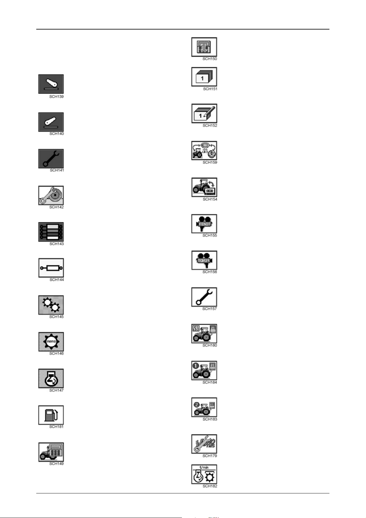
9. Front PTO ...............................................149
10. Transmission and axle drives...............149
10.1 Changing the transmission oil..................149
10.2 Checking the transmission oil level..........150
10.3 Changing the oil in the axle drives...........151
11. Four-wheel drive axle............................151
11.1 Changing the oil in the front axle
differential gear........................................151
11.2 Replacing the oil in front axle hub drives.152
11.3 Front axle suspension..............................152
12. Power lift.................................................153
13. Hydraulic system...................................153
13.1 Checking oil level in hyrdraulic system....153
13.2 Changing the hydraulic oil........................154
13.3 Hydraulic oil filter......................................154
14. Steering...................................................156
15. Front wheels...........................................156
15.1 Checking toe-in........................................156
16. Heating and ventilation .........................157
16.1 Removing the heater fan filter..................157
16.2 Replacing the roof fan filter......................157
16.3 Replacing the recirculating air filter..........158
17. Air conditioning .....................................158
17.1 Condenser ...............................................158
17.2 Compressor V-belt...................................159
18. Windshield washer system...................159
19. Cleaning the tractor...............................159
19.1 Clean the cab's air spring bellows............159
20. Electrical and electronic systems........160
20.1 Battery......................................................160
20.2 Alternator .................................................160
20.3 Electrowelding..........................................160
20.4 Adjusting the headlights...........................160
20.5 Adjusting the auxiliary headlampss..........161
20.6 Auxiliary lights, Xenon headlights............161
20.7 Additional installation of electrical and
electronic equipment................................162
IMPLEMENTS...............................204
1. Reversing device ...................................204
FAULTS AND REMEDIAL
ACTIONS........................................205
1. Warning and fault messages................205
1.1 Warning messages..................................205
1.2 Fault messages........................................211
1.3 Clearing a warning or fault message .......215
1.4 General faults...........................................216
2. Variotronic Ti fault messages...............223
3. Warning and information messages
for implement settings..........................227
4. Flame starting system faults ................228
5. Fault code tables....................................229
6. Emergency operation............................245
TECHNICAL DATA.......................247
1. Technical data........................................247
2. Tyre pressures.......................................251
3. Tyre combinations.................................252
4. Fuel and lubricants Vario 916 - 930......253
4.1 Bio-diesel.................................................254
4.2 Bio hydraulic oil........................................254
5. Lubrication chart....................................255
5.1 Filling points.............................................255
5.2 Lubrication points.....................................256
21. Fuses.......................................................163
21.1 Fuse holder X050.....................................164
21.2 Fuse holder X051.....................................165
21.3 Fuse holder F060 - F067 .........................166
21.4 Fuse holder (A013)..................................167
22. Wiring diagrams.....................................168
22.1 Legend for circuit diagrams......................168
22.2 Colour coding for electric wires................171
22.3 Wiring diagrams.......................................171
7
Page 8

NUMERICAL INDEX
8
Page 9

SAFETY INSTRUCTIONS
Safety and accident prevention regulations
WARNING:
Before every operation, check the tractor for road worthiness and operational safety.
Carefully read the Manual and observe all safety instructions.
Safety signs on the machine must be replaced if damaged or lost.
General safety and accident
prevention regulations
Text-module
1.Follow the general safety and accident
prevention regulations, as well as the safety
information in this manual.
2.When driving on public roads, follow the usual
traffic regulations!
3.Before starting work, familiarise yourself with
all operating controls and their functions. Don't
wait until after you have started working!
4.Start the engine from the driver seat only. Do
not attempt to start by shorting across the
starter terminals, as this can cause the tractor
to move immediately!
5.Before starting up, check the area is clear (e.g.
children). Ensure that nothing obstructs vision.
6.Never leave the engine running in a confined
space!
7.The driver should wear close-fitting clothing.
Avoid wearing loose-fitting garments!
8.Take extra care when handling fuel - serious
fire hazard. Never re-fuel in the presence of
sparks or naked flames. Do not smoke when
re-fuelling.
9.Before re-fuelling, turn off the engine and
remove the ignition key. Do not re-fuel in
confined spaces. Clean up spillages
immediately!
10.To avoid fire hazard, keep the tractor clean.
11.Beware of leaking brake fluid and battery
acid (these are toxic and corrosive).
ETNum-list
Carrying passengers
Text-module
1.Passenger should be carried only if the tractor
is fitted with an appropriate passenger seat.
2.Do not carry passengers in any other other
circumstances.
ETNum-list
Driving the tractor
Text-module
1.Driving speed must always be adapted to the
current situation. Avoid sudden cornering
when driving uphill or downhill, or across
gradients. Disengage the differential lock
when cornering. Never disengage the clutch to
shift gears when travelling downhill!
2.Make sure all trailers and implements are
properly hitched. Driving characteristics,
steering and braking are affected by mounted
implements, trailers and ballast weight.
Therefore, always ensure that there is
adequate steering and braking capacity.
3.Observe the maximum permissible gross
vehicle weight, axle loads and tyre load
capacity, especially if heavy implements are
attached.
4.When negotiating bends with implements
connected or hitched up, always allow for the
overhang and oscillating weight of the
implement.
ETNum-list
Front loader operation
Text-module
1.Never allow anyone to stand in the hazard
area, or within the working range of the front
loader. Keep the area clear of bystanders at all
times. Do not operate the front loader unless
there is a clear view of the entire working area
- illuminate the area if necessary.
2.It is not permitted to use the standard loader
(as supplied) as a working platform. If using
the loader with a special working platform,
additional safety measures are required.
3.Do not handle round bales, pallets etc. unless
the loader is suitably equipped for this
purpose. If loading objects that cannot be
secured and may fall off, do not use the front
loader unless the driving seat is protected by a
robust canopy.
9
Page 10

SAFETY INSTRUCTIONS
4.When the front loader is raised, the risk of the
tractor tipping over is greater, and the braking
effect at the rear axle may also be reduced.
Adapt your driving style and ensure adequate
ballasting at the rear. For additional loading,
we recommend attaching the Fendt 870 kg
additional weight at the three-point link - fit
wheel weights and fill the tyres if necessary.
5.Keep a safe distance from high-voltage
cables.
6.When on public roads, bring the front loader
into the transport position and secure it. Keep
a maximum distance of 3.5 m between the
implement and the centre of the steering
wheel. If the forward projection exceeds 3.5 m,
appropriate measures must be taken to
guarantee safe traffic conditions (e.g. use
people on foot acting as guides or mirrors at
road junctions). Transporting equipment or
materials with a front loader working
implement, e.g. a scoop, is not permitted when
travelling on public roads.
7.Danger from unintended lowering of the front
loader. Always secure hydraulic lever at the
end of operation. Before leaving the tractor,
completely lower the front loader to the
ground.
8.For safety reasons the front loader should be
mounted and removed by one person only , the
driver himself.
9.Always keep hands away from the crushing
and cutting areas while parts may still be
moving.
10.Detach the front loader with the attached
implement (bucket, fork) only on firm and
level ground. Always use the supports
provided.
1 1.The front loader must be parked and secured
in such a way as to prevent unauthorised
persons or children from causing it to tip over .
12.When mounting the front loader, connect all
hydraulic connections including the auxiliary
return, if equipped in this way. Always
connect hydraulic hose for cylinder load
pressure to +. Take great care not to confuse
connections since this may cause accidents
through reversed functions, e.g. lifting
instead of lowering. Before fitting the multiple
coupler, remove the load from hydraulic
hoses and unplug rear hydraulic
connections, lower the power lift and operate
only via EPC. Hydraulic fluid interflow can
create danger from unintentional equipment
motion.
ETNum-list
Leaving the tractor
Text-module
1.Make sure the tractor is properly secured
against running off (parking brake, wheel
chocks). Switch off the engine and apply the
hand brake!
2.Remove the ignition key and lock the cab if
necessary.
3.Never leave the tractor unattended while the
engine is running.
4.Never leave the cab while the tractor is in
motion.
5.Completely lower the mounted implement
before leaving the tractor.
ETNum-list
Mounted and trailing equipment
Text-module
1.Only attach implements and trailers using the
prescribed devices.
2.Use only trailers which comply with the
country-specific regulations. Do not exceed
maximum vertical bearing load. Ensure that
the tractor-trailer brake system is functioning
correctly.
3.Take special care when hitching trailers or
implements!
4.Secure trailers and implements to prevent
them rolling. Make sure that detached
implements and components are safely
parked.
5.Be sure all protection devices are correctly
attached and in the safety position before
operating the tractor.
6.When using the power lift, always remain well
outside the travel range of the three-point link
attachment!
ETNum-list
PTO operation
Text-module
1.Always switch off the engine, before fitting or
removing the drive shaft. The PTO shaft must
be in 0-position.
2.During PTO operations, allow no-one in the
vicinity of the rotating PTO or drive shaft.
3.Make sure drive shaft and PTO are equipped
with protective guards and sleeves.
4.After switching off the PTO, the attached
implement may continue running due to the
flywheel mass. In this case, do not go near the
implement. Approach it only when it has come
to a complete standstill.
5.When the drive shaft is removed, cover the
PTO shaft with its protective cap.
10
ETNum-list
Page 11

Maintenance
Text-module
1.Before maintenance and repair work, switch
off the engine and remove the ignition key.
Relieve pressure from implement lines, e.g. to
the front loader.
2.Any person should keep clear of a lifted,
unsecured load (e.g. tilted cab and similar).
3.Never open or remove any protection devices
while the engine is running.
4.Never grasp leaking pressure lines.
Pressurised fluids (diesel or hydr . oil) escaping
under high pressure can penetrate the skin
and cause severe injuries. If this has occurred,
seek medical advice at once to avoid the risk
of serious infection.
5.Keep at a safe distance from hot areas.
6.Hydraulic accumulator and connected pipes
are highly pressurised. Only remove and
repair in accordance with instructions provided
in Technical Manual.
7.To avoid eye injury, do not look directly at the
surface of the activated radar sensor.
8.Dispose of oil, fuels and filters properly!
9.For fitting tires, specialist knowledge and
special mounting tools are required.
10.Run the tractor for a short time, then
retighten all wheel nuts and bolts; check
them regularly. For correct torque values
refer to TECHNICAL DATA.
11.Before working on the electrical system,
always remove the ground strap from the
battery . Observe the following, when carrying
out electric welding. When carrying out
electric welding on tractor or mounted
implements, make sure that both battery
terminals are disconnected. Attach the
ground terminal as close as possible to the
welding point.
12.Spare parts must at least meet the technical
requirements stated by the manufacturer.
You can ensure that this is the case by using
genuine spare parts!
SAFETY INSTRUCTIONS
Text-module
Advice for front loader maintenance:
1.Before undertaking maintenance work, lower
the front loader to the ground, switch off the
engine and remove the ignition key.
2.If the pipe fracture protection has engaged,
support the load before starting repairs, and
slowly retract the cylinder.
3.Hydraulic hoses deteriorate with age. Check
the condition of hydraulic hoses at regular
intervals, and replace them in good time.
4.After attachment and repair operations, drive
the tractor for a short time then retighten all
mounting screws and nuts and check them
regularly.
5.Retighten eccentric bolt for front loader
attachment, if necessary.
ETNum-list
ETNum-list
11
Page 12
SAFETY INSTRUCTIONS
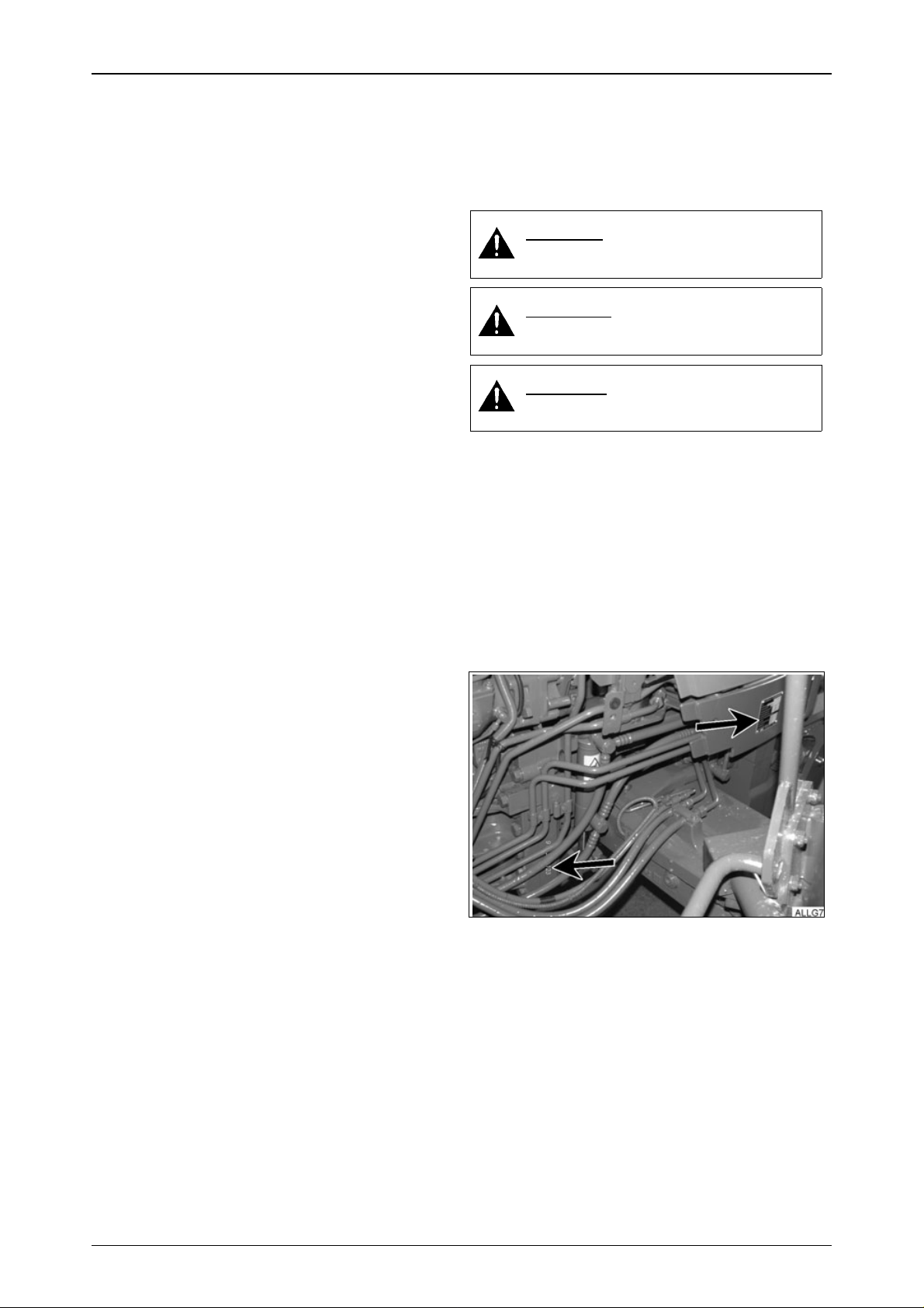
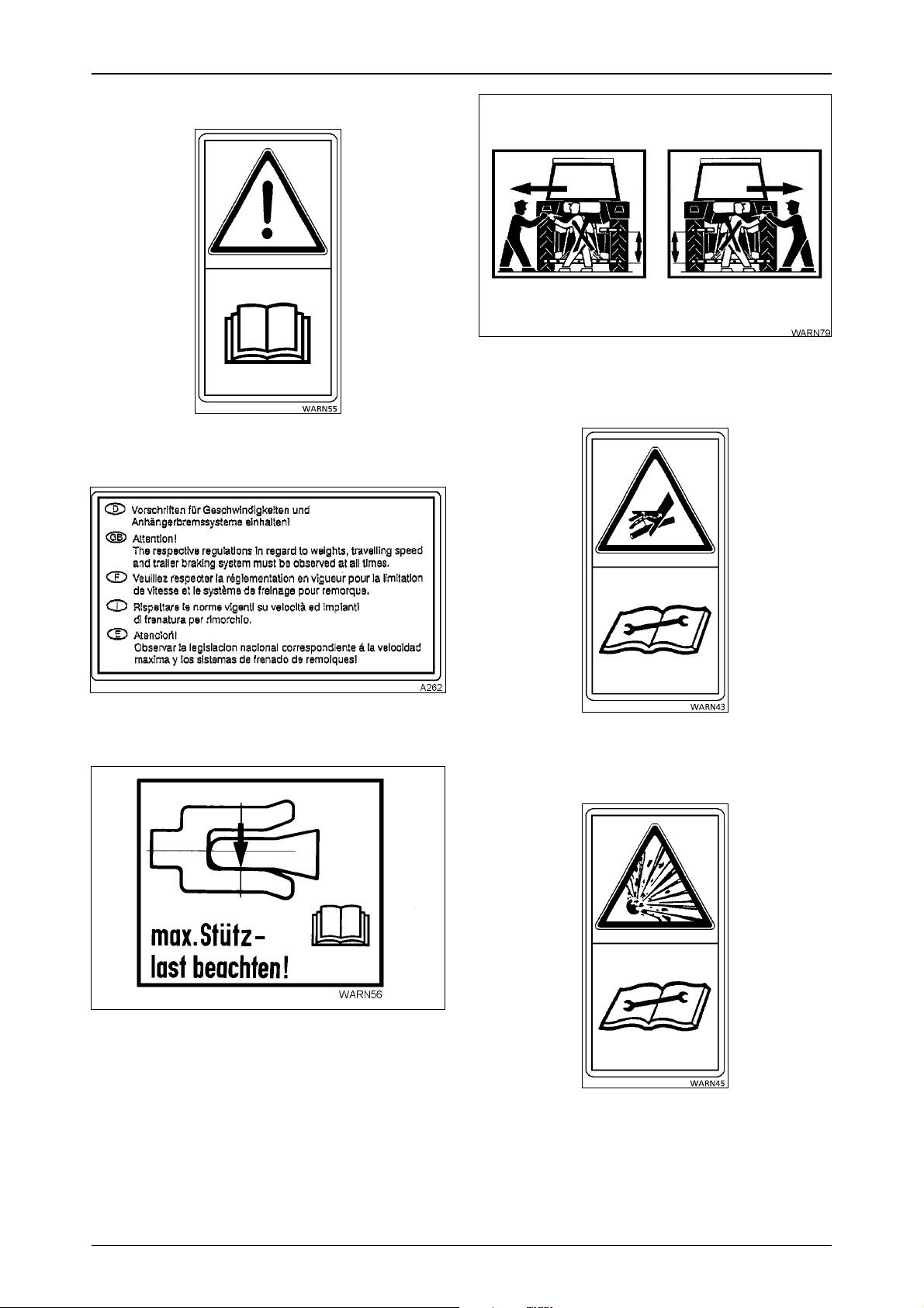
Location of safety signs
Operation_Pic_number:1
Fig.1
Inside the cab on the right.
Operation_Pic_number:1
Operation_Pic_number:1
Fig.4
On the left and right rear mudguards beside the
lifting gear control.
Operation_Pic_number:1
Fig.2
Inside the cab on the right.
Operation_Pic_number:1
Fig.3
On the right rear mudguard.
Fig.5
At left front of hydraulic cylinder of front axle
suspension.
Operation_Pic_number:1
Fig.6
On pressure reservoir of front axle suspension.
12
Page 13
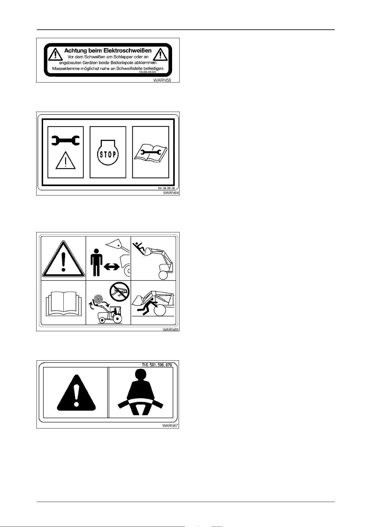
Operation_Pic_number:1
Inside the cab on left.
Operation_Pic_number:1
SAFETY INSTRUCTIONS
Fig.7
Fig.8
Inside the cab, on the cover of the emergency
operation controls.
Operation_Pic_number:1
Fig.9
On the front loader forks, left and right.
Operation_Pic_number:1
Fig.10
Inside the cab, on the left, on the transverse
beam of the front windscreen.
13
Page 14
OPERATION
1. Driver seat
WARNING:
Never adjust the seat while the tractor is moving (risk of accident).
If a seat belt is available, always attach it.
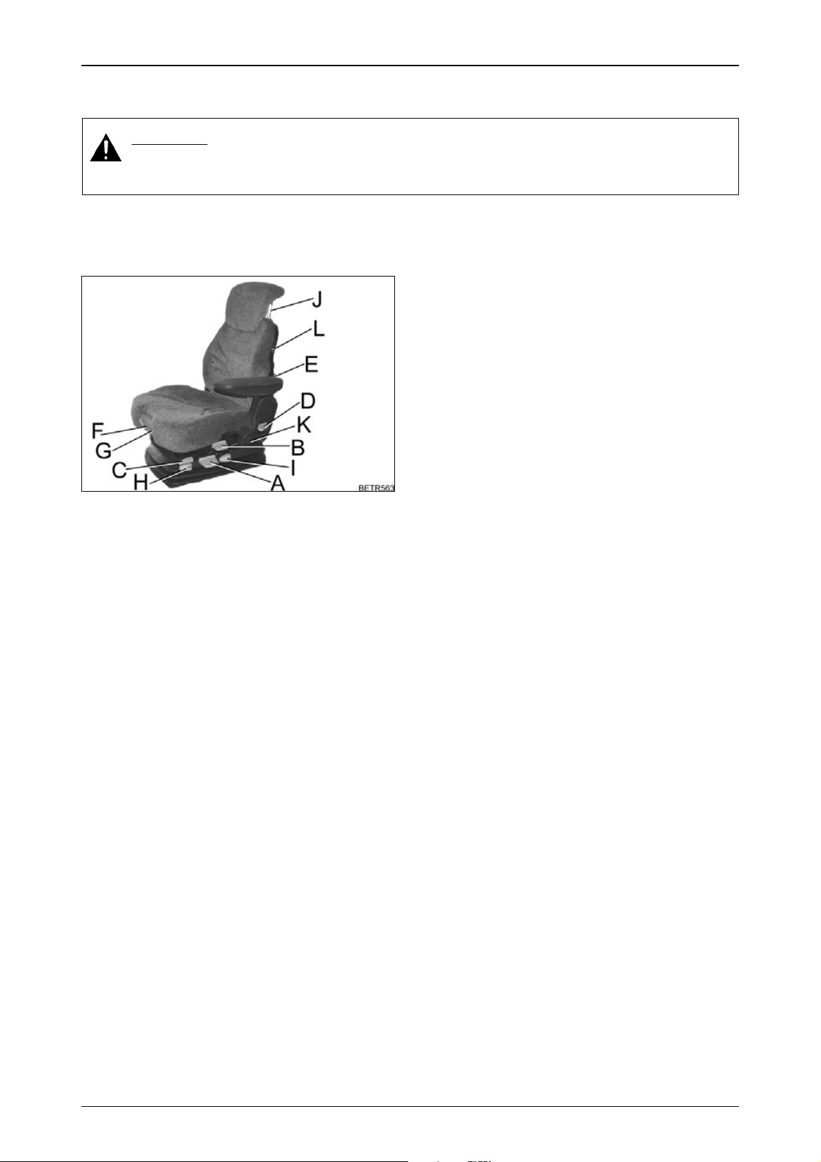
1.1 Super deluxe seat
Operation_Pic_number:1
Fig.1
Text-module
A = Automatic weight and height adjust-
ment.
B = Swivel mechanism.
C = Longitudinal adjustment.
D = Backrest adjustment.
E = Lumbar support (curvature), pneumatic
operation.
F = Seat bolster (depth adjustment).
G = Seat bolster (tilt adjustment).
H = Horizontal springing (on/off).
I = Vertical springing (adjustable from soft to
hard in four levels).
J = Backrest extension.
K = Behind the moulding:
Seat belt fixing point.
L = Seat heating.
14
Page 15
OPERATION
2. Display instruments and operating controls
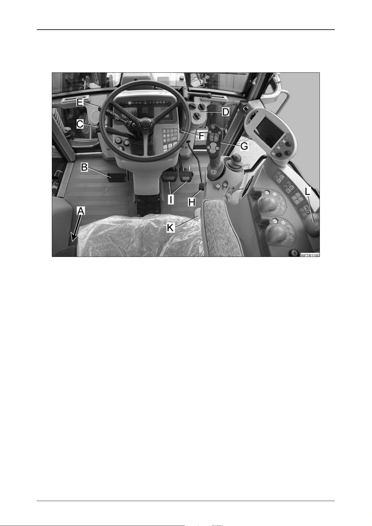
2.1 Front controls
Operation_Pic_number:1
Fig.2
Text-module
A = Hand brake
B = Clutch pedal
C = Steering wheel adjustment and quick reverse.
D = Heater and fan controls (see also OPERATION Section 3).
E = Combination switch
F = Heater starter switch
G = Multi-function armrest
H = Accelerator pedal
I = Brake pedals
K = Emergency operation controls (under the cover).
L = Hand throttle
15
Page 16
OPERATION
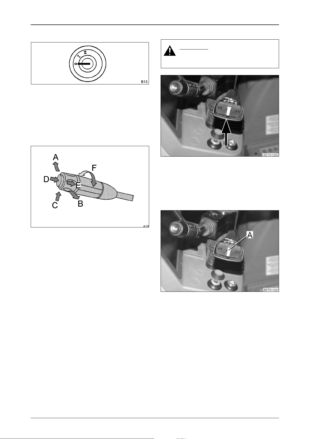
2.2 Glow and starter switch
Operation_Pic_number:1
Fig.3
Text-module
0 = Ignition off, key can be removed.
I = General ignition, key cannot be removed
+ preheating (automatic).
II = Starting + ignition.
2.3 Combination switch
Operation_Pic_number:1
2.4 Steering wheel adjustment
WARNING:
Never adjust the steering wheel
while the tractor is moving!
Operation_Pic_number:1
Fig.5
Text-module
● Pull up lever and adjust steering wheel to the
desired position (see also OPERATION Section 16).
Fig.4
Text-module
A = Right indicator.
B = Left indicator.
C = 1. With lights switched on: toggle low
beam, high beam.
2. With lights switched off headlight flas-
her.
D = Horn
E = Windshield washer system (wipers run
automatically).
F = Windshield wipers with intermittent and
continuous operation.
2.5 Quick reverse
Operation_Pic_number:1
Fig.6
● Press button (A).
The tractor slows to a standstill, then accelerates
in the opposite direction up to previous transmission ratio (see also OPERATION Section 7.6).
16
Page 17
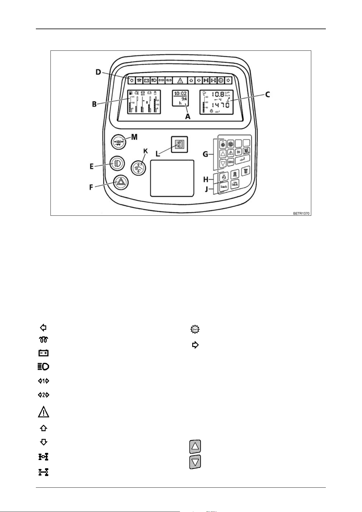
2.6 Dashboard
Operation_Pic_number:1
OPERATION
Text-module
A = Multiple display
B = Indication of fluid levels
C = Operating status display
D = Indicator lamps
E = Lights including side lights
F = Hazard warning flasher switch
G = Key pad for on-board computer (also
see OPERATION Section 26).
Text-module
Left turn signal indicator, green.
Preheater indicator lamp, red.
Alternator 2 not charging, red.
High beam, blue.
1st trailer light indicator, green.
2nd trailer light indicator, green.
Hazard light, red.
Forward direction of travel, green.
Reverse direction of travel, green.
4-WD engaged, green.
Fig.7
H = Key pad for rpm indicators (also see
OPERATION Section 2.8).
J = Key pad for speed display (also see
OPERATION Section 2.8).
K = Emergency mode (also see FAULTS
AND REMEDIAL ACTIONS Section 6).
L = Alternator 1 not charging, red.
M = Hydraulic trailer brake (optional), (see
also OPERATION Section 15.3).
Cruise control on.
Right turn signal indicator, green.
If one of the indicator lamps for forward/reverse
fails, back-up indicators can be activated on the
multiple display (A) activation (see see
OPERATION Section 26.5).
Text-module
Automatic dimmer
for forward/reverse indicator lamps, 4-WD, differential lock and related buttons.
At dusk or in the dark, the dimmer can be adjusted manually.
Brightness is increased or decreased by
pressing one of the two buttons.
Differential lock engaged, red.
17
Page 18
OPERATION
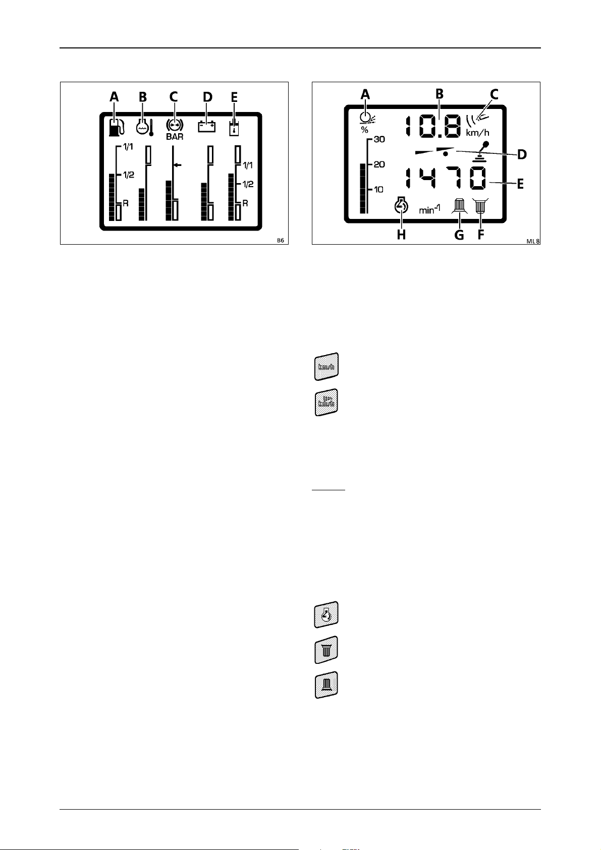
2.7 Indication of fluid levels
Operation_Pic_number:1
Fig.8
Text-module
A = Fuel supply
B = Engine temperature
When the bar indicators reach the red
zone, relieve the engine of load immediately and allow to cool down for about
2 minutes at 1000 rpm, then turn the en-
gine off.
C = Compressed air supply
D = On-board electrical system voltage
E = Hydraulic oil supply
2.8 Operating status display
Operation_Pic_number:1
Fig.9
Text-module
A=Wheel slip in %;
(only if optional radar sensor is equipped).
B=Tractor speed in km/h.
Text-module
On tractors with the optional radar sensor, use
these keys to change to:
theoretical speed measurement
calculated from transmission speed.
actual speed based on signal from radar
sensor, symbol (C) is lit.
Theoretical speed calculation is activated automatically when tractor speed is over
15 km/h, the wheel slip indicator (A) and symbol
(C) then go out.
NOTE:
For a precise reading, adjust the speed indicator under operating conditions (see also
OPERATION Section 26.2).
Text-module
D=Driving mode indicator
the selected driving mode is indicated by
a spot (D).
E=Rpm indicator
Text-module
can be changed with the buttons to:
engine speed symbol (H) is displayed.
rear PTO speed symbol (F) is displayed.
front PTO speed symbol (G) is displayed.
18
Page 19
OPERATION
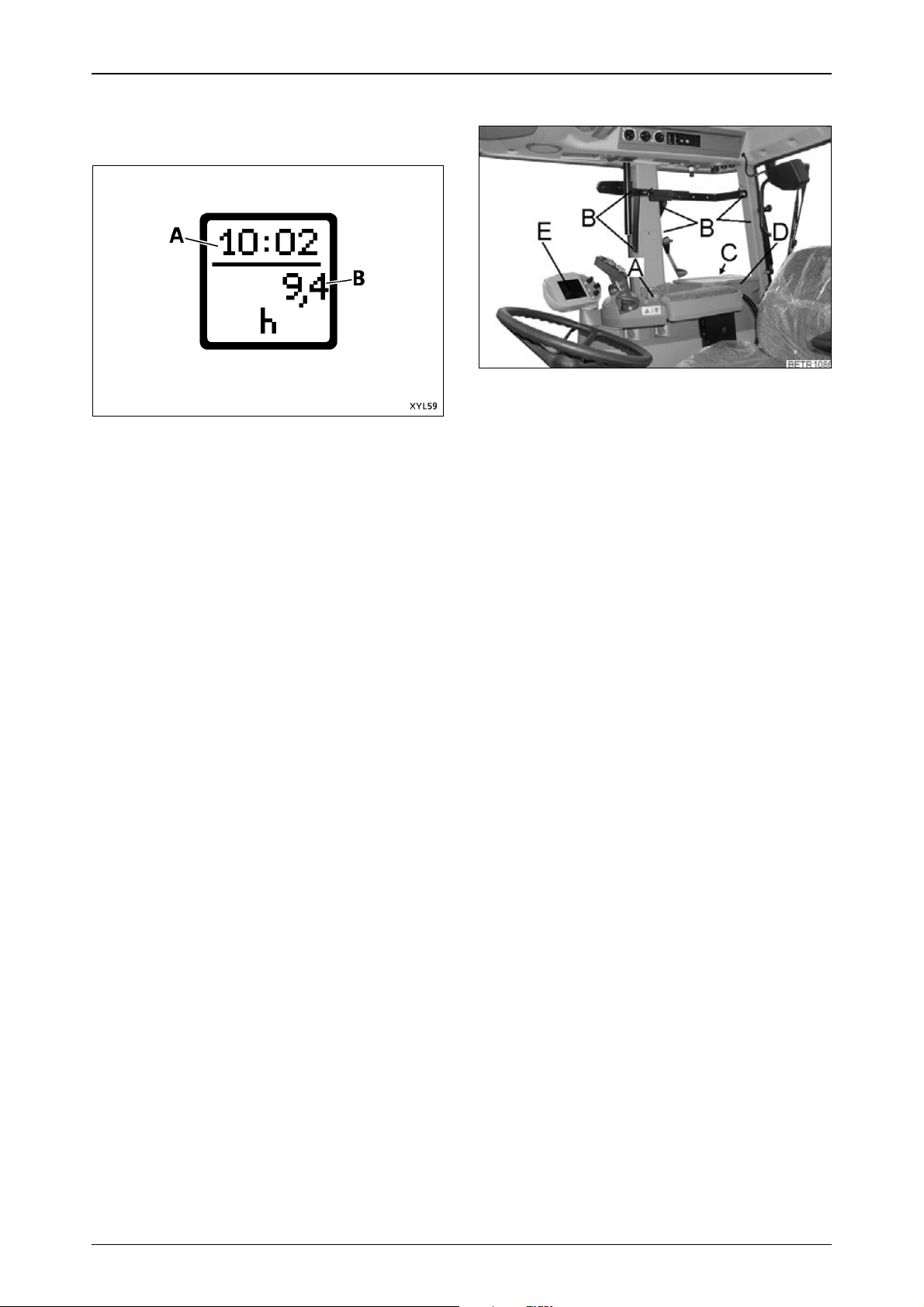
2.9 Multiple display
For warnings, fault messages and on-board
computer functions.
Operation_Pic_number:1
Fig.10
In the basic display, the clock (A) and operating
hours (B) are indicated. This is interrupted for
warnings, fault messages and on-board
computer functions.
2.10 Operating controls, right
Operation_Pic_number:1
Fig.11
Text-module
A = Hand throttle
B = Behind the moulding, M10 threaded ho-
les for fixing additional equipment, e.g.
radio or telephone, (see also CARE AND
MAINTENANCE Section 20.7).
C = Fuses
D = Document box
E = Control terminal
19
Page 20
OPERATION
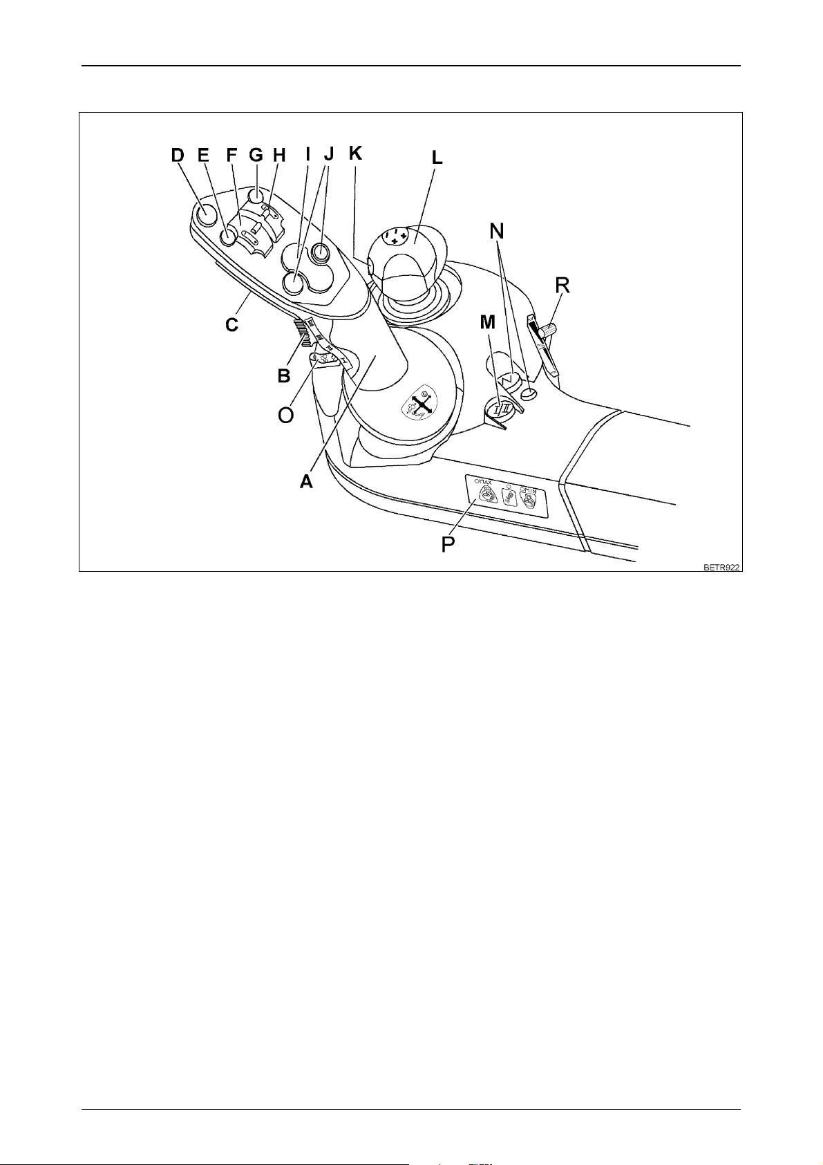
2.11 Multi-function armrest
Operation_Pic_number:1
Fig.12
Text-module
A = Joystick (see also OPERATION Section 7.1).
B = Acceleration rate selection (see also OPERATION Section 7.3).
C = Activating button on the back of the joystick.
D = EPC PTO automatic mode stop button (see also OPERATION Section 14.2).
E = Floating position of hydraulic valve, green or blue (see also OPERATION Section 17.3).
F = Lifting/lowering hydraulic valve, green or blue (see also OPERATION Section 17.3).
G = Floating position of hydraulic valve red or yellow (see also OPERATION Section 17.3).
H = Lifting/lowering of hydraulic valve red or yellow (see also OPERATION Section 17.3).
I = Rear power lift/ PTO automatic mode (see also OPERATION Section 14.2).
J = Front power lift/ PTO automatic mode (see also OPERATION Section 14.2).
K = 3rd hydraulic circuit on front loader.
L = Crossgate lever, lifting/lowering and floating position of hydraulic valves, yellow/blue or red/
green (see also OPERATION Section 17.3).
M = Driving mode selector (see also OPERATION Section 7.4).
N = Neutral button with neutral selected LED (see also OPERATION Section 7.2).
O = Accelerator pedal function (see also OPERATION Section 9.2).
P = Electronic engine control (also refer to OPERATION Section 9).
R = Accelerator pedal release (see also OPERATION Section 9.2).
20
Page 21
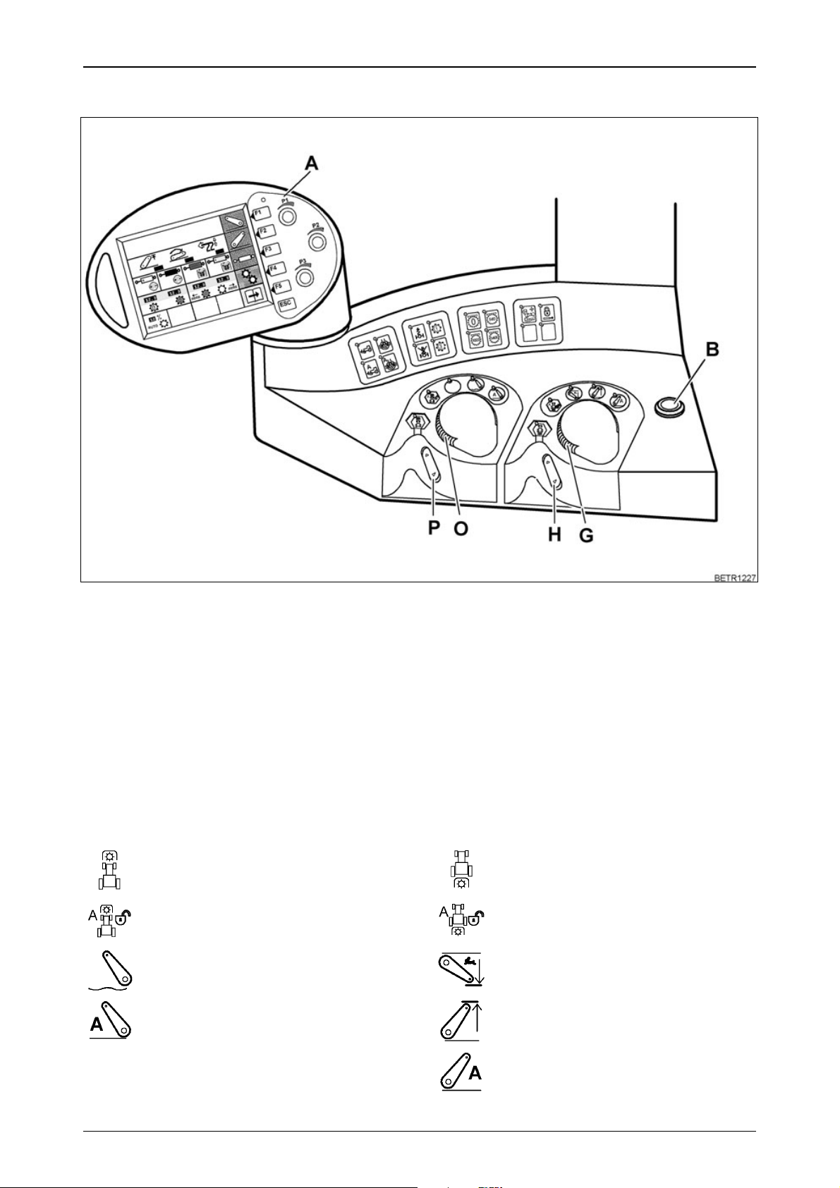
2.12 Operating console, right side
Operation_Pic_number:1
OPERATION
Fig.13
Text-module
A = Vario terminal (see also OPERATION Section 2.13).
B = Additional headlamps (on front of roof; can be switched on only when the headlamps are on -
these then go off).
G = Depth regulation rear power lift.
H = Quick lift rear power lift.
O = Comfort front power lift depth control.
P = Quick Lift, comfort front power lift.
Text-module
Front PTO and front power lift operation (see
also OPERATION Section 10.3, OPERATION
Section 20.3).
PTO ON/OFF
PTO automatic mode
Floating position
Text-module
Rear PTO and rear power lift controls (see
also OPERATION Section 10.1, OPERATION
Section 18).
PTO ON/OFF
PTO automatic mode
Quick insert
EPC automatic mode
Hitch-lift
EPC automatic mode
21
Page 22
OPERATION
Text-module
4-WD (see also OPERATION Section 11).
4-WD 100%; ON/OFF
4-WD automatic mode ON/OFF
Text-module
Differential lock (see also OPERATION
Section 12).
Differential lock 100 % ON/OFF
Differential lock automatic mode ON/
OFF
Text-module
Front axle suspension (also see OPERATION
Section 13).
Suspension locked
Suspension ON
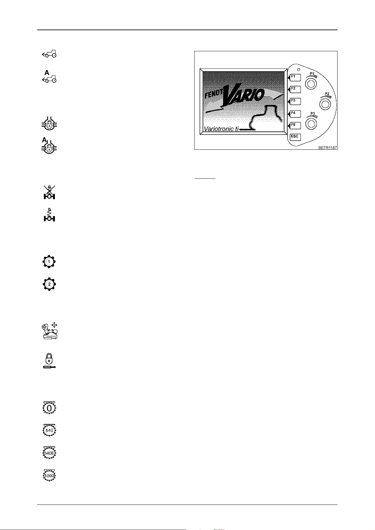
2.13 Vario terminal
Operation_Pic_number:1
Fig.14
Text-module
NOTE:
At low temperatures, a red-orange discolouration along with a decrease in contrast and
delayed display may occur for up to 20 minutes.
At high temperatures there may be a loss of
contrast.
Text-module
Tempomat cruise control (see also OPERATION Section 7.8).
Memory 1
Memorised speed 2
Text-module
Hydraulic valves (see also OPERATION
Section 17.3).
Hydraulic valve control
The operating functions of the crossgate
lever and the controls on the joystick are
interchanged.
Locking the hydraulic valves
Text-module
Speed preselection for rear PTO (see also
OPERATION Section 10.1).
PTO neutral
Text-module
After the start-up display , the following first main
menu is displayed.
PTO 540
Economy PTO (750)
PTO 1000
22
Page 23
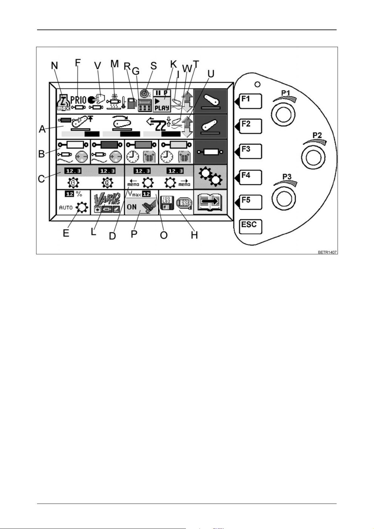
First main menu
Operation_Pic_number:1
OPERATION
Text-module
Pressing keys (F1 - F5) gives access to the following functions.
F1 = Comfort front power lift
F2 = Rear EPC
F3 = Electric valves
F4 = Transmission settings
F5 = Switch to 2nd main menu level
Display of prevailing operating status of:
A = Rear EPC
B = Electric valves
C = Cruise control
D = Programmed changes in direction of travel
E = Load limit control
F = Prioritised valve
G = Active on-board computer
H = LBS-ISO function (optional)
I = Front power lift - floating position
K = Variotronic Ti - function display
L = Tractor Management System
M = Hydraulic valve heating
N = Stored engine speed activated
O = Accelerator range
P = Accelerator pedal drive active
R = Measuring fuel consumption
S = Slip control active (optional)
T = Front EPC active
U = Rear EPC active
V = External valve actuation
W = Rear power lift - floating position
Fig.15
23
Page 24
OPERATION
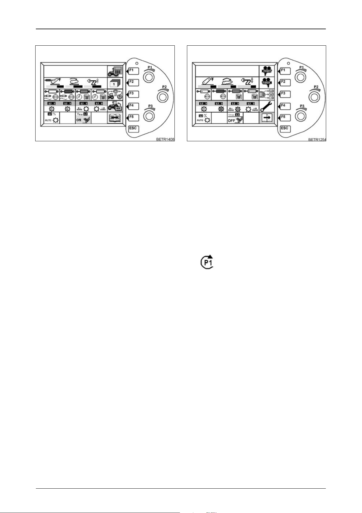
Second main menu
Operation_Pic_number:1
Fig.16
Text-module
Pressing keys (F1 - F5) gives access to the following functions.
F1 = On-board computer
F2 = Store terminal settings
F3 = Implement control
F4 = Variotronic Ti
F5 = Switch to third menu
Press the ESC key
● Display returns to first main menu.
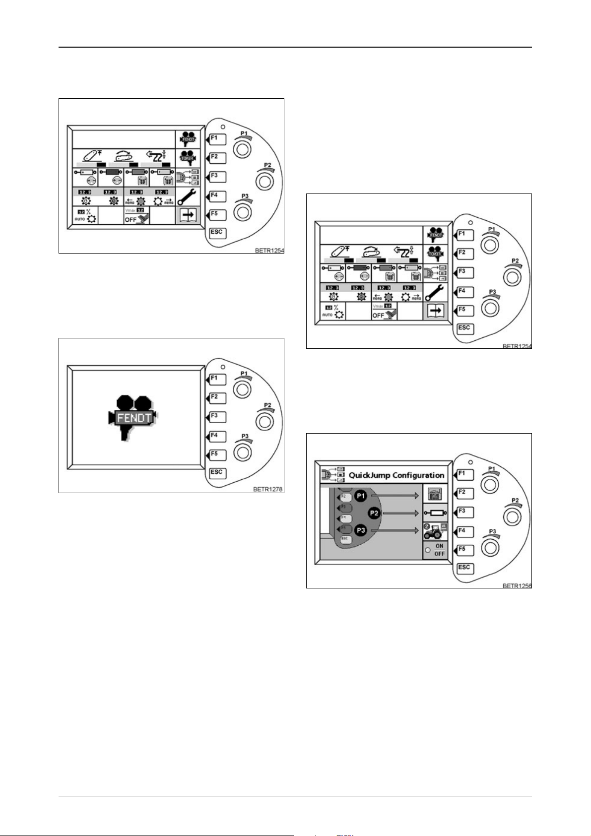
Third main menu
Operation_Pic_number:1
Fig.17
Text-module
Pressing keys (F1 - F5) gives access to the following functions.
F1 = Camera image (optional).
F2 = Camera image mirrored (optional).
F3 = Quick Jump
F4 = Terminal settings
F5 = Switch to first main menu
Text-module
Settings can be made with the 3 rotary controls
(P1, P2, P3) or
a preset menu page (Quick Jump) can be selected.
Text-module
The right rotary control for the
settings is displayed in the Vario
terminal.
Press the ESC key
● Display returns to first main menu.
24
Page 25
OPERATION
Adjusting screen brightness and
contrast
The brightness of the Vario terminal is
automatically adjusted.
Dimming can be adjusted steplesssly if
necessary.
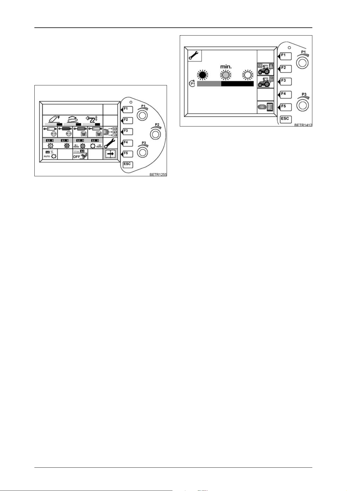
Operation_Pic_number:1
Fig.18
Text-module
It is set in the third main menu
● Press key F4.
Following sub-menu for terminal settings appe-
ars.
Operation_Pic_number:1
Fig.19
● Rotary control (P1) for setting degree of dimming.
Bar indicators:
right = no dimming.
left = max. dimming.
Any setting between the two positions is possible.
Text-module
Pressing keys (F1 - F5) gives access to the following functions.
F1 = No function.
F2 = Service function (LBS-ISO) for the work-
shop.
F3 = Service function for the workshop.
F4 = No function.
F5 = LBS-ISO (optional).
Press ESC key
● Display returns to first main menu.
25
Page 26
OPERATION
2.14 Camera function
Text-module
(optional).
Operation_Pic_number:1
Fig.20
● Press the F1 or F2 key.
Following sub-menu for terminal settings appe-
ars.
Operation_Pic_number:1
2.15 Quick Jump
Text-module
This function allows a preset menu page to be
selected directly from the first menu level.
Turning the rotary control (P1 - P3) slightly, selects the preset menu page.
Press ESC key
● Display returns to first main menu.
Selecting menu pages
Operation_Pic_number:1
Fig.21
Text-module
Press the ESC key twice.
● Toggles between main, implement and camera menus.
Setting brightness and contrast.
● Brightness can be set with the rotary control
(P1).
● Contrast can be set with the rotary control
(P2).
Fig.22
● Press F3 key.
Following sub-menu for terminal settings appe-
ars.
Operation_Pic_number:1
Fig.23
● Choose the desired menu page with the F2 F4 keys.
Press key repeatedly until the desired menu
page appears.
● Switch function on and off with the F5 key.
● LED lights up green - function is on.
Text-module
26
Page 27
OPERATION
Selection of the jump menu items
The jump menu items that can be selected, depend on the tractor equipment, e.g. if no front
power lift is fitted, this jump menu item is not
shown in the selection list.
Front power lift
Rear power lift
Rear power lift settings
Rear power lift settings, slip control
Overview of electrical valves
On-board computer 1- 4
Load implement settings
Only possible if Teach In and the
automatic modes for the power lift and
PTO are not active.
Save implement settings
Only possible if Teach In and the
automatic modes for the power lift and
PTO are not active.
Implement control
Only possible if implement being
installed.
Teach-in
Camera
Electrical valves 1-4
Cruise control, load limit control
Quick reverse
Engine speed min. - max.
Fuel consumption indicator
Camera image mirrored
Terminal settings
Implement control diagnostics
Tractor diagnostics 1
Tractor diagnostics 2
On-board computer overview
TMS settings
Page with speeds
27
Page 28
OPERATION
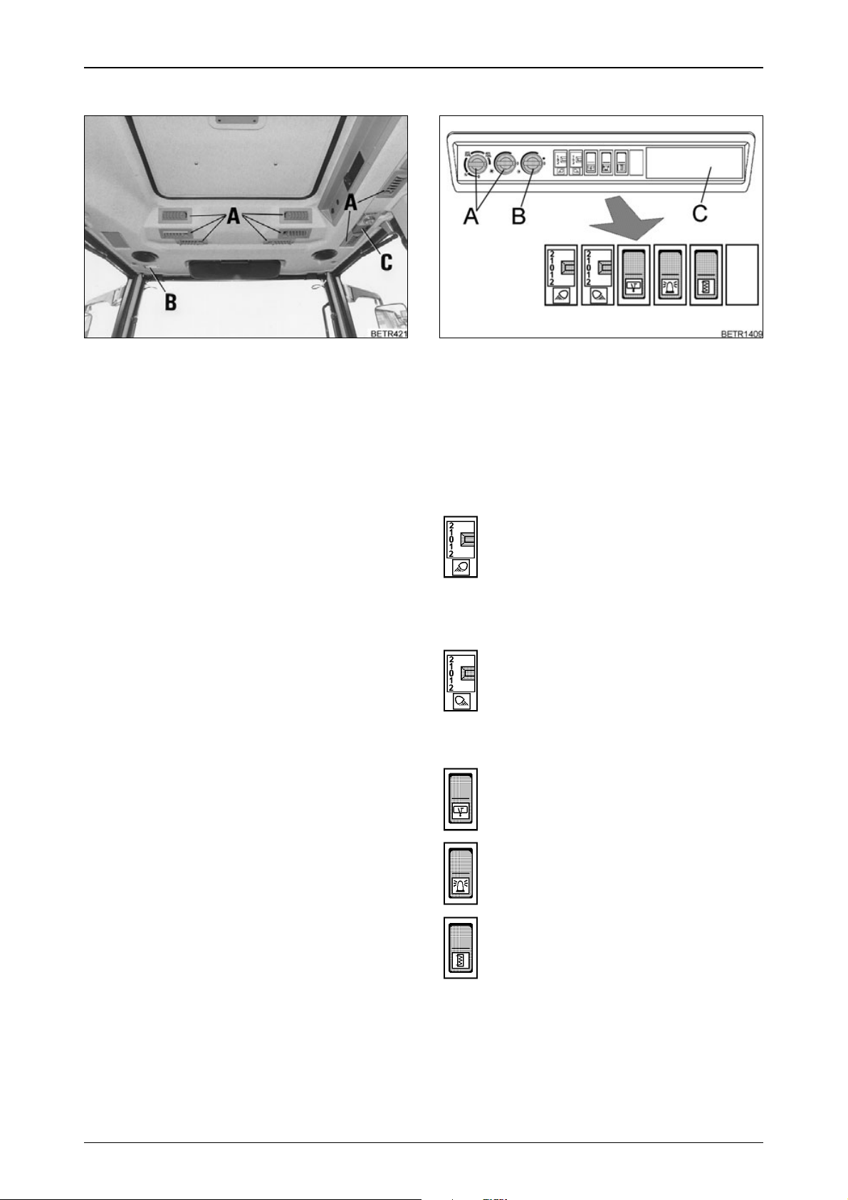
2.16 Cab top section, front
Operation_Pic_number:1
Fig.24
Text-module
A = Adjustable air nozzles
B = Cab lighting
C = Right-hand console lights
2.17 Cab top right side
Operation_Pic_number:1
Fig.25
Text-module
A = Auxiliary ventilation (see also OPERA-
TION Section 3.2).
B = Air conditioning ON/OFF and tempera-
ture control switch (see also OPERATION Section 3.3).
C = Space for radio installation, blanking pa-
nel. Connectors behind the panel are fitted as standard.
Work lamps at the front and at mirror
brackets:
2 = front and at mirror bracket.
1 = front.
0 = off.
1 = on rear view mirror bracket.
2 = front and at mirror bracket.
Working lights at the rear and on
mudguard:
2 = at rear and on mudguard.
1 = rear.
0 = off.
1 = on mudguard.
2 = at rear and on mudguard.
Rear window wiper and washing system.
Warning beacon.
Heated rear windshield.
28
Page 29
OPERATION
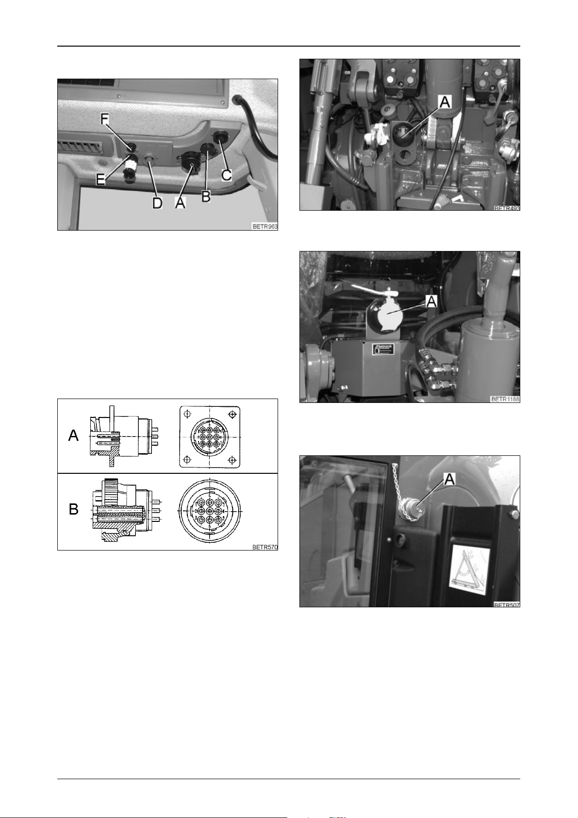
2.18 Power outlets
Operation_Pic_number:1
Fig.26
Text-module
A = 25 A constant current socket.
B = 10 A socket.
C = Implement socket.
D = Socket (blue) for external pulse counter .
E = LBS-ISO socket (optional) short circuit
plug must remain in place due to feedback.
F = Camera socket (optional).
Operation_Pic_number:1
A = Trailer socket.
Operation_Pic_number:1
Fig.28
Pin - attribution LBS-ISO implement
socket cabin
Operation_Pic_number:1
Fig.27
A = Connector within cabin.
B = Connector for LBS-ISO Terminal.
Pin 1 = not used.
Pin 2 = CAN Low input.
Pin 3 = CAN Low output.
Pin 4 = CAN High input.
Pin 5 = CAN High output.
Pin 6 = CAN-EN.
Pin 7 = Power supply for connected implement
(maximum load 5A).
Pin 8 = CAN GND.
Pin 9 = Ground connection for connected imple-
ment.
Fig.29
A = Electro-hydraulic external control:
Operation_Pic_number:1
Socket for external sensor.
Fig.30
LBS-ISO socket (A) rear (optional).
29
Page 30
OPERATION
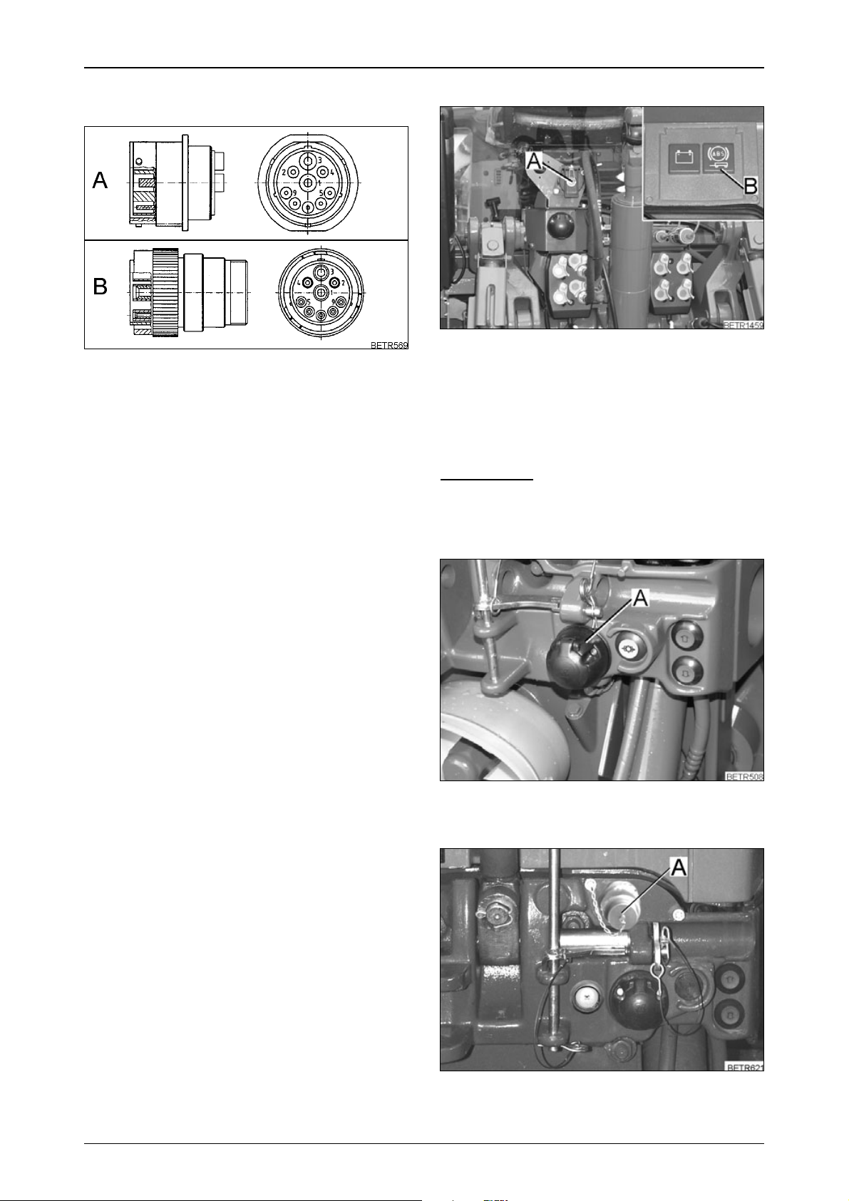
Pin - attribution LBS-ISO implement
socket rear and front
Operation_Pic_number:1
Fig.31
A = LBS-ISO socket for the mounted implement.
B = LBS-ISO connector for the mounted
implement.
Pin 1 = Earth 60A.
Pin 2 = Earth 25A.
Pin 3 = 60A power supply.
Pin 4 = 25A power supply for implement electro-
nics.
Pin 5 = Control signal for switching the end sy-
stem, bridged with pin 4 in the connector .
Pin 6 = CAN-EN.
Pin 7 = CAN GND.
Pin 8 = CAN High.
Pin 9 = CAN Low.
ABS socket (A)
Operation_Pic_number:1
Fig.32
1 = + UB 30
2 = + UB 15
3 = Earth electronics
4 = Earth tractor body
5 = Indicator lamp
IMPORTANT:
When turning the ignition ON or OFF, the indicator lamp (B) in the instrument panel must
light up briefly for monitoring purposes.
Operation_Pic_number:1
Fig.33
Socket (A) at front (with front power lift only).
Operation_Pic_number:1
Fig.34
LBS-ISO socket (A) front (optional).
30
Page 31

OPERATION
2.19 Reset function
Operation_Pic_number:1
Fig.35
Reset - initiate function.
● Press clutch pedal.
● Press push button (A).
To end Reset function.
● Stop the tractor.
● Switch ignition OFF/ON.
Text-module
When a reset is made, the following are restored to their basic settings.
● Cruise control (Memory 1 - final speed, Me-
mory 2 - 10 km/h).
● Load limit control (14% reduction to rated
speed).
● Valves (valid for all valves - lift 30 l, lower
30 l, time 10 seconds, floating position active).
● Rear lifting gear (upper limit 100% up, Trac-
tion/Position control 100% Position, lowering
speed 50%).
● Comfort front power lift (upper limit of tra-
vel 100% up, lifting speed 30 l, lowering
speed 5 l).
3. Heating and ventilation
3.1 Heater with 3-speed blower
Operation_Pic_number:1
Fig.36
The heating depends on the water temperature.
Switch on fan (control knob A).
Fan off.
Fan speed 1.
Blower speed 2.
Blower speed 3.
Directing the air stream (control knob C).
Air outlet nozzles closed.
through air vents in the footwell.
through air vents in the footwell and in
front of the windscreen.
through air outlet nozzles in front of
windshield, recirculated air mode on at the
same time.
Text-module
Switching on the heater (control knob B).
The control knob is ued to switch the cab heating
on/off, and for stepless adjustment to the desired
temperature.
NOTE:
If operating the air conditioning, set all control knobs to '0'.
31
Page 32

OPERATION
3.2 Auxiliary ventilation in cab
roof
Text-module
CAUTION:
When using the tractor for spraying
operations (e.g. weed or pest
control), fit filter cartridge
(aerosols). Use only fan speed 1.
After each spraying operation,
replace the filter cartridge with a
normal cartridge. Follow the
instructions given with the filter . Cab
and filter do not guarantee 100%
protection against harmful
chemicals. Follow the
manufacturer's instructions!
Operation_Pic_number:1
3.3 Air conditioning
WARNING:
All repair and maintenance work
must be carried out by qualified
personnel only.
Avoid all contact with liquid coolant.
If accidentally splashed in the eyes,
seek medical advice immediately.
No welding should be carried out on
or near any parts of the air
conditioning systems! Risk of
poisoning!
Maximum ambient temperature for
coolant 80 °C.
Check the V-belt only while the
engine is stopped. Attach the
protective grille again.
Operation_Pic_number:1
Fig.37
Text-module
Recirculated air/fresh air (A)
MIN = 100% recirculated air - 0% fresh air.
MAX = 0% recirculated air - 100% fresh air.
N = Normal setting approx. 80% recircu-
lated air - 20% fresh air.
0 = No fresh air.
The control knob position determines the mix
between recirculated and fresh air.
Text-module
Blower (B)
MIN = Minimum blower output.
MAX = Maximum blower output.
0 = Fan off.
Depending on the selector position, the blower
output can be increased steplessly.
Fig.38
● Start engine tractor (air conditioning only
works with the engine running).
● Switch on blower with selector (A).
● Switch on air conditioning with selector (B).
Indicator lamp (C) shows that the system is
working.
Text-module
The air flow is controlled by and directed through
nozzles (in cab roof cladding).
MIN = Minimum blower output, cooling
power.
MAX = Maximum blower output, cooling
power.
0 = Blower / air conditioning OFF.
Depending on the selector position, the blower
output and cooling power can be increased steplessly.
NOTE:
For health reasons it is advisable not to allow
the air inside the cab to drop by more than approx. 5 - 8 °C below the outside temperature.
Do not expose yourself directly to cold
draughts - danger of catching cold! For
energy economy and greater efficiency, we
recommend using the recriculated air mode.
32
Page 33

OPERATION
4. Rearwiew mirror
CAUTION:
Before driving the tractor and
starting work, adjust the mirror to
guarantee a clear view of the road
and of the working area to the rear.
Pull-out rearview mirror
Operation_Pic_number:1
Fig.39
● Adjust to tractor and/or trailer width using
screw (arrowed).
5. Start-up
5.1 Daily check
Text-module
Tractor must be in proper working condition.
Operation_Pic_number:1
Fig.40
● Check fuel level. If necessary , top up through
filler neck (A).
T op up with fuel after the day's operation to avoid
build-up of condensation. If it has run dry, bleed
the system.
● Check engine oil level (see also CARE AND
MAINTENANCE Section 3.4).
● Check transmission oil level (see also CARE
AND MAINTENANCE Section 10.2).
● Drain the water from compressed air bottle
(see also OPERATION Section 22.1).
33
Page 34

OPERATION
5.2 Cold weather operation
Text-module
Keep battery well charged; fill with winter fuel. At
temperatures below -12°C, add flow improver or
up to 30% petroleum.
Top up engine oil with HD-SAE 10W;
Antifreeze in coolant 35 - 50 vol.-%.
Engine warmer
(optional).
Operation_Pic_number:1
6. Starting and stopping
the engine
DANGER:
Start the engine from the driver seat
only. Never short circuit the battery.
Never leave the engine running in a
confined space!
Do not use priming fuel (e.g.
Startpilot)!
6.1 Memory function
● Start tractor.
● The following image appears.
Tractor in neutral position
(stationary)
Operation_Pic_number:1
Fig.41
● Connect engine warmer to mains supply
(220 V) using the cable supplied.
Warming time at least 3 hours, depending on
outside temperature. Preheating is only necessary in extreme cases.
Text-module
Compressed air system
● Open the antifreeze pump (see also OPERATION Section 22.1).
5.3 Tool box
Operation_Pic_number:1
Fig.43
Key F4 = Activate selected settings (see OPE-
RATION Section 28.1).
Key F5 = Activate the base settings.
If no key is activated, after about 10 seconds the
tractor's base settings are activated.
Fig.42
Removable tool box (A).
34
Page 35

OPERATION
Tractor in driving mode
If the tractor moves off immediately after it is
started, the following picture appears.
Operation_Pic_number:1
Fig.44
The selected settings (see OPERATION
Section 28.1) can not be activated.
Key F5 = Main menu appears.
The main menu appears automatically after
about 10 seconds.
6.2 Starting the engine
IMPORTANT:
Do not start or operate the tractor without a
battery. This could destroy the alternator.
Pay attention to warnings and fault messages. If necessary, switch off the engine immediately.
● Apply the hand brake.
● Depress clutch pedal (starting inhibit is deac-
tivated).
● Switch off PTOs and other drives.
● Electrical operating Switch off all consumers
if possible.
Operation_Pic_number:1
Text-module
or
The selected settings (see OPERATION
Section 28.1) should be activated.
Bring tractor to a standstill and press the neutral
button, further operation (see OPERATION
Fig. 43).
Fig.45
● Turn ignition key to position I, following symbols are illuminated:
● The LED neutral switch on the multi-function
joystick.
Charge indicator lamps.
Driving direction indicators.
Wait until preheat indicator flashes.
Steady light indicates preheating time.
● Turn ignition key to II and once the engine
has started, move it back to I.
● Battery charge indicator lamps must go out.
NOTE:
If at very low temperatures the engine does
not start within about 20 seconds, abort the
starting procedure, allow the starter to cool
down and wait for about 1 minute before trying again.
Switch off ignition before attempting to start
again.
Allow starter to cool down. Do not operate the
starter while the engine is still turning. In the
event of repeatedly unsuccessful starting attempts, refer to 'F AUL TS AND REMEDIAL ACTION'.
To avoid unnecessary white smoke, operate
the tractor at 1,000 rpm maximum for up to
5 minutes (depending on temperature). (Can
be driven with no load).
35
Page 36

OPERATION
NOTE:
The flame start control unit detects faults in
the flame starting system; these faults are indicated through various flash codes displayed on the preheating indicator (see
FAULTS AND REMEDIAL ACTIONS
Section 4.1).
6.3 Jump starting
WARNING:
A 24 V olt current destroys electronic
components.
Do not allow contact between the
non-insulated parts of the battery
clamps. The jump lead connected to
the positive terminal should not
come into contact with any
electrically conductive parts of the
vehicle - danger of shorting!
To avoid sparks, always attach the
jump lead clamps in the correct
order.
Use jump leads to connect positive terminal to
positive terminal and negative terminal to
negative terminal of the assisting battery.
Operation_Pic_number:1
Jump starting a partially discharged battery
with another battery.
● Connect jump leads to the assisting battery in
sequence (1-4).
● Start engine immediately.
● Once the engine is running, disconnect the
cables in reverse order.
If the attempt is unsuccessful.
● Connect jump leads to two assisting batteries
in sequence (1-8).
● Start engine immediately.
● Once the engine is running, disconnect the
cables in reverse order.
Text-module
NOTE:
Assisting batteries must have a voltage of
12 volts and around the same capacity (Ah)
as the discharged batteries.
When jump starting, the engine must be
started immediately after connecting, otherwise the assisting battery will become discharged as well.
Do not reverse the terminal polarity.
Use only jump leads with sufficient crosssection, and with insulated clamps.
Do not disconnect a discharged battery from
the on-board electrical system.
If the tractor is left unused for an extended
period, the battery can be recharged with a
battery charger (12V).
Fig.46
When battery partially discharged, jump starting from another tractor.
● Connect jump leads to the discharging tractor's battery in sequence (1-4).
● Start the engine of the second tractor.
● Start engine after ca. 15 minutes.
● Once the engine is running, disconnect the
cables in reverse order.
36
Page 37

OPERATION
6.4 Tow-starting
WARNING:
Tow-starting is not possible!
6.5 Stopping the engine
● Turn ignition key to position 0.
Text-module
NOTE:
After operating at full load, do not stop the engine immediately but allow it to cool down for
about 2 minutes at about 1000 rpm.
6.6 Stopping and immobilising
the tractor
WARNING:
Before leaving the tractor, apply the
hand brake, stop the engine, lower
hydraulic implements to the ground
and remove the ignition key. Make
sure the tractor is secured to
prevent it rolling. On slopes, chock
the wheels. If the tractor is left on a
public road, switch on the hazard
warning lights and place the hazard
warning triangle.
Hazard warning triangle
Operation_Pic_number:1
7. Vario transmission
7.1 Joystick
Operation_Pic_number:1
Fig.48
Text-module
A = Setting forward transmission ratio.
B = Setting reverse transmission ratio.
C = Change of direction of travel (forward/re-
verse using the joystick).
D = Tempomat cruise control ON.
7.2 Neutral position
WARNING:
Before leaving the tractor , make sure
the transmission is set in neutral
and engage parking brake.
If the engine is started or hand brake is applied,
the transmission shifts to Neutral position.
Operation_Pic_number:1
Fig.47
The hazard warning triangle (A) is attached
behind the driver seat (hazard warning triangle
not included as standard).
We would recommend ordering the warning
triangle from:
GEKA GmbH Germany 73054 Eislingen / Fils
Schloßstraße 97
Tel. 0049 7161/99903-0
Fax 0049 7161/99903-99
Fig.49
Text-module
● The transmission is neutralised or activated
with the neutral button (N).
Indicators with Neutral position selected.
1.LED (N1) lights up.
2.Travel direction indicator lamps (C) flash.
3.Clock and operating hours (D) indicators on
the multiple display.
37
Page 38

OPERATION
ETNum-list
Indicators when Neutral position is
disengaged.
1.LED (N1) is not lit.
2.Direction of travel indicator (C) are lit.
3.ACTIVE symbol indicator (E) on the multiple
display.
4.Warning light (F) flashes.
ETNum-list
7.3 Selecting acceleration rates
Operation_Pic_number:1
Setting acceleration rate I
Operation_Pic_number:1
Fig.51
Text-module
Procedure:
Press key, graphic (K) is displayed.
Press one of the keys repeatedly until
symbol (X) flashes.
Press key, graphic (W) is displayed, speed
is indicated in km/h.
Press one of keys repeatedly until the
desired value is displayed.
The indicated value is immediately
effective, press ESC to store the value.
Fig.50
Text-module
● Using the switch (arrowed), four different ac-
celeration rates can be selected, even while
moving.
With steady actuating of the joystick in one direction and at steady engine speed, driving speed
increases slowest in Rate I and fastest in Rate
IV.
In Rate I, the rate of change of speed can be set
at between 0.02 km/h and 0.5 km/h using the
keypad on the dashboard (at rated engine
speed).
The following table shows the change of speed if
the joystick is pressed once, and the time to reach maximum speed if the joystick is pressed
steadily, for the 4 acceleration rates.
Rate One push 0 to 50 km/h
I 0.02 - 0.5 km/h 250-45.5 secs
II 0.5 km/h 45.5 secs
III 1 km/h 23.8 secs
IV 2 km/h 10 secs
Values at engine rated speed.
Text-module
Press key repeatedly until clock and
operating hours are shown on the multiple
display.
Text-module
NOTE:
The acceleration rate cannot be set when
neutral position is switched off.
Text-module
Recommended use
Rate I = Use for specialist operations, e.g. ro-
ad-milling machine.
Rate II = Use in field work, heavy traction
work.
Rate III = Use in field work, heavy traction
work.
Rate IV = Use for transport operations.
NOTE:
When the cruise control is on, the time to reach the stored speed depends on the acceleration rate selected. Position I is not programmable.
38
Page 39

OPERATION
7.4 Driving mode selector
WARNING:
When selecting driving mode,
tractive power is interrupted. Do not
use on slopes (uphill or downhill).
Operation_Pic_number:1
Fig.52
The currently selected mode is indicated by a
spot (A). The selected mode is indicated by a
flashing spot.
Text-module
● The driver can use button (M) to switch from
range I to range II.
NOTE:
The last range selected is always set, even after turning the ignition on or off.
Text-module
Switching when tractor stationary
● Select Neutral position or
● operate clutch pedal.
● Select the desired mode.
Text-module
Selecting driving mode I or II while
travelling
Driving mode selection is not possible if:
● Neutral position is engaged.
● Transmission oil temperature below 10°C.
● Engine brake actuated.
Text-module
Switching from operating range II to I
when travelling
Driving mode selection is not possible if:
● Ground speed over 20 km/h.
● Neutral position is engaged.
● Engine speed over 2300 rpm.
● Transmission oil temperature below 10°C.
● Engine brake actuated.
NOTE:
In unfavourable conditions, e.g. cold weather ,
selecting a driving mode may simply cause
the neutral position to be selected. Interruption of tractive power, repeat driving mode
selection with button (M/ OPERATION
Fig. 52).
Cruise control and Quick Reverse function
deactivated.
RANGE I (field)
For heavy field use at a speed of:
0.02 - 32 km/h forward.
0.02 - 20 km/h in reverse.
Text-module
RANGE II (road)
For fast transport at speeds of:
0.02 - 50 km/h forward.
0.02 - 38 km/h in reverse.
Text-module
39
Page 40

OPERATION
7.5 Driving the tractor
WARNING:
Always engage the gears when
travelling downhill. Do not select
neutral.
At engine speeds over 2600 rpm, the
transmission ratio is no longer
reduced; to reduce speed, apply the
brake.
Operation_Pic_number:1
Turboclutch
The transmission control includes a turboclutch
function. This allows the tractor to be stopped
with the accelerator pedal.
This means:
1.No engine stalling under difficult conditions.
2.No wheel spinning.
3.Full power transmission from approx.
1,250 rpm engine speed.
ETNum-list
Deactivating turboclutch function
Operation_Pic_number:1
Fig.53
Text-module
Starting off forward from a standstill:
● Press and hold the activating button (C, on
back of joystick).
● If the joystick is moved forward, the tractor
moves off and accelerates forward.
● If the joystick is released, it automatically returns to center position and speed remains
constant.
● If the joystick is pulled back, the tractor slows
down and braking is applied until it comes to
an actuated standstill.
Text-module
Reversing from a standstill:
● Press and hold the activating button (C, on
back of joystick).
● If the joystick is pulled back, the tractor will
move off in reverse and accelerate.
● If the joystick is released, it automatically returns to center position and speed remains
constant.
● If the joystick is moved forward while reversing, the tractor slows down and is positively
braked until it comes to a standstill.
Text-module
NOTE:
It is also possible to operate the joystick first,
then press the activating button afterwards.
NOTE:
Optionally, a warning beep sounds when driving in reverse.
Text-module
Fig.54
● Press key (F4). The following sub-menu appears.
Operation_Pic_number:1
Fig.55
Required conditions:
1.Engine is running.
2.No current fault messages.
3.Transmission in neutral.
4.System not in emergency operation.
ETNum-list
● Pressing key (F2) switches turboclutch
function on and off.
When the function is on, symbol (A) appears as
shown, when the function is off, the symbol is
shown with a red cross superimposed.
After every cold start, the turboclutch function is
automatically activated again.
Text-module
40
Page 41

OPERATION
Driving off using the turboclutch
function
● Setting the engine idle speed.
● Apply the brake.
● Press activating button and use the joystick to
select the desired direction of travel.
● Release the brake and start off by accelerating slightly.
● Use the joystick to obtain the desired ground
speed.
NOTE:
Avoid stopping for long periods (>1 min.) with
the turboclutch on.
When operating with sustained load, do not
allow the engine speed to drop below
1,250 rpm.
Do not operate the clutch pedal for long periods.
Text-module
Stopping and starting on slopes
● Move joystick against the actual travel direction.
The tractor slows down until it comes to a standstill. 'Active' symbol flashes.
NOTE:
Below an engine speed of 1,250 rpm, depending on load, turbo clutch function will allow
transmission slip.
Text-module
Clutch pedal
For connecting implements, the tractor can be
controlled for gradual movements with the clutch
pedal.
In sudden emergencies, the tractor can be stopped by pressing the clutch and brake pedals.
Text-module
Final speed control
Final speed is a cruise control function which
compensates for variations in engine speed.
TEA
about 33 km/h 32.5 km/h 31 km/h
about 44 km/h 43.5 km/h 42 km/h
about 51 km/h 50.5 km/h 49 km/h
T = Theoretical final speed
E = Switch-on speed
A = Cut-out speed
The speed control is terminated by operating
any of the following:
1.Joystick
2.Brake pedals (including independent wheel
brake)
3.Engine brake pedal
4.Clutch pedal
ETNum-list
41
Page 42

OPERATION
7.6 Changing direction of travel
The tractor slows to a standstill, then accelerates
in the desired direction until the previous transmission ratio is reached.
The change of direction may be activated by:
- with the button on the steering wheel adjustment.
- with the joystick.
Text-module
Direction changing is cancelled when the
following are operated:
1.Joystick.
2.Neutral button.
ETNum-list
The following factors will block the function,
but not terminate it:
1.Load limit control.
2.Final speed limit.
3.Engine speed above 2,600 rpm.
4.Turboclutch function.
ETNum-list
IMPORTANT:
An incomplete Quick Reverse operation is indicated by flashing direction of travel indicators. The selected change of direction is activated as soon as the problem is solved.
NOTE:
According to the selected acceleration rate,
the reverse will be executed more or less rapidly.
Change of direction of travel using
button on the steering wheel lever
Operation_Pic_number:1
The tractor slows to a standstill. When the button
(A) is released, the tractor continues in the previous travel direction and with the previous
transmission ratio.
Changing the direction of travel
using the joystick
Operation_Pic_number:1
Fig.57
Text-module
● Press and hold the activating button (C, on
back of joystick). While the tractor is moving,
push the joystick to the left.
If no change of travel direction has been programmed (see also OPERATION Section 7.7),
the tractor slows to a stop and accelerates in the
other direction of travel until it reaches the transmission ratio that was active in the initial direction.
While the tractor is slowing, the preselected direction of travel is shown by flashing of the corresponding indicator (B), and the current travel
direction by a steady light.
Fig.56
● Move the button (A) forwards or backwards.
The tractor slows down to a standstill and acce-
lerates in the opposite direction until it reaches
the previous transmission ratio.
● Keep the button (A) pressed forwards or
backwards.
NOTE:
Optionally, a warning beep sounds when driving in reverse.
42
Page 43

OPERATION
7.7 Programmed changes of
travel direction
Text-module
NOTE:
The set values are only reached at an engine
speed of 1800 rpm.
Text-module
Using the control terminal, a forward speed and
a reverse speed can be pre-programmed.
Operation_Pic_number:1
Fig.58
Operation_Pic_number:1
Fig.60
The set speeds are indicated by the indicators
(A and B).
(C) shows actual speed; below 0.5 km/h, the
values change from km/h to m/h.
Indicator from 100 m/h to 500 m/h.
Setting speeds
● Select forward speed with rotary switch (P1).
● Select reverse speed with rotary switch (P2).
Set values are shown on the display (A / C).
Function display (B / D).
Indicator red, speed programmed for change in
direction of travel.
Indicator white, speed not programmed for
change in direction of travel.
● Press key (F4). The following sub-menu appears.
Operation_Pic_number:1
Fig.59
● Press key (F1). The following submenu appears.
Activating the selected speed
Operation_Pic_number:1
Fig.61
Activating stored forward speed
● Press key (F1).
● Display (A) changes from white to red.
Activating stored reverse speed
● Press key (F2).
● Indicator (B) changes from white to red.
Function indicator also appears on the first main
menu (see OPERATION Fig. 58).
43
Page 44

OPERATION
Actuating the stored speed
Operation_Pic_number:1
Fig.62
Text-module
NOTE:
The set values are only reached at an engine
speed of 1800 rpm.
Text-module
● With the vehicle moving, push the activating
button (C) and move joystick to the left (towards the driver seat).
7.8 Cruise control
NOTE:
T empomat cruise control only possible at an
engine speed above 1,300 rpm.
With cruise control, current speed is maintained
without storing.
In addition, two speeds can be stored to allow
the tractor system to be configured for two different situations, such as field work and road travel.
Once stored, the cruise control actuates one of
the stored speeds.
The stored speed is reached within a time that
depends on the acceleration rate selected (see
also OPERATION Section 7.3).
Maintaining current speed
Operation_Pic_number:1
NOTE:
If a direction change has been programmed,
the tractor slows to a stop and accelerates in
the opposite direction until it reaches the programmed transmission ratio.
NOTE:
Optionally, a warning beep sounds when driving in reverse.
Fig.63
NOTE:
No speed must be stored via one of the keys
(A or B).
44
Page 45

OPERATION
Operation_Pic_number:1
Fig.64
Text-module
● Accelerate to the desired speed.
● Move the joystick briefly to the right (away
from driver seat).
Indicator lamp (A) is lit, speed is displayed for 3
seconds on the multiple display (B).
Current speed now remains constant, irrespective of engine speed.
Operation_Pic_number:1
Fig.66
Text-module
Stored speeds are shown on the displays
(A and B).
● Turn rotary switch (P2) to set speed in memory 1 (indicator A).
● Turn rotary switch (P3) to set speed in memory 2 (indicator B).
Selecting speeds
Operation_Pic_number:1
Storing speeds
The stored speeds are maintained even after the
ignition is switched off.
Operation_Pic_number:1
Fig.65
Set values are shown on the display (A / C).
Function display (B / D).
Indicator violet, speed programmed for cruise
control.
Indicator white, speed not programmed for
cruise control.
● Press key (F4). The following sub-menu appears.
Fig.67
Text-module
Pre-selecting when T empomat cruise control
is not activated.
● Briefly press key (A) (Memory 1) or key (B)
(Memory 2).
The corresponding LED next to the key lights up.
Depending on preselection, indicator 1 or 2 is lit
violet (see OPERATION Fig. 66).
Depending on preselection, indicator B or D is lit
violet (see OPERATION Fig. 65).
A pre-selected speed can be cancelled by re-ac-
tivating the respective key.
45
Page 46

OPERATION
Actuating the preselected speed
Operation_Pic_number:1
Fig.68
Text-module
● While the tractor is moving, move the joystick
briefly to the right (away from driver seat).
Depending on preselection, indicator 1 or 2 is lit
green (see OPERATION Fig. 66).
Depending on preselection, indicator B or D is lit
green (see OPERATION Fig. 65).
Memorised selected speed is activated and remains constant independent of the engine
speed.
7.9 Load limit control
The load limit control is activated automatically if
engine speed drops under load. To do this, the
tractor automatically uses the transmission control to reduce the vehicle speed so that engine
speed does not drop any further.
Setting load limit control
Operation_Pic_number:1
Fig.69
● Press key (F4). The following sub-menu appears.
Operation_Pic_number:1
By adjusting the stored speed with the appropriate rotary control, Tempomat cruise control
speed can be adjusted to operating conditions.
When operating the other memory button (OPERATION Fig. 67/A,B), the cruise control adjusts
to the new target speed.
Indicator lamp (A / see OPERATION Fig. 68) is
lit, speed is indicated on the multiple display (B /
see OPERATION Fig. 68) for 3 seconds.
NOTE:
Memorised speeds can only be activated
while the tractor is moving.
The stored speed can be actuated in both driving modes and both directions of travel.
If the selected speed is not reached, check
the setting for the load limit control.
Text-module
Cruise control function remains active until
one of the following occurs:
1.clutch pedal is depressed.
2.brake pedal is depressed (also individual
wheel brake).
3.joystick is activated.
4.neutral key is activated.
5.engine brake is activated.
6.engine speed falls below 1,300 rpm.
7.a driving mode is selected.
Fig.70
Text-module
The set engine load limit is displayed by the bar
indicator (C), e.g. 14 %.
● The rotary control (P1) can be used to set engine load between 0 % - 30 %.
The setting is effective immediately. In this way,
the tractor can be adapted to the current situation during operation.
The load limit control only changes the transmission ratio to slower. Re-accelerating, once the
engine speed rises again, can either be done
manually using the joystick or automatically with
the cruise control function.
ETNum-list
46
Page 47

OPERATION
7.10 Storing engine speeds
Two engine speeds can be stored using rotary
controls (P1/P2) on the Vario terminal.
e.g. Speed 1 working speed - full throttle.
e.g. Speed 2 standing speed - idle.
Operation_Pic_number:1
Fig.71
● Press key (F4). The following sub-menu appears.
Operation_Pic_number:1
Stored engine speeds are indicated on the displays (A and B).
NOTE:
The maximum engine speed that can be set is
the engine limit speed.
The minimum engine speed that can be set is
the idle speed.
The value set can be exceeded with the accelerator.
Read the stored engine speed
Operation_Pic_number:1
Fig.72
● Press key (F3). The following submenu appears.
Operation_Pic_number:1
Text-module
Fig.74
Read the stored higher engine speed
(e.g. working speed - full throttle). LED is
lit.
Activating engine management (see
OPERATION Section 9).
Reading out the lower stored engine
speed (e.g. headland speed - idle). LED
is lit.
Fig.73
Text-module
● Set engine speed 1 in Memory 1 (display A)
with rotary control (P1).
● Set engine speed in Memory 2 (indicator B)
with rotary switch (P2).
47
Page 48

OPERATION
Operation_Pic_number:1
Fig.75
● Indicator (A) appears on the Vario terminal,
indicating active stored engine speed.
Text-module
Engine speed storing is terminated if one of
following conditions is present.
1.Speed over 18 km/h and foot brake is
operated.
2.Speed over 18 km/h and engine brake is
operated.
3.Call-up buttons are activated again.
4.Hand throttle is operated.
ETNum-list
8. Fuel consumption measurement
(also refer to OPERATION Section 27.4).
8.1 Activating fuel consumption measurement
Operation_Pic_number:1
Fig.77
● Press key (F4). The following sub-menu appears.
Operation_Pic_number:1
7.11 Towing instructions
Operation_Pic_number:1
Fig.76
● Open cover from the cab floor and remove.
● Attach auxiliary device to range control switch
(C).
● Put transmission into neutral position (centre
position).
NOTE:
Do not exceed a towing speed of 10 km/h.
Maximum towing distance 8 km.
Fig.78
● Press key (F4). The following sub-menu appears.
48
Page 49

Operation_Pic_number:1
Fig.79
A = Current fuel consumption.
B = Average fuel consumption.
Measurement at tractor START or
Press button (F3). Display is reset to '0'.
C = 1. Unit counter (e.g. for comparing the
same operation when different driving
styles are used).
Measurement at tractor START or
Press key (F4). Display is reset to '0'.
D = 2nd sum counter (e.g. comparisons of
the same work done with different driving methods).
Measurement at tractor START or
Text-module
Press key (F5). Display is reset to '0'.
NOTE:
Maximum value for the sum counter is
30000 litres, then measuring starts at 0 again.
OPERATION
9. Tractor Management
System (TMS)
Text-module
MODE 1
Joystick - engine management system off
The transmission ratio is set with the joystick, the
engine speed is set with the accelerator.
Text-module
MODE 2
Joystick - engine management system on
Driving speed is set with the joystick; the engine
speed and transmission ratio are set automatically.
NOTE:
If the TMS is active and change of direction is
programmed, the speed is taken up independent of the engine speed.
Text-module
MODE 3
Accelerator - engine management system off
The transmission ratio and the engine speed are
set with the accelerator.
Text-module
MODE 4
Accelerator - engine management system on
Driving speed is set with the accelerator; the engine speed and transmission ratio are set automatically.
NOTE:
If TMS is active and there is a programmed
change of travel direction, only the current
speed is obtained.
49
Page 50

OPERATION
9.1 Engine management system
CAUTION:
If engine management is active, the
engine speed can increase to maximum engine speed.
NOTE:
Engine speeds settings made with the hand
throttle potentiometer can be exceeded, but
speed will not go below the set speed.
Text-module
NOTE:
If the TMS is active, the Tempomat cruise
control function has no engine speed limit
(e.g. the Tempomat cruise control can even
be activated at idling speed).
Operation_Pic_number:1
9.2 Accelerator mode
Activating the accelerator pedal
function
Operation_Pic_number:1
Fig.82
● Press button (A) forward.
B = Indicator appears on the Vario terminal.
C = Indicator appears on the multiple dis-
play.
Fig.80
NOTE:
If stored engine speeds are activated using
the memory keys (A), the speed will not exceed or fall below the set speeds, even with
the engine management system engaged
(e.g. when working with the PTO).
Switching on the engine management system
Operation_Pic_number:1
NOTE:
When the accelerator function is engaged,
the Tractor Management System (TMS) is
switched on in the basic setting.
Text-module
Switching off the accelerator function
● Press key (A) backwards.
Text-module
Function displays
On the multiple display.
Appears for about 2 seconds
when accelerator pedal mode is
active or as long as no direction
of travel is selected.
Appears for about 2 seconds
when accelerator pedal mode is
switched off.
Fig.81
● Press button (A).
● LED (B) is lit.
● Indicator (C) appears.
Text-module
When the desired ground speed is reached, engine speed is reduced as far as possible.
Appears when the joystick is
moved in the current direction of
travel in accelerator mode. At
the same time a warning beep
sounds.
Accelerating with the joystick is not possible.
50
Page 51

OPERATION
Selecting direction of travel
Operation_Pic_number:1
Fig.83
● Select direction of travel with switch (A).
● Selected direction indicator (B) flashes.
● Start off with the accelerator pedal.
● Selected travel direction indicator (B) is lit.
NOTE:
Once the direction of travel has been activated, the direction of travel can also be
changed by moving the joystick to the left
with the activating button pressed.
On the driver seat is a start-off protection. If
the driver's seat is unoccupied for more than
3 seconds when the tractor is stationary, the
pull-away cutout is activated. The travel direction indicators (B) flash. The direction of
travel must be reselected.
Decelerating with the joystick
Operation_Pic_number:1
Fig.85
In accelerator pedal mode, the tractor can also
be slowed down with the joystick.
Move the joystick in the direction opposite to the
current direction of travel.
Deceleration (I slower - IV faster) can be
influenced with the acceleration switch (A).
9.3 Setting engine speed range
Text-module
When working with TMS, it can be advantageous to set the upper and lower limits for the
engine speed control range (target speed).
Operation_Pic_number:1
Cancelling accelerator
Operation_Pic_number:1
Fig.84
By using lever (A) the 'maximum' speed can be
changed.
Display (B) on the Vario terminal shows the
speed, which is reached with the accelerator
fully depressed.
Fig.86
● Press key (F5). The following sub-menu appears.
51
Page 52

OPERATION
Operation_Pic_number:1
Fig.87
Text-module
● Set maximum engine speed in Memory 1
(display A) with rotary control (P1).
● Set minimum engine speed in Memory 2 (display B) with rotary control (P2).
NOTE:
The maximum engine speed that can be set is
the engine limit speed.
The minimum engine speed that can be set is
the idle speed.
Engine control range active while
driving or when front/rear PTO is
engaged or when a hydraulic valve
is actuated or when lowering
front/rear power lift.
Engine control range active when a
front/rear PTO is engagedor when a
hydraulic valve is actuated or when
lowering front/rear power lift.
Engine control range active when a
hydraulic valve is actuated or when
lowering front/rear power lift.
Engine control range active when
front/rear PTO is engaged or when
lowering front/rear power lift.
Engine control range active when
front/rear PTO is engagedor when a
hydraulic valve is actuated.
Activating engine control range
F1 = Engine control range active while dri-
ving.
F2 = Engine control range active when front/
rear PTO is engaged.
F3 = Engine control range active when hy-
draulic valve is actuated.
F4 = Engine control range active when lowe-
ring a front/rear power lift.
Function display
Operation_Pic_number:1
Fig.88
Different function displays appear on the main
menu page.
Engine control range active when
front/rear PTO is engaged.
Engine control range active when
hydraulic valve is actuated.
Engine control range active when
lowering a front/rear power lift.
Text-module
NOTE:
Engine control is interrupted if the footbrake
or exhaust brake is actuated. After releasing
the footbrake, engine control is reactivated.
If the tractor is at a standstill and the transmission is in neutral, the engine control for
the front/rear PTO or hydraulic valves or
front/rear power lift is active.
Engine control switches off, if the driver leaves the driver seat for more than 3 seconds
while the tractor is driving and/or the transmission is not in neutral.
Engine control range active while
driving.
52
Page 53

10. PTO
DANGER:
Switch off the engine before attaching or removing drive shaft, and before cleaning,
servicing or repairing PTO-driven implements. Always wait for the implement to come
to a complete standstill!
Do not operate the PTO before all safety devices are in place.
Observe the specified pipe overlap requirements for the drive shaft. During PTO ope-
ration make sure no-one remains in the hazard zone!
When operating with overrunning implements, use a drive shaft with overrunning
clutch.
OPERATION
10.1 Rear PTO
DANGER:
After operating the PTO, set rpm
selector to 'O' and cover the PTO
stub shaft with the protective sleeve.
IMPORTANT:
If the permissible torque is exceeded due to
the nature of the operation, use drive shaft
with overload coupling.
Drive shaft attachment
To prevent unsteady running, ensure that the
drive shaft is linked correctly.
A = incorrect
B = correct
Operation_Pic_number:1
PTO shaft protection sleeve
Operation_Pic_number:1
Fig.90
Direction of PTO rotation: see arrow.
PTO protection
Operation_Pic_number:1
Fig.89
NOTE:
See also propeller shaft manufacturer's T echnical Manual.
Fig.91
Before operating the rear PTO, attach the PTO
protective plate (A) as shown and lock with lever
(B).
NOTE:
If the trailer hitch is disconnected at the PTO
protection plate point, the PTO protection is
not required.
53
Page 54

OPERATION
Selecting PTO speed
Operation_Pic_number:1
Fig.92
● Select the desired PTO speed with one of the
following buttons.
PTO 540
Economy PTO (750)
10.2 Engaging and disengaging
rear PTO
DANGER:
Before engaging PTO, make sure
no-one remains in the implement’s
hazard zone.
The selected PTO speed must be in
accordance the permitted implement
speed.
Operation_Pic_number:1
PTO 1000
PTO neutral
NOTE:
As long the LED next to the selected key is
blinking, the changeover is still taking place
or the PTO is still operating. PTO cannot be
engaged.
If the LED next to the button pressed is lit, the
PTO speed is switched on. The PTO can now
be engaged.
NOTE:
At transmission temperatures below -10 °C.
- first switch PTO speed to Neutral, wait for
5 seconds, then select a new PTO speed.
- after selecting PTO speed, wait for 5 se-
conds, then engage the PTO.
Fig.93
The rear PTO can be
engaged/disengaged using the button
(A).
When the PTO is engaged, the LED beside the
button is lit.
The coupling process depends on the length of
time the button is pressed:
Less than 5 sec.
Smooth start, PTO clutch adapts automatically
to the requirements of the implement.
More than 5 sec.
Speed and electronic monitoring are bypassed.
NOTE:
If no PTO speed has been selected when engaging the PTO, the PTO disengages after a
few seconds and a warning message is displayed on the multiple display (see FAULTS
AND REMEDIAL ACTIONS Section 1.1).
When changing PTO speeds, always shift to
neutral first, then select the desired PTO
speed.
For implements that require high initial
power, disengage the rear PT O with pushbutton (A) (see OPERATION Fig. 98).
54
Page 55

OPERATION
External operation
Operation_Pic_number:1
Fig.94
● Press button (arrowed) on the right or left of
the rear lamp.
Text-module
Safety lock
The PTO rotates only as long as the button (arrowed) is pressed.
If the button is kept pressed until red light in the
button comes on, the PTO shaft remains engaged.
10.3 Front PTO
Text-module
(optional).
DANGER:
After operating the front PTO, switch
off the season selection and put the
protective sleeve back on the PTO
stub shaft.
PTO shaft protection sleeve
Operation_Pic_number:1
Flange PTO shaft
Operation_Pic_number:1
Fig.95
*Flanged shaft 1 3/8 21-part involute spline.
Flange PTO shaft 1 3/4' 6-part splined profile.
Flange PTO shaft 1 3/4 20-part involute profile.
*Flange PTO shaft 1 3/8' 6-part splined profile.
* Only for implements with a power requirement
of 103 kW/140 HP max.
Fig.96
Season selection
Operation_Pic_number:1
Fig.97
Turn off the engine.
Engage season selector with lever (A).
IMPORTANT:
When flanged shaft (A) is changed, tighten
hexagon bolts (B) at a torque of 69 Nm.
55
Page 56

OPERATION
10.4 Engaging and disengaging
front PTO
DANGER:
Before engaging PTO, make sure
no-one remains in the implement’s
hazard zone.
Operation_Pic_number:1
Fig.98
10.5 Calibrating rear and front
PTO coupling
DANGER:
During calibration, PTO may rotate
slightly.
Follow all safety procedures.
The PTO clutch is adjusted to adapt the engage
process to the implement concerned, e.g. implements that require high initial power to start.
The values determined during adjustment are
used for the engaging process in the future.
The adjustment is to be made only with the implement connected.
Text-module
Calibrating rear PTO coupling mode
● Start engine.
Any fault messages must be cancelled
individually.
Press key and hold.
The front PTO shaft rotates clockwise in the
direction of travel.
The front PTO can be engaged and
disengaged using key (B).
When the PTO is engaged, the LED beside the
button is lit.
The coupling process depends on the length of
time the button is pressed:
Less than 5 sec.
Smooth start, PTO clutch adapts automatically
to the requirements of the implement.
More than 5 sec.
Speed and electronic monitoring are bypassed.
Then press key. The fault
message is now cancelled.
If no fault is indicated:
Press button - the following
screen appears.
The wrench symbol flashes.
Press button twice, the following
screen appears.
The wrench symbol flashes.
56
Press key. The next image
appears.
Input code 6034 for rear PTO.
Page 57

OPERATION
Press one of the keys until
desired digit appears.
Storing with the button.
Once the last number has been
saved, the following screen
appears.
Select any PTO speed and
engage rear PTO.
Text-module
If the adjustment is completed successfully, an
OK is displayed, and the new settings are stored.
If incorrect values are detected or the conditions
are not met, an ERROR message is displayed.
Press button.
Press key. The next image
appears.
Input code 7034 for front PTO.
Press one of the keys until
desired digit appears.
Storing with the button.
Once the last number has been
saved, the following screen
appears.
Engage front PTO.
● The new data are applied by turning the ignition OFF and ON.
Text-module
Adjusting the front PTO clutch
● Start engine.
Any fault messages must be cancelled
individually.
Press key and hold.
Then press key. The fault
message is now cancelled.
If no fault is indicated:
Press button - the following
screen appears.
The wrench symbol flashes.
Text-module
If the adjustment is completed successfully, an
OK is displayed, and the new settings are stored.
If incorrect values are detected or the conditions
are not met, an ERROR message is displayed.
Press button.
● The new data are applied by turning the ignition OFF and ON.
Press button three times, the following screen appears.
The wrench symbol flashes.
57
Page 58

OPERATION
11. Four wheel drive (4-WD)
Front-wheel drive can be engaged or disengaged under load.
To avoid unnecessary noise level and excessive
tyre wear, do not use front-wheel drive for ordinary road travel. It may however become useful
to engage it on difficult road surfaces or in conditions of ice and snow.
Operation_Pic_number:1
12. Differential lock
DANGER:
Do not use on normal roads or when
cornering.
Maximum speed 20 km/h.
Do not operate steering clutch
brake.
Operation_Pic_number:1
Fig.99
4-WD ON/OFF.
Press the button to engage / disengage
the 4-WD.
When 4-WD is engaged, the lamp beside the
button and indicator lamp (K) are lit.
4-WD automatic mode ON/OFF.
Press button to switch 4-WD automatic
mode on or off.
At speeds greater than 20 km/h the 4WD is automatically disengaged, and reactivated at speeds
below 20 km/h.
It is also automatically disengaged when the
steering angle is greater than 25°, and
reactivated below 25°.
When the automatic 4WD function is engaged,
the corresponding LED is illuminated.
Indicator lamp (K) lights up when 4WD is
engaged automatically.
Fig.100
Differential lock ON/OFF.
Press this key to engage and disengage
differential lock.
When differential lock is engaged,
corresponding LED and indicator lamp (L) are
illuminated.
Differential lock (automatic mode) ON/OFF.
Press key to switch the automatic
differential lock function on or off.
At speeds greater than 20 km/h differential lock
disengages automatically and must be
re-selected below 20 km/h.
It is also automatically disengaged if the steering
angle is greater than 15°, and engaged again
below 15°.
It is also disengaged if the foot brake is
operated, and engaged again when the foot
brake is released.
When the automatic differential lock function is
on, the corresponding LED is illuminated.
Indicator lamp (L) is lit, when differential lock
engages automatically.
58
Page 59

OPERATION
13. Front axle suspension
DANGER:
When the tractor is stationary,
raising or lowering the tractor body
is dangerous for people in the
vicinity of the front axle.
Operation_Pic_number:1
Fig.101
Function can only be selected while the engine
is running.
Suspension OFF (locked).
Tractor body is lowered to the stop at the
front axle.
Suspension ON (level control).
With the tractor stopped:
If the button is pressed for more than
3 seconds, the body continues to rise
through the total suspension range, as
long as the button remains pressed.
Only when speed exceeds 2 km/h. will
the frame adjust automatically to the intermediate position of the suspension
range.
At speeds above 2 km/h:
By pressing key, tractor frame is raised
and its height maintained in the
intermediate position of suspension
range.
Levelling control may be temporarily
deactivated for one of the following factors:
1.brakes are applied.
2.ground speed is below 2 km/h.
3.front axle load too high.
ETNum-list
NOTE:
When the tractor is started, the function selected last is activated.
59
Page 60

OPERATION
14. Power lift and PTO automatic mode
14.1 Power lift automatic mode
Automatic mode allows the control of the rear
and front power lift to be transferred to the buttons on the joystick.
If the basic settings are not suitable, any setting
can be selected with the Variotronic TI.
Activating the automatic function
Operation_Pic_number:1
Fig.102
● Unlock power lift (see also OPERATION Section 18.2).
● Depth control (O) front, and (G) rear.
Button (N), automatic rear power lift
function ON/OFF.
Button (S), front power lift automatic
mode ON/OFF.
The automatic function can be deselected at any
time.
NOTE:
The automatic function can be by-passed
with the fast lift switches (H) or (P).
Example:
Lifting gear set to automatic function, fast lift
switch to Lift, lifting gear raised. The lamps
next to automatic mode buttons (N) and (S)
remain lit.
Automatic mode only becomes active again
when Quick Lift switches (H) or (P) are at centre position.
Using automatic mode
Operation_Pic_number:1
Fig.103
● Button (A1), the front power lift goes into
'Control' mode.
● T oggle switch in direction (B1), the rear power
lift goes into 'Control' mode.
Power lift is lowered to the value set using depth
control (G or O, see OPERATION Fig. 104).
Text-module
● Button (A2), front power lift goes into 'Raise'
mode.
● Press rocker switch in direction (B2), rear
power lift goes into lift mode.
Power lift rises to the set upper limit.
● Stop button (C), power lift (front/rear) remains
at the current position.
The power lift can now be moved using the buttons.
Text-module
NOTE:
The external Raise/Lower buttons on the
front and rear of the tractor remain active,
and have priority even with the automatic
mode active.
If the lifting gear is moved with the external
control buttons, the EPC is locked and automatic mode must be switched on again.
60
Page 61

OPERATION
14.2 PTO automatic mode
Allows the control of rear and front PTOs to be
transferred to the buttons on the joystick.
Activating the automatic function
Operation_Pic_number:1
Fig.104
● Selecting PTO speed for rear PTO, (see
OPERATION Section 10.1).
Button (J), rear PTO automatic mode
ON/OFF.
Button (Q), front PTO automatic mode
ON/OFF.
Using automatic mode
Operation_Pic_number:1
Fig.105
Text-module
● Button (A1), front PTO ON.
● Button (A2), front PTO OFF.
● Toggle switch to (B1), rear PTO ON.
● Toggle switch to (B2), rear PTO OFF.
● Stop button (C), PTOs (front and rear) are
both disengaged.
Text-module
NOTE:
The PTO automatic mode can be activated
with PTOs engaged or disengaged.
NOTE:
The automatic function can be deselected at
any time.
61
Page 62

OPERATION
14.3 PTO automatic mode with
power lift
Allows the control of front and rear PTOs, and
the front and rear lifting gear to be transferred to
the buttons on the joystick.
The PTOs are engaged and disengaged at the
preset position of the power lift.
Text-module
Activating the automatic function
● Activating power lift automatic mode (see
also OPERATION Section 14.1).
● Activate PTO control transfer (see also OPERATION Section 14.2).
Using automatic mode
Operation_Pic_number:1
Text-module
NOTE:
In automatic mode, the buttons on the joystick have equal priority with the buttons for
normal mode. After operating with the normal
mode buttons, the PTOs can be re-engaged
with the joystick buttons.
NOTE:
When the travel speed is greater than
25 km/h, the automatic function is switched
off.
If the driver seat is unoccupied for more than
3 seconds, automatic mode is stopped.
Fig.106
Text-module
● Button (A1), the front power lift goes into
'Control' mode. The rear PTO engages when
the front power lift overruns a preset position.
● Button (A2), front power lift goes into 'Raise'
mode. The front PTO disengages when the
front power lift overruns a preset position.
● Button (B1), the rear power lift goes into control mode. The rear PTO engages when the
rear power lift overruns a preset position.
● Button (B2), rear power lift goes into Raise
mode. The rear PTO disengages when the
rear power lift overruns a preset position.
● Stop button (C), power lift (front/rear) remains
at the current position. If the PTO's were engaged, they will now be disengaged.
62
Page 63

OPERATION
15. Brakes
DANGER:
Before each trip, always check the
brakes.
15.1 Foot brake
DANGER:
On normal roads, and when pulling
trailers equipped with air brakes,
lock the brake pedals together
(independent wheel braking is not
permitted).
Operation_Pic_number:1
15.2 Hand brake
DANGER:
When parking the tractor, always
immobilise with the hand brake; on
slopes, also place chocks at the
wheels.
Hand brake
Operation_Pic_number:1
Fig.107
Operation_Pic_number:1
Fig.108
● For independent wheel braking (steering
clutch brake), unlock the brake pedals.
● Press the pedal for the inner wheel.
Fig.109
Text-module
When the hand brake (A) is applied, the transmission is automatically shifted to neutral position, if speed goes under 2 km/h within 2 secs..
Displays when in neutral position
Operation_Pic_number:1
Fig.110
Text-module
1.LED (N1) lights up.
2.Direction of travel indicator lamps (C) are
flashing.
3.Clock and operating hours (D) are shown on
the multiple display.
NOTE:
Use the steering clutch brake only at low
speeds, and never jerk it; do not use with the
differential lock engaged.
ETNum-list
Text-module
● When the parking brake is activated, the neu-
tral position can be cancelled with the neutral
button (N) (Starting assistance).
If the hand brake is not released within 30 seconds, or the speed is not above 2 km/h, the
transmission returns to neutral.
63
Page 64

OPERATION
Brake release screw
Operation_Pic_number:1
Fig.111
If there is no pressure in the compressed air
system, the hand brake can be released with the
brake release screw (A).
● Screw in the brake release screw (A) up to
the stop; the hand brake after about another 5
turns.
15.3 Trailer brake
Text-module
For transport operations, please refer to the
country-specific regulations for trailer brake systems.
Trailers with hydraulic brakes should not be towed at over 25 km/h. Above 40 km/h, trailers
must be retarded by air brakes.
15.4 Engine brake
(optional).
Operation_Pic_number:1
Fig.113
● Press pushbutton (A).
Text-module
Engine brake only becomes effective at an engine speed above 900 rpm.
Full braking effect at high engine speeds only.
NOTE:
Maximum permissible engine speed
2,600 rpm.
Hydraulic trailer brake
Operation_Pic_number:1
Fig.112
The hydraulic trailer braking systems is active as
soon as the foot brake or parking brake is
activated with the engine running.
To release pressure in the hydraulic trailer brake
while the engine is running and the hand brake is
applied:
Text-module
● Press pushbutton (A).
64
Page 65

OPERATION
16. Steering
DANGER:
In case of complete failure of the
hydraulic power for the assisted
steering, the tractor remains
controllable. However, greater force
is required to steer.
Do not exceed 10 km/h!
Stop the tractor immediately if there
is a fault with the hydrostatic
steering. Have the fault repaired as
soon as you can at a FENDT service
workshop.
Never adjust the steering wheel
while the tractor is moving!
16.1 Steering wheel adjustment
The steering wheel can be height-adjusted by
75 mm and inclined at any angle within 30°.
Operation_Pic_number:1
17. Hydraulics
DANGER:
When working with hydraulic
equipment, make sure no one is
standing within the working area.
Do not stand beneath a raised load.
Always follow the accident
prevention regulations!
When hydraulic operation is
complete, lock all hydraulic valves.
17.1 General notes on hydraulic
operations
DANGER:
When hitching implements to the
tractor, there is a risk of injury.
Never stand between tractor and
attachment without having first
secured the vehicle to prevent it
from rolling away. (Apply parking
brake, chock the wheels.)
Fig.114
Height adjustment:
● Lift lever half way.
Height and angle adjustment:
● Pull up lever all the way.
Only operate three-point linkage externally from
a safe position.
For road transport, raise the implement to the
necessary height and lock the operating levers.
Make sure the EPC is positioned in transport position. When transporting a plough with castor
support wheel, lock lateral stabilisers and unhook top link. When cornering, allow for overhang and the oscillating weight of the implement.
Before leaving the tractor, fully lower mounted
implements. Switch off the engine and remove
the ignition key. Make sure detached implements are securely parked.
Three-point implement must have standardised
connection dimensions; if necessary, fit suitable
ball profile for quick-release coupling to towbar
mounting.
Do not operate the hydraulics with cold oil. If necessary, allow the engine to run at medium
speed for a few minutes.
Stop tractor immediately in case of overheating
of hydraulics.
65
Page 66

OPERATION
17.2 Valve locking
Operation_Pic_number:1
Fig.115
Text-module
NOTE:
When the engine is started, all the valves are
locked (for safety reasons).
The valves can be locked/unlocked with the
button.
Operation_Pic_number:1
Fig.117
When the valve lock is activated, symbol (A)
appears in the main menu.
Unlock only the valves shown on the valves
submenu as unlocked.
Operation_Pic_number:1
Fig.116
Locking individual valves.
● The key (F1) can be used to activate and deactivate valve locking.
When the valve is locked, symbol (A) is displayed as shown.
66
Page 67

OPERATION
17.3 Valve equipment
Text-module
Operation_Pic_number:1
Fig.118
Text-module
The four available hydraulic valves are identified
by the colours yellow, blue, red and green in all
the valve sub-menus, on the operating controls
and on the caps for front and rear connections.
● Yellow valve (standard) direction of actuation
(A).
● Blue valve (standard) direction of actuation
(B).
● Red valve (standard) toggle switch (C).
● Green valve (optional) toggle switch (D).
17.4 Operating the valves
NOTE:
After starting the tractor, the spool valves
must be unlocked (see OPERATION
Section 17.2).
Operation_Pic_number:1
Fig.119
Text-module
A = Raise
B = Lowering/pressure
C = Floating position yellow and blue valves
(red, green).
D or G = Floating position red valve (yellow).
E or H = Floating position green valve (blue).
F = No function.
IMPORTANT:
If the timer function is active, after the valve
is operated, it shuts off only after the preset
time has expired.
Valve actuation indicator
Operation_Pic_number:1
Fig.120
Symbols (A, B) appear whenever a valve is
actuated.
67
Page 68

OPERATION
Switching the valve controls
Operation_Pic_number:1
Fig.121
The valves controls can be switched over using
button (A).
Operation_Pic_number:1
Manual operation
In the event of electronic failure, the individual
valves can also be operated manually.
Operation_Pic_number:1
Fig.123
● Levers (A) under cover on right of doorway.
Actuate the valves using lever.
Operation_Pic_number:1
Fig.122
A = The yellow and blue valves are operated
with the crossgate lever , and the red and
green valves are operated using the toggle switches on the joystick.
B = Valves (red, green) are operated from
the crossgate lever , valves (yellow , blue)
are operated from the toggle switches on
the joystick.
NOTE:
The new setting remains effective even when
the tractor is restarted.
Do not keep the control valves at the end of
travel for long periods (the hydraulic pump
delivers against pressure, causing the oil to
heat up).
Fig.124
Directions of actuation:
A = Raise
B = Neutral
C = Lowering
D = Floating position
This screen is displayed as soon
as a valve is operated manually,
when the engine running.
NOTE:
After manual operation, the valves cannot
only be operated again with the crossgate lever or toggle switches after a Reset (engine
OFF then ON).
68
Page 69

OPERATION
Valve heating
To ensure safe operation of the valves
irrespective of ambient temperature, the valves
are preheated when the engine is started.
Operation_Pic_number:1
Fig.125
When the heating function is active, the symbol
(A) appears.
17.5 Priority function
Text-module
The priority function divides the available hydraulic oil to the four valves.
If more than one control unit is operated simultaneously and the oil quantity requirement exceeds the maximum oil quantity, the oil quantity
of all participating control units is reduced percentually.
Priority valve function.
The proportional distribution can be deactivated
for one control unit. The valve always receives
oil quantity first displaced. If more oil is available,
it is distributed proportionally to all other consumers.
Activating the priority function for
one valve
Calling up the sub-menu for setting valves.
Operation_Pic_number:1
Operation_Pic_number:1
Fig.127
This window gives an overview of the individual
valve settings.
Coloured display (A) of prioritised valve
(appears if one valve is prioritised).
● Press key (F1 - F4) for the valve that is to be
set. The following valve setting sub-menu appears.
Operation_Pic_number:1
Fig.128
● The valve priority function is activated / deac-
tivated with key F4.
Text-module
Symbol (A) is displayed as shown if valve priority
is active.
Symbol (A) is displayed CROSSED OUT if valve
priority is not active.
Text-module
Fig.126
● Press key (F3). The following valve setting
submenu appears.
Example application:
When operating a hydraulically driven sowing
machine, the engine should be operated at a
constant speed.
69
Page 70

OPERATION
17.6 Setting the valves
Text-module
The following settings can be made:
1.Flow rate
2.Timer
3.Floating position
4.Valve locking
ETNum-list
Opening the valve setting submenu
Operation_Pic_number:1
Fig.129
● Press key (F3). The following valve setting
submenu appears.
Operation_Pic_number:1
Example:
● Press key (F1). The following submenu appears.
Operation_Pic_number:1
Fig.131
● Use the ESC key to exit this submenu and select a different valve.
Setting the flow rate for lifting/lowering
(Setting range between 1-80 l/min).
Operation_Pic_number:1
Fig.130
This window gives an overview of the individual
valve settings.
Text-module
● Indicator bars (A), lifting flow rate.
● Indicator bars (B), lowering flow rate.
● Indicator bars (C), activation period.
● Lock symbol (D), valve locking ON/OFF.
● Clock symbol (E), is displayed while the rele-
vant valve is activated by the time function.
● Cylinder symbol (F), is displayed while the relevant valve is activated in the floating position.
● Valve prioritisation (H) appears if a valve is
prioritised.
● Keys (F1 - F4), for changing to the sub-menu
of individual valves.
Fig.132
Bar indicator (A), lifting.
Bar indicator (B), lowering.
● Set the flow rate for lifting with rotary switch
(P1), and for lowering with rotary switch (P2).
NOTE:
If only the bar indicator (A, B) changes and
the indicator (D) remains unchanged, the hydraulics are undersupplied. Increase engine
speed.
70
Page 71

OPERATION
Timer function
Used to set the operating time for individual
valves.
With a setting from 0 to 60 secs, one the valve is
actuated, it switches off automatically after the
set time.
If set to over 60 secs, the valve remains on
continuously once actuated (on continuously for
constant consumers).
Operation_Pic_number:1
Fig.133
Bar indicator (C), operating time.
The number displayed above the bar shows the
selected time in seconds.
● Rotary switch (P3), for setting the operating
time.
Operation_Pic_number:1
Operation_Pic_number:1
Fig.135
Switching the timer function on/off:
● If the crossgate lever is moved to RAISE (A)
or LOWER (B) by more than 80 %, the corresponding valve switches on.
● If the crossgate lever is moved again, the
valve cuts out immediately.
● If one of the toggle switches is moved to
RAISE (A) or LOWER (B), the coresponding
valve cuts in.
● If the toggle switch is moved again, the valve
cuts out immediately.
Operation_Pic_number:1
Fig.134
Selecting the timer function:
● Key (F2), timer function ON/OFF.
If time function has been pre-selected, symbol
(E) is displayed as shown.
If the time function has not been pre-selected;
the (E) symbol is displayed CROSSED OUT.
Fig.136
Clock symbol (F) is displayed as long as the
coresponding valve is controlled with the timer
function.
71
Page 72

OPERATION
Operation_Pic_number:1
Fig.137
Clock symbol (A), also appears in the first main
menu for as long as the appropriate valve is
activated via the time function.
Floating position
Operation_Pic_number:1
● With the preselected timer function active,
if the toggle switch for the valve in floating position is pushed towards RAISE (A), floating
position is deselected and the valve cuts in
(see also timer function).
Operation_Pic_number:1
Fig.139
Cylinder symbol (G) is displayed as long as the
corresponding valve is in the floating position.
Operation_Pic_number:1
Fig.138
Activating and deactivating the floating position
● If the crossgate lever is briefly pushed briefly
past LOWER (B) (position C), the corresponding valve moves to floating position.
● If the crossgate lever is moved in the same direction again, the floating position is immediately deselected.
● If the crossgate lever is moved towards
RAISE (A) by more than 80% when the pre-
selected timer function is on, floating position is deselected and the valve cuts in (see
also timer function).
● If button (D or E) is pressed, the corresponding valve goes into floating position,or if one
of the toggle is moved to LOWER (B) and the
corresponding button (D or E) is pressed at
the same time, the appropriate valve goes
into floating position.
● If it is pressed again, the floating position is
immediately deselected.
Fig.140
Cylinder symbol (A) also appears on the first
main menu for as long as the corresponding
valve is in floating position.
72
Page 73

OPERATION
17.7 External valve actuation
DANGER:
No consumers may be coupled at
the front hydraulic connection when
activating and using external valve
actuation.
NOTE:
External actuation can only be activated for
the 3rd and 4th valve.
Activating external valve actuation
Calling up the sub-menu for setting valves.
Operation_Pic_number:1
Operation_Pic_number:1
Fig.143
● External valve actuation is activated and deactivated with key (F5).
A = OFF
B=ON
Function display
Operation_Pic_number:1
Fig.141
● Press key (F3). The following valve setting
submenu appears.
Operation_Pic_number:1
Fig.142
● Press key (F3 - F4) for the valve that is to be
set. The following valve setting sub-menu appears.
Fig.144
If external valve actuation is activated, symbol
(A) appears in the valve setting sub-menu.
Operation_Pic_number:1
Fig.145
If external valve actuation is activated, symbol
(A) appears in the main menu.
73
Page 74

OPERATION
Rear external valve actuation
Operation_Pic_number:1
Fig.146
External control (lift/lower) of the selected valve
with pushbutton (A).
NOTE:
The valve is operated as long as the pushbutton is pressed.
The rear controls have priority over the selected settings on the control panel/multifunction armrest.
The maximum hydraulic oil flow rate is approx. 30 l/min.
If the stopcock on the standard front power
lift is open (see OPERATION Section 20.2),
external actuation cannot be selected for that
valve.
17.8 Hydraulic connectors
DANGER:
When connecting hydraulic
cylinders and motors, make sure
that all hydraulic hoses are correctly
connected (load pressure side of
cylinder to '+')!
Switching connections causes
functions to be reversed (e.g. lifting
instead of lowering), and may lead to
accidents. After working with the
hydraulic system, lock all the
hydraulic valves!
Hydraulic connections, rear
Operation_Pic_number:1
Fig.147
Text-module
A = Yellow valve.
B = Blue valve.
C = Red valve.
D = Green valve.
E = Hydraulic trailer brake (optional).
RH = Return line at rear, black colour mar-
Text-module
kings.
External hydraulic connection
(optional).
With this connection, an implement such as a
harvester can be supplied directly from the hydraulic pump.
F = Pump pressure line.
F1 = LS control line (Load Sensing).
NOTE:
Implement must be equipped with Load Sensing control.
Turn tractor off when coupling and uncoupling.
Increasing external control pressure
Operation_Pic_number:1
When connecting external hydraulic consumers
(e.g. hay loader), the best results are obtained
by controlling them directly from the tractor, rather than through an additional control unit on the
implement. The working speed of each consumer can be set individually.
Text-module
NOTE:
It is easier to disconnect a pressurised connector from the implement by switching the
corresponding control unit to floating position.
Fig.148
The adjustment lever can be used to select
between 28 bar (A) and 20 bar (B).
Basic setting is 20 bar.
74
Page 75

OPERATION
Use the 28 bar position for implements with long
hoses, for load sensing signal / or external
pressure supply (for example with manure vat).
NOTE:
In the 28 bar position, there are higher hydraulic losses, which cause the oil to heat up.
Front hydraulic connections
Operation_Pic_number:1
Fig.149
C = Red valve.
RF = Front return flow.
(black coding).
18. Electronic lifting gear control, rear
18.1 Controls
Operating console, right side
Operation_Pic_number:1
Fig.150
G = Depth control
H = Quick Lift key
Fast feed-in
Hitch-lift
EPC automatic mode
(also refer to OPERATION
Section 14.1).
Vario terminal
Operation_Pic_number:1
Fig.151
A = Lift height
B = Lowering speed
C = Position/traction mix control
D = DA function active indicator
75
Page 76

OPERATION
Operation_Pic_number:1
Fig.152
Symbols (A, B) are displayed when the power lift
is lifting or lowering.
● By pressing key (F2) sub-menu EPC rear will
be displayed.
Operation_Pic_number:1
18.2 EPC safety lock
DANGER:
Select 'Stop' to prevent inadvertent
movements of the power lift.
Text-module
When safety lock is active, the power lift does
not function.
The safety lock becomes active in any of the
following situations:
1.When the ignition is switched on/off.
2.When starting the tractor.
3.During DA operation of the rear power lift.
4.When there is a fault in the electrical circuit.
5.When rear controls have been operated.
6.By connecting or disconnecting an external
sensor.
ETNum-list
Unlocking the power lift
There are two ways of unlocking the power lift.
Operation_Pic_number:1
Fig.153
Settings are adjusted by three rotary controls
(P1, P2, P3).
A1 = Lift height limiting
A2 = Position of the power lift
P1 = Rotary control lift height limit/position of
the power lift
B = Lowering speed
P2 = Rotary switch for lowering speed adjust-
ment
C = Position/traction mix control
D = Power lift active
E = Double-acting function active
P3 = Rotary switch, position-traction mix con-
trol
F1 = Power lift lock ON/OFF
F2 = Slip control ON/OFF
F3 = Set slip control
F4 = No function in this sub-menu
F5 = Change engaging speed of shock load
stabilising
G = Floating position
ESC = Return to a higher-level menu
Fig.154
1. With the Vario Terminal.
● By pressing key (F1) the lock can be switched
OFF/ON.
Symbol (D) appears.
76
Page 77

OPERATION
Operation_Pic_number:1
Fig.155
2. Using Quick Lift switch.
● Flick quick lift switch (H) once upwards.
When it is unlocked, the power lift moves to the
position selected with the depth control (G).
NOTE:
After unlocking EPC, lifting or lowering
speed is reduced until the preset position is
attained. Normal speed can be restored immediately by briefly selecting the STOP position.
18.3 Control panel functions
Quick Lift key
Operation_Pic_number:1
Fig.156
Text-module
Stop = Switch (H) in centre position.
LED lights up if the EPC, lift or control are active.
Press switch (H) again in the active
direction of actuation - the LED goes
out.
or at speeds under 0.5 km/h.
Press switch (H) once in the non-active direction of actuation, LED goes
out.
Raise = Controller position (H2) LED lights
up.
The working implement is adjusted
to the height control value set.
Control = Controller position (H1) LED lights
up.
Implement is set at the value selec-
ted with the depth control (G).
Depth control
Operation_Pic_number:1
Fig.157
Depth control (G) for setting the working depth.
77
Page 78

OPERATION
Direction of rotation for depth control.
right = Raise
left = Lowering
Extreme left = Floating position
as far as 1 = Neutral
Lift height limiting
Operation_Pic_number:1
Fig.158
Text-module
Rotary switch (P1) for selecting maximum lift
height.
The lift height can be set steplessly from left to
right.
right = maximum lift.
left = minimum lift.
Bar indicator (A1) from 30% - 100%.
Lowering speed
Operation_Pic_number:1
Fig.160
Rotary switch (P2) for selecting the lowering
speed.
Positions of bar indicator (B).
right = Max. lowering speed.
left = no lowering.
Lowering speed can be adjusted steplessly between the two positions.
Position/traction mix control
Operation_Pic_number:1
Position of the power lift
Operation_Pic_number:1
Fig.159
Text-module
Use rotary switch (P1) to set the position of the
power lift.
The position of the power lift can be set steplessly from left to right.
right = all the way up.
left = all the way down.
Indicator bar (A2) from 0% - 100%.
Fig.161
Rotary switch (P3) for setting position and
tractive power, or for stepless adjustment of the
position/traction ratio.
Positions of bar indicator (C).
right = Position control (fertiliser spreader).
left = Traction control (plough).
Mixed control is between position and traction.
78
Page 79

OPERATION
Fast feed-in
Operation_Pic_number:1
Fig.162
● Quick lift key (H) to 'Control' (H1), LED lights
up.
Press key. Implement is lowered to
maximum depth (floating position).
Release the button, the implement
returns to the selected working depth.
External rear controls
Operation_Pic_number:1
18.4 Working with the EPC
Hitching three-point implements
Operation_Pic_number:1
Fig.164
● With rotary switch (P3), set 100% position,
bar indicator (C).
● With rotary switch (P1), set 30 % lift height,
bar indicator (A1).
● Wait until indicator bar (A2) displays 0%.
Operation_Pic_number:1
Fig.163
Pushbuttons (A) to the left or right of the rear
lamp for raising or lowering the lifting gear.
If the safety lock is actuated, External operation
is possible at any position of the Quick Lift
switch.
Fig.165
● Quick lift key (H) to 'Control' (H1), LED lights
up.
● Lower the lifting arms by turning the depth
control (G) to the left. To raise the lifting arms,
turn the control to the right.
The upper and lower links are firmly attached to
the implement.
● Turn depth control (G) fully to the right or set
the quick lift switch (H) to Lift (H2). The implement is raised to the lift height limit (approx.
1/4 of the total lift height).
● By turning Rotary control (P1), the implement
can now be raised to the desired lift height.
79
Page 80

OPERATION
Unlinking 3-point implements using
depth control
Operation_Pic_number:1
Fig.166
● With rotary switch (P3), set 100% position,
bar indicator (C).
Operation_Pic_number:1
Setting the desired transport height
Operation_Pic_number:1
Fig.168
● Lower the implement completely.
● With rotary switch (P1), set 30 % lift height,
bar indicator (A1).
● Wait until indicator bar (A2) displays 0%.
Operation_Pic_number:1
Fig.167
● Turn depth control (G) to completely to the
right.
● Quick lift key (H) to 'Control' (H1), LED lights
up.
● With depth control (G), lower slowly until
there is no load on the top link, then detach,
release the catch hooks and fully lower the
hydraulics.
Fig.169
● Quick lift switch (H) to 'Lift' (H2), LED lights
up, implement rises approx. 1/4.
● With rotary switch (P1), set the desired transport height.
Text-module
Road haulage
(Transport lock).
● For road transport, turn depth control (G) fully
to the right.
Text-module
Transport with vibration damping
After raising the implement with the Quick Lift
switch, vibrations due to uneven road surfaces
are reduced by small movements of the power
lift, thus preventing jerking of the tractor . This reduces the mechanical load on tractor and implement, while improving the steerability.
Vibration damping switches on at a speed of
about 8 km/h.
The switch-on speed can be changed to any other value.
NOTE:
Vibration damping is only operative if the
safety lock is released with the Quick Lift
switch in the transport position.
80
Page 81

OPERATION
Changing the activation speed of the
stabilising system
Operation_Pic_number:1
Fig.170
● Press key (F5). The following sub-menu appears.
Operation_Pic_number:1
18.5 Electronic slip control
Text-module
(optional).
CAUTION:
The tractor is equipped with a radar
sensor. Do not look directly into the
radar sensor. Microwave radiation!
Operation_Pic_number:1
Fig.172
● Turn electronic slip control on and of f with the
key (F2).
Fig.171
● With rotary switch (P2), set indicator (A) to the
desired switch-on speed
Setting range 0 - 30 km/h.
When the slip control is inactive, symbol (A) is
shown.
Setting slip control sensitivity
Operation_Pic_number:1
Fig.173
● Set the implement to the desired type of control (position / traction mix control).
● Press key (F3). The following submenu appears.
81
Page 82

OPERATION
Operation_Pic_number:1
Fig.174
● Turn on slip control with key (F1).
A = Control sensitivity
B1 = Wheel slip setpoint
Setting range 3% - 60%.
B2 = Wheel slip actual value
Text-module
Indication range 0% - 60%.
Setting control sensitivity
● Keep limiting wheel slip with rotary control
(P2) until the desired working depth can just
be kept.
Text-module
If an uneven ploughing pattern is formed through
too frequent operation of the slip control:
● With the rotary switch (P1), set the control
sensitivity.
NOTE:
If the tractor stands still more than 30 seconds, slip control deactivates automatically .
Text-module
Operation_Pic_number:1
Fig.176
● With rotary control (P1) set on display (A) the
measured distance on the ground
(e. g. 100 m).
● Press key (F1).
Display changes from
'GO' to 'STOP'.
● Start the tractor off, and stop with the front
wheels at the end mark of the measured distance.
● Press key (F1).
If completed
successfully, display
shows 'GO' again.
Adjusting the radar sensor
● Measure out and mark an exact distance between 30 m and 100 m on the ground
(e.g. 100 m).
● Move the tractor to position the front wheel
exactly at the start mark.
Operation_Pic_number:1
Fig.175
● Press key (F5). The following sub-menu appears.
If the warning symbol
(arrowed) also
appears, the
adjustment process
must be repeated.
● Check whether the input distance corresponds to the distance marked on the ground.
● Repeat calibration again.
82
Page 83

OPERATION
18.6 Electro-hydraulic external
control
Text-module
(optional).
External rear control
Operation_Pic_number:1
Fig.177
● Connect extension cable from auxiliary transmitter into socket (A).
Setting working depth
Operation_Pic_number:1
Operation_Pic_number:1
Fig.179
● Start off, and set the working depth with depth
control (G).
● Stop the tractor.
● Move the position sensor down until the first
lift pulse is set.
● Start working and check the working depth,
adjust the sensor so that the depth control (G)
reaches the desired working depth at the centre position (position 5).
● If the standard deviations of the implement
are too large or too small, adjust the 'traction/
position' mix ratio using rotary switch (P3).
Fig.178
The working depth must be set on level ground.
● With rotary control (P3) set 100% (position
control) (indicator bar C).
● Set position sensor on implement in high position with a hand crank.
83
Page 84

OPERATION
18.7 Electronic power lift con-
trol / double action operation
(EPC/DA)
DANGER:
Lower all implements mounted on
front and back.
Before switching to DA operation,
disconnect implements on 2nd rear
connector (blue) and multi-coupler.
Otherwise, undesired movements of
the implement, front loader and rear
power lift could occur.
When power lift is used for repair
work, e.g. changing tyres, the tractor
must be propped.
The EPC power lift can be switched to doubleacting (DA) mode.
DA mode is then operated directly with the
crossgate lever.
Operation_Pic_number:1
Function indicators in DA operation
Operation_Pic_number:1
Fig.181
Indicator (A) appears.
Operation_Pic_number:1
Fig.180
Switching from EPC to DA.
● Lower the lifting gear (if an implement is attached).
● Move crossgate lever into floating position
(see OPERATION Fig. 183).
● Move the selection lever to DW (DA).
Switching back from DA to EPC.
● Lower the lifting gear fully.
● Move crossgate lever to floating position.
● Move the selection lever to EPC (EHR).
● Unlocking the EPC (see OPERATION Sec-
tion 18.2).
Fig.182
Indicator (A) appears.
Operation_Pic_number:1
Fig.183
Operating the power lift in DA mode.
A = Raise
B = Lowering or exerting pressure
C = Floating position
NOTE:
Use ground-working implements in 'floating
position' only.
84
Page 85

OPERATION
18.8 Implement socket
Operation_Pic_number:1
Fig.184
From the implement socket (C) speed signals
are passed to the controlling devices, e.g.
sprayers, fertiliser spreaders.
Top view of implement socket
Operation_Pic_number:1
19. Three-point link
DANGER:
Stay clear of the three-point link
when in operation - risk of crushing
or severing.
19.1 Lower links
DANGER:
For lower link hook locking (see
OPERATION Fig. 189) never operate
or transport an implement unless
both hooks are securely locked.
Operation_Pic_number:1
Fig.185
Designations are embossed.
1 = Radar signal - if equipped
2 = Transmission signal
3 = PTO shaft speed
4 = Fast lift switch
5 = Not in use
6 = +Battery voltage (+Ub)
7 = Ground
Fig.186
Category II = 825 mm, III = 965 mm distance
between the lift support points (A).
NOTE:
Check ball/hook and bolts on the implement
side for wear and lubricate well.
Adjusting the lower control link distance
Operation_Pic_number:1
Fig.187
Setting range: Category II - III.
85
Page 86

OPERATION
Releasing the side lock.
cat. II. = Put peg into hole (A).
cat. III. = Put peg into hole (B).
Fine adjustments of the lateral stabilisers are ob-
tained by screwing the threaded bolts in or out
(C).
Text-module
Checking:
● Before raising the hitched implement, it must
be possible to lock both lateral supports free
of play.
IMPORTANT:
Lower links automatically become rigid laterally, when the lifting arm is raised. Too tight
a setting will result in clamping in the threepoint linkage.
Height-adjustable lower links
Operation_Pic_number:1
19.2 Extendable lifting struts
Operation_Pic_number:1
Fig.190
The lifting struts are extendable.
● Fold up the securing clamp (A).
● Adjust the lifting struts by turning handle (B).
NOTE:
It must still be possible for the securing
clamp (A) to be folded over button (B).
Operation_Pic_number:1
Fig.188
● Insert bolt in lower hole (A).
Required for implements with outrigger wheels
and without swing compensation, e.g. for planting machines.
Lower link hook locking
Operation_Pic_number:1
Fig.189
Under particularly heavy operating conditions,
secure the lower link hooks against unintentional
release (e.g. for logging work).
● Insert bolts (e.g. M 8x50) in the holes (arrowed) and secure with nuts.
Fig.191
Maximum length is reached when the mark
(arrowed) is visible.
86
Page 87

OPERATION
19.3 Mechanical side locks
Operation_Pic_number:1
Fig.192
The lower links are locked using the left and right
levers (A).
Mounted implement rigid.
● Move lever up.
Mounted implement with lateral movement.
● Move lever down.
19.4 Top link
Operation_Pic_number:1
Fig.193
● Adjust length by turning handle (A).
Both threads must be of equal length; securing
clamp must clip over peg (B).
Attaching at tractor
Operation_Pic_number:1
Fig.194
Can be fastened to three bores (for better
implement adaptation and for increasing lifting
force).
Increased lifting power, reduced lifting
height.
● Fit top link into the upper hole.
Reduced lifting power, increased lifting
height.
● Fit top link in low position.
87
Page 88

OPERATION
20. Front power lift
Text-module
(optional).
DANGER:
Observe vehicle licencing
regulations, for example for
permitted axle loads, and the use of
counterweights.
For road haulage, observe the
maximum distance of 3.5 metres of
the implement from the centre of the
steering wheel.
When carrying extreme loads e.g.
cultivator, only thrust operation is
permitted.
Text-module
If the 3.5 m distance of implement from steering
wheel is exceeded, take the appropriate steps to
ensure road safety (e.g. at road junctions, use
mirrors or an assistant to give hand signals). See
the country-specific vehicle licencing regulations.
Distance between lower links:
Category II = 825 mm.
IMPORTANT:
In order to keep the effect of the hydraulic accumulator, do not raise the implement to upper limit. (The load can bounce).
Text-module
Additional lighting
If the working lamps at the front are hidden by
the implement, switch on the additional lights.
The front headlamps will then go out.
20.1 Lower links
Removing the lower links
● Remove bolts (A, B).
NOTE:
If the lower links have been removed, use
bolts as the base for the lower links for better
assembly. Insert bolt (A) in lower hole.
Text-module
Lower link, parking position
NOTE:
Always fold up the lower links when not in
use.
Operation_Pic_number:1
Fig.196
● Insert bolt (A) in hole as shown and secure.
Text-module
The working range of the front lifting gear can be
modified by changing the lower guide point of
the lift cylinder.
Lifting cylinder in hole (B)
● larger lifting range of lower link.
Lifting cylinder in hole (C)
● higher lifting power.
Swing compensation
Operation_Pic_number:1
Fig.195
Swing compensation for self-guiding
implements.
● Insert bolt (A) in hole as shown, and secure.
Text-module
88
Page 89

OPERATION
20.2 Standard version
DANGER:
Disconnect rear hydraulic lines
before opening the shutoff cock!
Risk of unintentional implement
movement.
After finishing front powerlift
operations, turn stopcock to (see
OPERATION Fig. 212) OFF.
In the standard version, the front power lift is
connected by a fixed pipe to the red or green
valve, depending on the the type of equipment.
Operating with the control for the corresponding
valve (see also OPERATION Section 17.3).
Shutoff cock
Operation_Pic_number:1
DA/SA operation
Operation_Pic_number:1
Fig.198
● Turn lever (B) - see sticker.
NOTE:
Only use light implements (e.g. mowers)
which are loaded without pushing, in the SA
position.
External operation
Operation_Pic_number:1
Fig.197
OPEN
● Turn lever (A) to the left.
CLOSE
● Turn lever (A) to the right.
Fig.199
● The lifting gear can be raised or lowered
using buttons (A).
Max. oil quantity 15 l/min.
NOTE:
The external controls only work when the
shutoff cock is open.
89
Page 90

OPERATION
20.3 Comfort version
DANGER:
Select 'Stop' to prevent undesired
movements of the power lift.
Operating console, right side
Operation_Pic_number:1
Fig.200
O = Depth control
P = Quick lift key
Floating position
EPC automatic
(also refer to OPERATION
Section 14.1).
Vario terminal
Operation_Pic_number:1
Operation_Pic_number:1
Fig.202
Settings are adjusted by three rotary controls
(P1, P2, P3).
A 1 = Lift height limiter
A 2 = Position of the power lift
P3 = Rotary control lift height limit/position of
the power lift
B = Lowering speed
P2 = Rotary control for lowering speed
C = Lift speed
D = Power lift active
P3 = Rotary switch for lift speed
E = Power lift in floating position
F1 = Power lift lock ON/OFF
F2 = No function in this sub-menu
F3 = No function in this sub-menu
F4 = No function in this sub-menu
F5 = No function in this sub-menu
ESC = Return to higher-level menu
Text-module
Fig.201
Symbols (A, B) appear when the power lift is
lifting or lowering.
● When key (F1) is pressed, the following EPC
front sub-menu appears.
EPC safety lock
When safety lock is active, the power lift does
not function.
The safety lock becomes active in any of the
following situations:
1.When ignition is switched OFF/ON.
2.When starting the tractor.
3.When there is a fault in the electrical circuit.
4.After operating the front controls.
ETNum-list
90
Page 91

OPERATION
Unlocking the front power lift
There are two ways of unlocking the front power
lift.
Operation_Pic_number:1
Fig.203
1. With the Vario Terminal.
● By pressing key (F1) the lock can be switched
OFF/ON.
Symbol (D) appears.
Operation_Pic_number:1
Quick Lift key
Operation_Pic_number:1
Fig.205
Text-module
STOP = Switch (P) in centre position.
LED lights up if the EPC, lift or control are active.
Press switch (P) again in the active
direction of actuation - the LED goes
out.
or at speeds under 0.5 km/h.
Press switch (P) once in the non-active direction of actuation - the LED
goes out.
Raise = Switch position (P2) LED is lit.
The working implement is adjusted
to the height control value set.
Control = Control position (P1) LED lights up.
Implement is set at the value selec-
Text-module
ted with the depth control (G).
Fig.204
2. Using Quick Lift switch.
● Switch quick lift key (P) once upwards.
As soon as the power lift is unlocked, it moves to
the position selected with the depth control (O).
NOTE:
In the 'STOP' position, all lifting and lowering
movements are stopped at the current positions, except if operated with external front
controls. Electronics do not function (no adjustment facility).
91
Page 92

OPERATION
Depth control
Operation_Pic_number:1
Fig.206
Depth control (O) for setting the working depth.
Direction of rotation for depth control.
right = Raise
left = Lowering
Lift height limiting
Operation_Pic_number:1
Position of the power lift
Operation_Pic_number:1
Fig.208
Text-module
Use rotary control (P3) to set the position of the
power lift.
The position of the power lift can be readjusted
steplessly from left to right.
right = all the way up.
left = all the way down.
Indicator bar (A2) from 0% - 100%.
Lowering speed
Operation_Pic_number:1
Fig.207
Text-module
Rotary control (P3) for setting the lift height limit.
The lift height limit can be set steplessly from left
to right.
right = Maximum lift
left = min. lift
Bar indicator (A1) from 30% - 100%.
Fig.209
Rotary switch (P2) for selecting the lowering
speed.
Positions of bar indicator (B).
right = Max. lowering speed.
left = no lowering.
Lowering speed can be adjusted steplessly between the two positions.
92
Page 93

OPERATION
Lift speed
Operation_Pic_number:1
Fig.210
Rotary switch (P1) for setting the lift speed.
Lift speed is controlled electronically and can be
adjusted steplessly.
Positions of bar indicator (C).
right = Max. lift speed.
left = No lifting.
DA/SA operation
Operation_Pic_number:1
Fig.212
● Turn lever (A) - see label.
NOTE:
Only use light implements (e.g. mowers)
which are loaded without pushing, in the SA
position.
Lifting speed can be adjusted steplessly between the two positions.
Front external controls
Operation_Pic_number:1
Fig.211
● The lifting gear can be raised or lowered
using buttons (A).
NOTE:
The maximum hydraulic oil flow rate is approx. 30 l/min.
If the safety lock is actuated,
External operation is possible at any position
of the Quick Lift switch.
93
Page 94

OPERATION
Floating position
Operation_Pic_number:1
Fig.213
● Quick Lift switch (P) at 'Control' (P1), LED is
lit.
● Move implement with depth control (O) to the
desired switch-on position.
● Quick Lift switch (P) at 'Raise' (P2), LED is lit.
Operation_Pic_number:1
Hitching three-point implements
Operation_Pic_number:1
Fig.215
● With rotary switch (P3), set 30 % lift, bar indicator (A1).
● Wait until indicator bar (A2) displays 0%.
Operation_Pic_number:1
Fig.214
Press button.
● Quick Lift switch at 'Control' (P1) (does not
engage), LED is lit.
The power lift lowering movement is controlled,
floating position is selected only when the position selected with the depth control is reached.
Symbol (E) appears.
Fig.216
● Quick Lift switch (P) at 'Control' (P1), LED is
lit.
● Lower the lifting arms by turning the depth
control (O) to the left. To raise the lifting arms,
turn the control to the right.
The upper and lower links are firmly attached to
the implement.
● Turn depth control (O) to '0' or quick lift switch
(P) to 'Lift' (P2) (no lock), LED lights up. The
implement is raised to the lift height limit (approx. 1/4 of the total lift height).
● Using rotary switch (P3), the implement can
now be raised to the desired height.
94
Page 95

OPERATION
Unlinking 3-point implements using
depth control
Operation_Pic_number:1
Fig.217
● Turn depth control (O) fully to the right.
● Quick Lift switch (P) at 'Control' (P1), LED is
lit.
● With depth control (O), slowly lower the implement till there is no load on the top link,
then unhitch the implement.
● Release the catch hook and lower the hydraulics completely.
Operation_Pic_number:1
Fig.219
● Quick Lift switch (P) at 'Raise' (P2), LED is lit.
The implement is raised by about 1/4 of its lift
height.
● Using rotary switch (P3), select the desired
transport height.
Road haulage (transport lock).
● For road transport turn depth control (O) fully
to the right.
Setting the desired transport height
Operation_Pic_number:1
Fig.218
● Lower the implement completely.
● With rotary switch (P3), set 30 % lift, bar indi-
cator (A1).
● Wait until indicator bar (A2) displays 0%.
95
Page 96

OPERATION
21. Trailing devices
DANGER:
Attach implements and trailers only to the points specified for this purpose.
Do not exceed the maximum vertical bearing load on the coupling.
Observe appropriate axle loads and weights, and follow the traffic regulations.
Make sure trailer is correctly attached. Check that the trailer brake system is
functioning. Follow the trailer manufacturers instructions!
Carry out regular checks to ensure the trailer hitch is in perfect condition, especially
when subjected to heavy loads.
The coupler is a design-approved component and may be used only for its designated
purpose.
Use only correct drawbar coupling-pin combinations. Use only the bolts provided.
When converting to a mechanical or automatic coupling, ensure that the coupling
cannot slip out of the guide rails unintentionally, by fitting a locking screw into the
bottom hole.
We reserve the right to make technical modifications. The details on the rating plate
are binding.
The maximum traction vehicle/trailer total weight of 40 tonnes must not be exceeded.
If there are different values on the trailer bracket and trailer hitch rating plates, the
lower value is the definitive value.
21.1 Calculation of trailer weights
Diagram of permissible trailer weight
Operation_Pic_number:1
Fig.220
Text-module
Calculating the permissible trailer weight
C=T x Dt : (T - Dt) Example: 12 x 7.13 : (12 - 7.13) = 17.6
Dt = D : 9.81 Example: 70 : 9.81 = 7.13
Text-module
C = Permissible trailer weight (tonnes)
T = Weight of tractor vehicle (tonnes)
D = D-value (kN)
96
Page 97

OPERATION
21.2 Trailer bracket
Operation_Pic_number:1
Fig.221
Operation_Pic_number:1
21.3 Hitching a trailer manually
Operation_Pic_number:1
Fig.223
Moving the hitch coupling.
● Raise handle (A) and move the coupling.
Operation_Pic_number:1
Fig.222
Observe maximum permissible supporting load
and trailer load. (See rating plate.)
Fig.224
Observe maximum permissible supporting load
and trailer load. (See rating plate.)
97
Page 98

OPERATION
21.4 Automatic trailer coupling
Operation_Pic_number:1
Fig.225
Moving the hitch coupling.
● Turn handle (A) upwards and press to the left.
● Bring trailer hitch to the desired height.
● Hold trailer hitch in floating position to allow
the locking bolt to lock in place; at the same
time turn handle (A) downwards and press to
the right.
Cylindrical pin version
Operation_Pic_number:1
Fig.227
Observe maximum permissible supporting load
and trailer load. (See rating plate.)
Version with crowned bolt
Operation_Pic_number:1
DANGER:
In secured position, handle (A)
should only be able to be pressed
approx. 4 mm towards the opening.
Operating the trailer hitch.
● Press handle (B) upwards until it locks.
● Control stud (C).
DANGER:
Control stud (C) should not protrude
from the control sleeve after
coupling.
Operation_Pic_number:1
Fig.228
Observe maximum permissible supporting load
and trailer load. (See rating plate.)
Fig.226
Detaching the hitch coupling.
● Demount remote control cable.
● Pull pin (A).
● Slide the coupling downward and out of the
guide rails.
98
Page 99

OPERATION
Remote control
Operation_Pic_number:1
Fig.229
● The hitch coupling can be operated from the
driving seat using hand lever (A).
21.5 Ball coupling, drawbar, piton fix
Text-module
(optional).
Text-module
Ball coupling
NOTE:
The use of ball coupling when travelling on
the public highway is only permitted if this is
entered in the vehicle documents.
The trailer must be equipped with a heightadjustable support.
Ball coupling
Operation_Pic_number:1
Fig.230
After coupling, secure locking clamp with bolt
(A), fit safety lock (B).
Ball coupling height adjustable
Operation_Pic_number:1
Fig.231
Moving the hitch coupling.
● Press handle (A) upwards and to the right.
● Bring trailer hitch to the desired height.
● Hold trailer hitch in floating position to allow
the locking bolt to lock in place; at the press
handle (A) to the left.
● After coupling, secure locking clamp with bolt
(A), fit cotter pin (B).
99
Page 100

OPERATION
DANGER:
In secured position, handle (A)
should only be able to be pressed
approx. 4 mm towards the opening.
Operation_Pic_number:1
Fig.232
Ball coupling height adjustable
Operation_Pic_number:1
Fig.234
Observe maximum permissible supporting load
and trailer load. (See rating plate.)
Ball coupling height adjustable
Operation_Pic_number:1
To reduce wear, make sure the foam ring (A) is
fitted.
The permissible vertical play (0.5 mm - 1.0 mm)
can be set with the locking clamp.
T o reduce wear , lubricate the contact surfaces of
the ball coupling and hitch mechanism regularly.
After operation, cover ball with cap.
Ball coupling
Operation_Pic_number:1
Fig.235
Observe maximum permissible supporting load
and trailer load. (See rating plate.)
Text-module
Fig.233
Observe maximum permissible supporting load
and trailer load. (See rating plate.)
100
 Loading...