

Page 1
Workshop Service Manual
FENDT 900 Vario - COM III
919 .. 0101-1000 925 .. 1001- 934 .. 0101-1000
919 .. 1001- 928 .. 0101-1000 934 .. 1001922 .. 0101-1000 928 .. 1001922 .. 1001- 931 .. 0101-1000
925 .. 0101-1000 931 .. 1001-
#)%1)OD*,QJCPP)GQTI(GPFV5VT&/CTMVQDGTFQTH
FENDT is a worldwide brand of AGCO
'FKVKQP20
No. X990.005.057.01
3 G - en
FENDT 900 Vario COM III - EAME
English
8QNWOG4
Page 2

All relevant accident prevention regulations and all generally accepted safety, health and
road traffic regulations must be strictly observed. The manufacturer does not accept liability
for damage resulting from unauthorised modifications.
Changes and additions reserved!
Page 3

FENDT 900 Vario - COM III
Table of contents
3
FENDT 900 Vario - COM III
0000 Overall system/tractor
1005 Overall system/transmission
1010 Transmission/differential
1015 Transmission/axle drive
1050 Transmission/housing
1070 Transmission / Brake system
1080 Transmission/drive train
1200 Transmission/front PTO
1220 Transmission / Live PTO
1320 Transmission/front wheel drive
2000 Overall system/engine
2010 Engine/cylinder head
2050 Engine/cooling
2060 Engine/fuel system
2210 Engine/crankcase
2312 Engine/lubrication
2400 Engine/exhaust system
2712 Engine/injectors
3000 Overall system/front axle
3120 Front axle/steering cylinder
3180 Front axle/cardan shaft
4000 Overall system/steering
4090 Steering system / hydraulic steering unit
5030 Vehicle layout/operator's seat
5500 Overall s
ystem/air conditioning system
8100 Overall system/cab
8610 Power lift/EPC electro-hydraulic control
8631 Power lift/hydraulic lift
8800 Overall system/compressed air system
9000 Overall system/electrical system
9015 Electrical system/starter lockout
8QNWOG
8QNWOG
8QNWOG
Page 4

9410 Hydraulic pump installation/LS pump
9430 Hydraulic pump installation/steering pump
9534 Hydraulic piping/"Rüfa"reverse operation
9600 Overall system/hydraulic equipment
9605 Hydraulic equipment/hydraulic connections
8QNWOG
FENDT 900 Vario - COM III
Table of contents
4
9610 Hydraulic equipment/central control block
(ZSB)
9620 Hydraulic equipment/valve fitting
9700
Overall system/electronics
9920 Service/special tools
9975 Service/SERDIA - Deutz engine diagnostics
program
Page 5

A
General
9410
9410
B
Faults Hydraulic pump installation/LS pump
Hydraulic pump installation/LS pump
C
Documents and Diagrams
D
Component location
E
Testing
F
Setting and Calibration
G
Repair
H
Service – Info
Page 6

Page 7

9410 - Hydraulic pump installation/LS pump
Table of contents
3
9410 Hydraulic pump installation/LS pump
G Repair. . . . . . . . . . . . . . . . . . . . . . . . . . . . . . . . . . . . . .5
Page 8

9410 - Hydraulic pump installation/LS pump
Table of contents
4
Page 9

9410 - Hydraulic pump installation/LS pump
Table of contents
5
G Repair
1 Removing the LS pump . . . . . . . . . . . . . . . . . . . . . . . . . . . . . . . . . . . . . . . . . . . . . . . . . . . . 7
2 Installing the LS pump . . . . . . . . . . . . . . . . . . . . . . . . . . . . . . . . . . . . . . . . . . . . . . . . . . . . 13
Page 10

9410 - Hydraulic pump installation/LS pump
Table of contents
6
Page 11
919 .. 0101-1000 925 .. 1001- 934 .. 0101-1000
919 .. 1001- 928 .. 0101-1000 934 .. 1001922 .. 0101-1000 928 .. 1001922 .. 1001- 931 .. 0101-1000
925 .. 0101-1000 931 .. 1001-
9410 - Hydraulic pump installation/LS pump
G - Repair
7
T000606
Version 1
22-06-2007
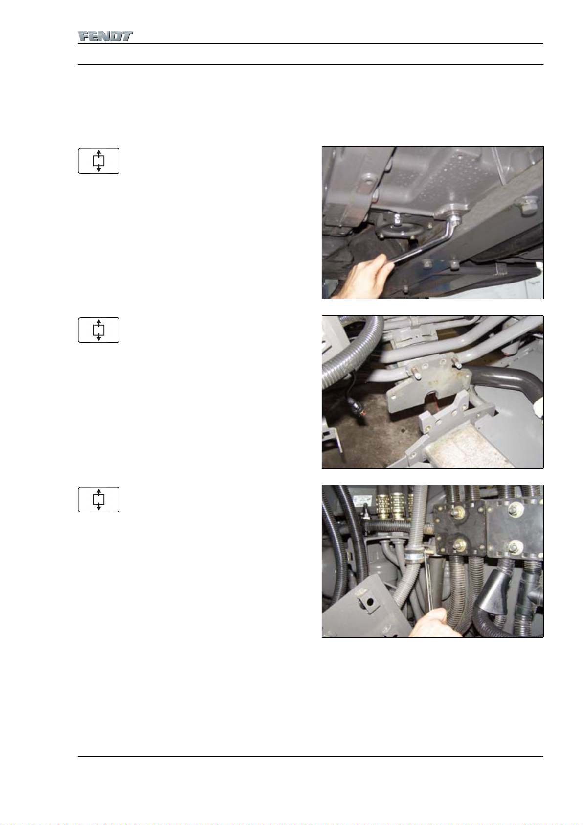
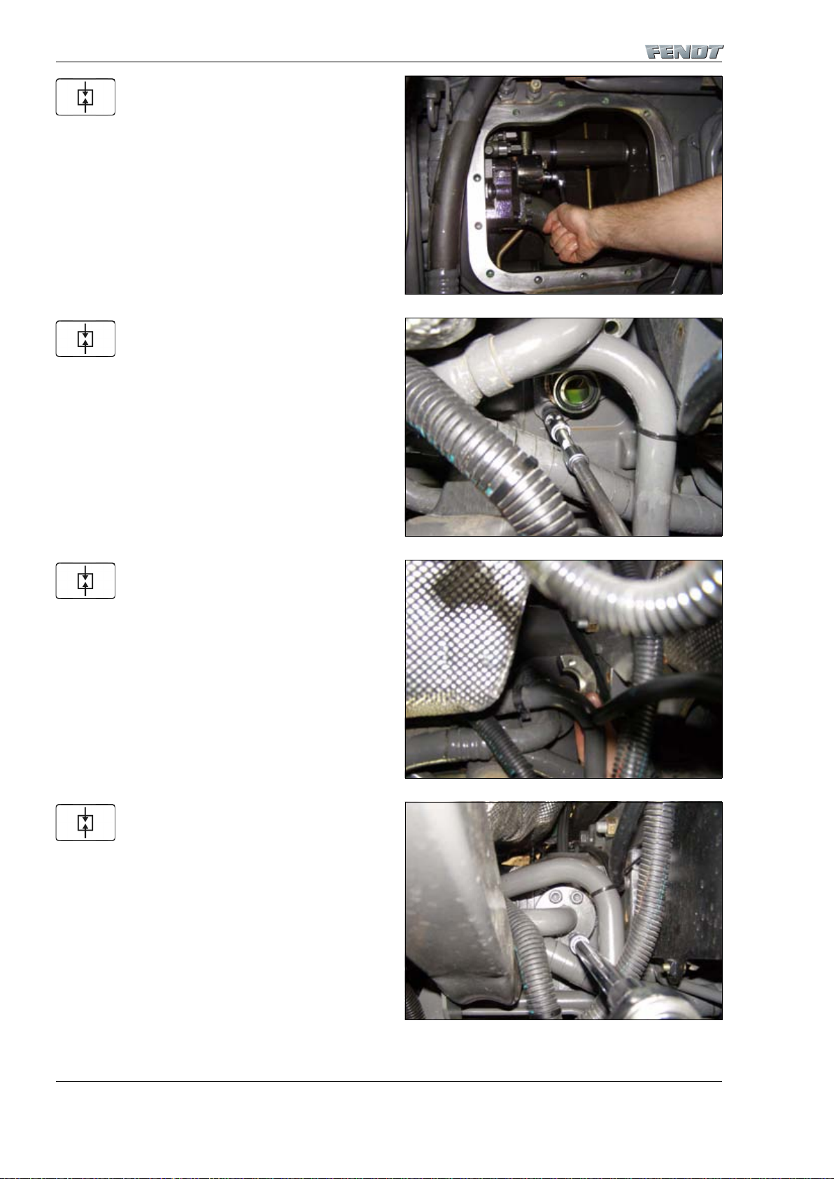
1 Removing the LS pump
Preliminary work:
– Drain fuel
– Remove battery
– Remove fuel tank, right
– Remove fuel hand pump and hydraulic hand pump
Drain hydraulic oil.
Loosen tank plate bolts and remove right tank plate.
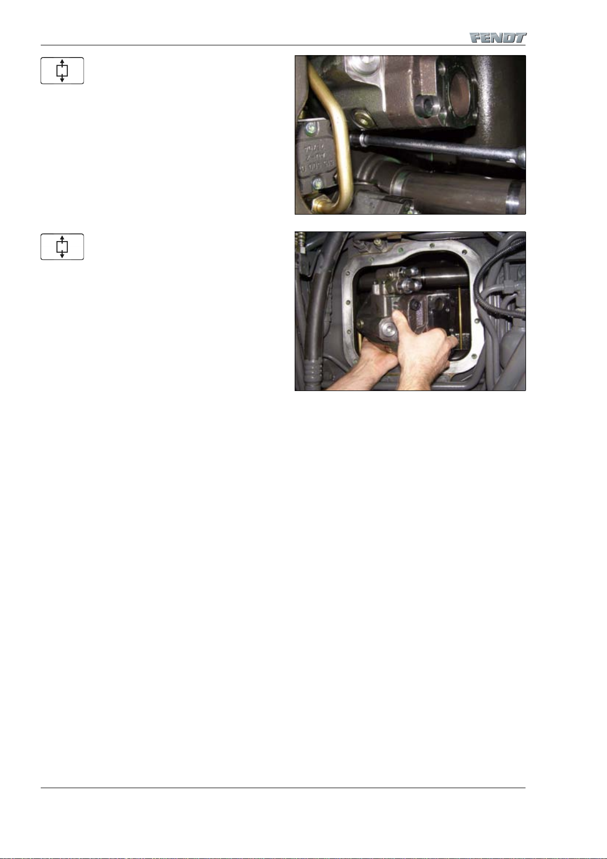
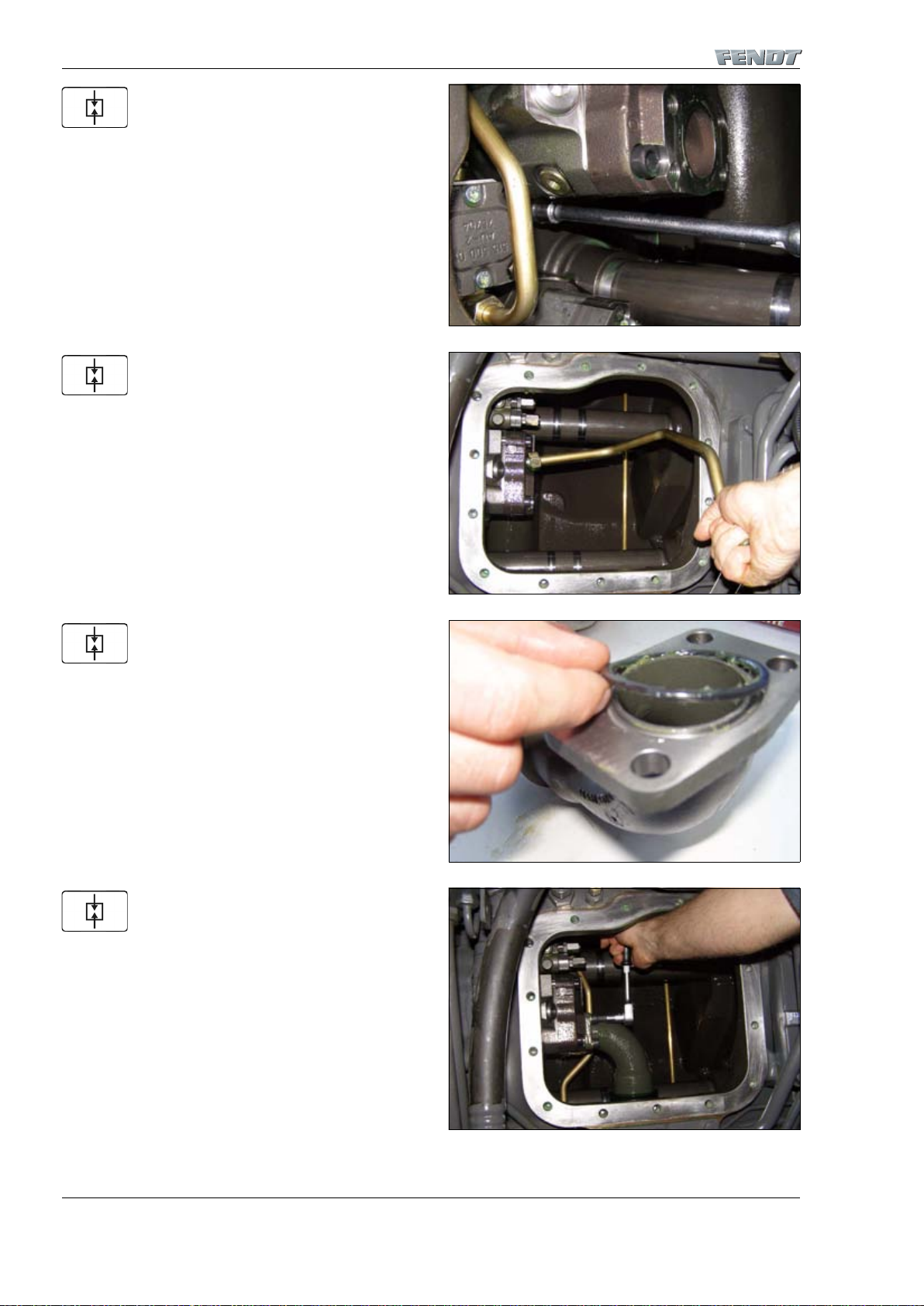
Remove cable clip.
I001690
Fig. 1.
I0 0170 7
Fig. 2.
I001688
Fig. 3.
Page 12
9410 - Hydraulic pump installation/LS pump
G - Repair
919 .. 0101-1000 925 .. 1001- 934 .. 0101-1000
919 .. 1001- 928 .. 0101-1000 934 .. 1001922 .. 0101-1000 928 .. 1001922 .. 1001- 931 .. 0101-1000
925 .. 0101-1000 931 .. 1001-
8
T000606
Version 1
22-06-2007
Loosen earth cable on engine.
Pull earth cable through to bracket.
Remove screws of bracket.
Fix cable bracket and cable in place so that cover is easily
accessible.
I001692
Fig. 4.
I001724
Fig. 5.
I001691
Fig. 6.
I001693
Fig. 7.
Page 13

919 .. 0101-1000 925 .. 1001- 934 .. 0101-1000
919 .. 1001- 928 .. 0101-1000 934 .. 1001922 .. 0101-1000 928 .. 1001922 .. 1001- 931 .. 0101-1000
925 .. 0101-1000 931 .. 1001-
9410 - Hydraulic pump installation/LS pump
G - Repair
9
T000606
Version 1
22-06-2007
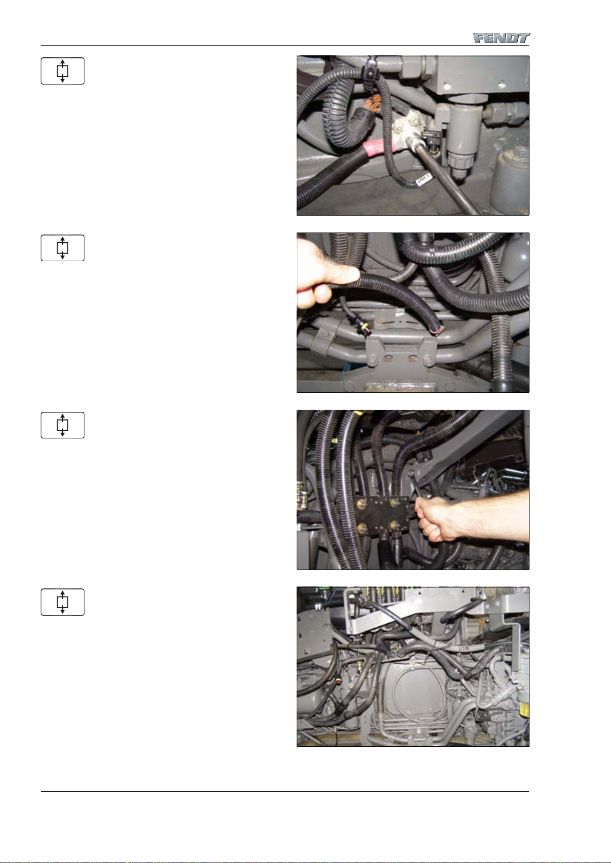
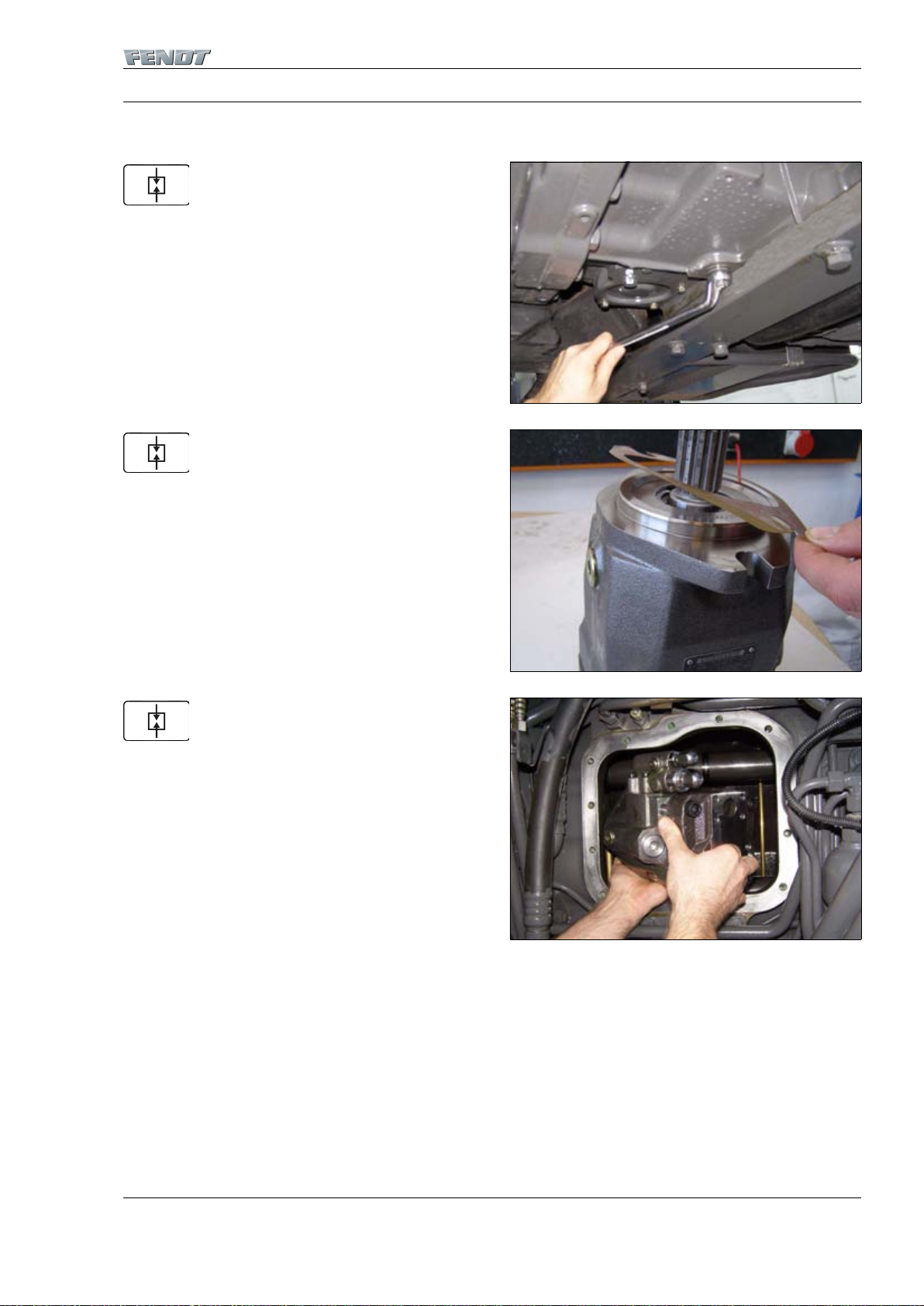
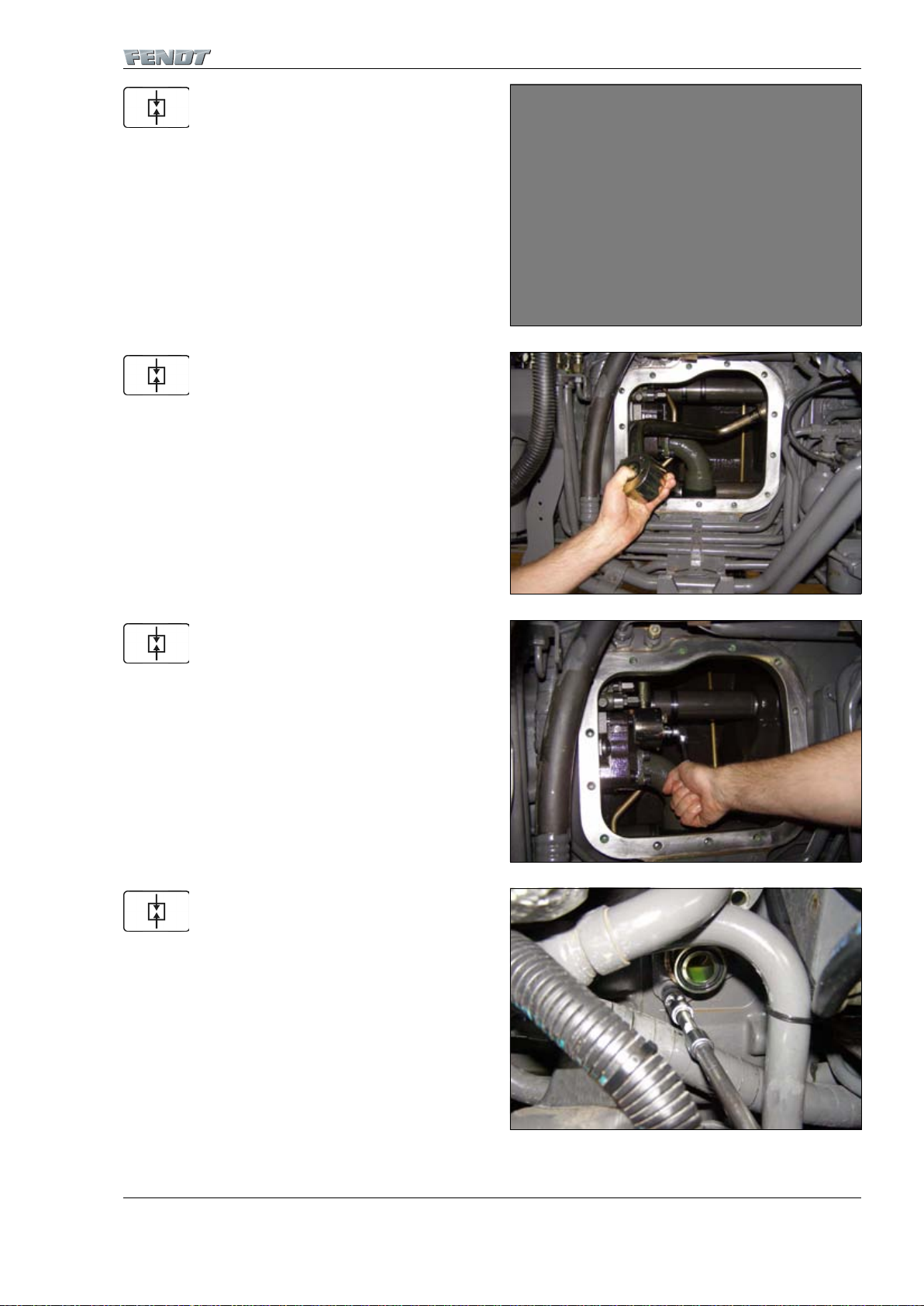
Separate LS line from housing and close lines, preventing
dirt from entering.
Loosen bolts of cover.
Remove cover of hydraulic oil tank.
Remove silencer from line flange.
I001689
Fig. 8.
I001694
Fig. 9.
I001695
Fig. 10.
I001696
Fig. 11.
Page 14
9410 - Hydraulic pump installation/LS pump
G - Repair
919 .. 0101-1000 925 .. 1001- 934 .. 0101-1000
919 .. 1001- 928 .. 0101-1000 934 .. 1001922 .. 0101-1000 928 .. 1001922 .. 1001- 931 .. 0101-1000
925 .. 0101-1000 931 .. 1001-
10
T000606
Version 1
22-06-2007
Loosen hexagon socket head screws from flange.
Hold on to crescent-shaped hardware when loosening
flange screws.
Fix pump hose in place on side.
Remove flange of pump line.
I001697
Fig. 12.
I001698
Fig. 13.
I001699
Fig. 14.
I001700
Fig. 15.
Page 15

919 .. 0101-1000 925 .. 1001- 934 .. 0101-1000
919 .. 1001- 928 .. 0101-1000 934 .. 1001922 .. 0101-1000 928 .. 1001922 .. 1001- 931 .. 0101-1000
925 .. 0101-1000 931 .. 1001-
9410 - Hydraulic pump installation/LS pump
G - Repair
11
T000606
Version 1
22-06-2007
Loosen screws of line flange.
Remove pump pressure line.
Remove pump intake line.
Remove hydraulic lines that are in the way when the
pump is removed.
I001701
Fig. 16.
I0 0170 2
Fig. 17.
I0 0170 3
Fig. 18.
I0 0170 4
Fig. 19.
Page 16
9410 - Hydraulic pump installation/LS pump
G - Repair
919 .. 0101-1000 925 .. 1001- 934 .. 0101-1000
919 .. 1001- 928 .. 0101-1000 934 .. 1001922 .. 0101-1000 928 .. 1001922 .. 1001- 931 .. 0101-1000
925 .. 0101-1000 931 .. 1001-
12
T000606
Version 1
22-06-2007
Remove bolts from LS pump.
Remove pump through opening.
NOTE: The pump is relatively heavy, so be careful when
you lift it out. Risk of injury!
I001705
Fig. 20.
I001706
Fig. 21.
Page 17
919 .. 0101-1000 925 .. 1001- 934 .. 0101-1000
919 .. 1001- 928 .. 0101-1000 934 .. 1001922 .. 0101-1000 928 .. 1001922 .. 1001- 931 .. 0101-1000
925 .. 0101-1000 931 .. 1001-
9410 - Hydraulic pump installation/LS pump
G - Repair
13
T000610
Version 1
22-06-2007
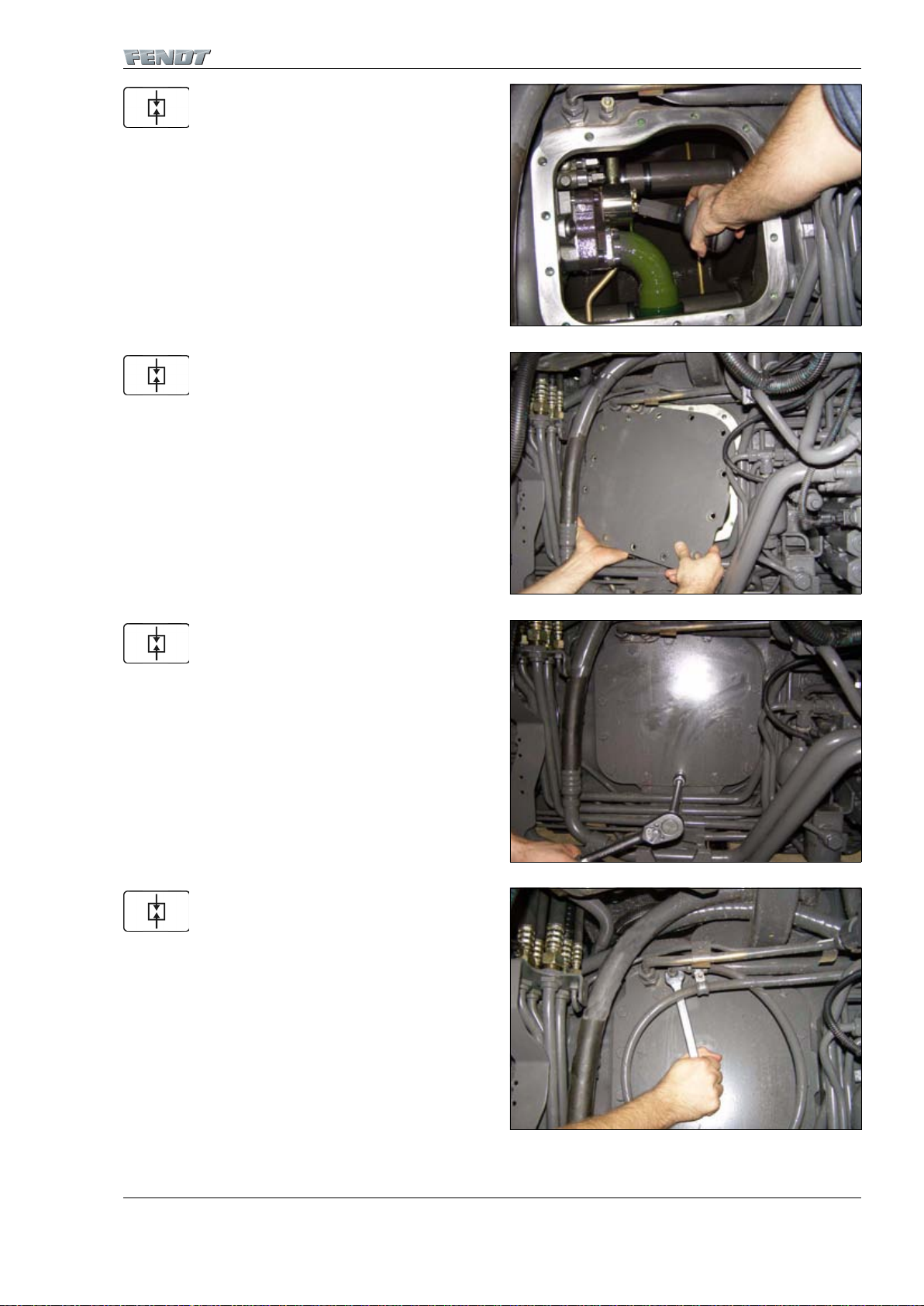
2 Installing the LS pump
Preliminary work:
– Clean sealing surfaces of hydraulic oil tank and hydraulic oil tank cover
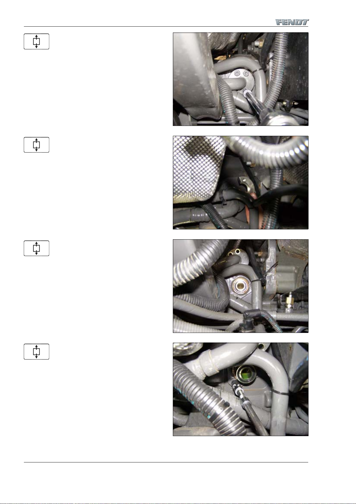
Mount oil drain plug with new seal ring.
Mount new pump flange seal.
Mount pump through opening.
I001690
Fig. 22.
I0 0170 8
Fig. 23.
I0 0170 6
Fig. 24.
Page 18
9410 - Hydraulic pump installation/LS pump
G - Repair
919 .. 0101-1000 925 .. 1001- 934 .. 0101-1000
919 .. 1001- 928 .. 0101-1000 934 .. 1001922 .. 0101-1000 928 .. 1001922 .. 1001- 931 .. 0101-1000
925 .. 0101-1000 931 .. 1001-
14
T000610
Version 1
22-06-2007
Tighten bolts of pump with a tightening torque of 85 Nm.
Mount removed hydraulic lines.
Insert new O-rings in the suction flange applying a little
grease.
Mount intake line with suction filter on pump.
I001705
Fig. 25.
I001704
Fig. 26.
I001710
Fig. 27.
I001703
Fig. 28.
Page 19
919 .. 0101-1000 925 .. 1001- 934 .. 0101-1000
919 .. 1001- 928 .. 0101-1000 934 .. 1001922 .. 0101-1000 928 .. 1001922 .. 1001- 931 .. 0101-1000
925 .. 0101-1000 931 .. 1001-
9410 - Hydraulic pump installation/LS pump
G - Repair
15
T000610
Version 1
22-06-2007
Insert new O-rings (arrowed) in pump line applying a little
grease.
Thread pump pressure line through opening.
Tighten screws of line flange by hand.
Centre flange on pump line to prevent causing strain and
tighten screws by hand.
I0 0170 9
Fig. 29.
I0 0170 2
Fig. 30.
I001701
Fig. 31.
I0 0170 0
Fig. 32.
Page 20
9410 - Hydraulic pump installation/LS pump
G - Repair
919 .. 0101-1000 925 .. 1001- 934 .. 0101-1000
919 .. 1001- 928 .. 0101-1000 934 .. 1001922 .. 0101-1000 928 .. 1001922 .. 1001- 931 .. 0101-1000
925 .. 0101-1000 931 .. 1001-
16
T000610
Version 1
22-06-2007
Slightly loosen screws of line flange to align it and then
tighten with the prescribed tightening torque.
Slightly loosen screws of flange to align it and then
tighten the screws.
Flange pump hose to pump line and fasten through crescent-shaped hardware.
Tighten hexagon socket head screws.
I0 01701
Fig. 33.
I001700
Fig. 34.
I001698
Fig. 35.
I001697
Fig. 36.
Page 21
919 .. 0101-1000 925 .. 1001- 934 .. 0101-1000
919 .. 1001- 928 .. 0101-1000 934 .. 1001922 .. 0101-1000 928 .. 1001922 .. 1001- 931 .. 0101-1000
925 .. 0101-1000 931 .. 1001-
9410 - Hydraulic pump installation/LS pump
G - Repair
17
T000610
Version 1
22-06-2007
Mount silencer.
Apply X903.050.074 sealant on sealing surfaces and
mount cover.
Tighten screws of tank cover with a tightening torque of
120 Nm
Mount LS line.
I001696
Fig. 37.
I001695
Fig. 38.
I001694
Fig. 39.
I001689
Fig. 40.
Page 22

9410 - Hydraulic pump installation/LS pump
G - Repair
919 .. 0101-1000 925 .. 1001- 934 .. 0101-1000
919 .. 1001- 928 .. 0101-1000 934 .. 1001922 .. 0101-1000 928 .. 1001922 .. 1001- 931 .. 0101-1000
925 .. 0101-1000 931 .. 1001-
18
T000610
Version 1
22-06-2007
Mount cable bracket.
Attach earth cable to engine earth pin.
Mount cable clip.
Mount tank plate with bolts.
Final procedures:
I001691
Fig. 41.
I001692
Fig. 42.
I001688
Fig. 43.
I001707
Fig. 44.
Page 23

919 .. 0101-1000 925 .. 1001- 934 .. 0101-1000
919 .. 1001- 928 .. 0101-1000 934 .. 1001922 .. 0101-1000 928 .. 1001922 .. 1001- 931 .. 0101-1000
925 .. 0101-1000 931 .. 1001-
9410 - Hydraulic pump installation/LS pump
G - Repair
19
T000610
Version 1
22-06-2007
– Mount fuel hand pump and hydraulic oil hand pump
– Fill up hydraulic oil (change hydraulic oil filter and hydraulic oil depending on hours and contamination)
– Mount fuel tank on right
– Mount battery
– Fill up fuel
Page 24

9410 - Hydraulic pump installation/LS pump
G - Repair
919 .. 0101-1000 925 .. 1001- 934 .. 0101-1000
919 .. 1001- 928 .. 0101-1000 934 .. 1001922 .. 0101-1000 928 .. 1001922 .. 1001- 931 .. 0101-1000
925 .. 0101-1000 931 .. 1001-
20
T000610
Version 1
22-06-2007
Page 25

A
General
9430
9430
B
Faults
Hydraulic pump installation/steering
pump
Hydraulic pump installation/steering pump
C
Documents and Diagrams
D
Component location
E
Testing
F
Setting and Calibration
G
Repair
H
Service – Info
Page 26

Page 27

9430 - Hydraulic pump installation/steering pump
Table of contents
3
9430 Hydraulic pump installation/steering pump
G Repair. . . . . . . . . . . . . . . . . . . . . . . . . . . . . . . . . . . . . .5
Page 28

9430 - Hydraulic pump installation/steering pump
Table of contents
4
Page 29

9430 - Hydraulic pump installation/steering pump
Table of contents
5
G Repair
1 Removing the wheel-driven emergency steering pump . . . . . . . . . . . . . . . . . . . . . . . . . . . 7
2 Installing the wheel-driven emergency steering pump . . . . . . . . . . . . . . . . . . . . . . . . . . . 11
Page 30

9430 - Hydraulic pump installation/steering pump
Table of contents
6
Page 31

919 .. 0101-1000 925 .. 1001- 934 .. 0101-1000
919 .. 1001- 928 .. 0101-1000 934 .. 1001922 .. 0101-1000 928 .. 1001922 .. 1001- 931 .. 0101-1000
925 .. 0101-1000 931 .. 1001-
9430 - Hydraulic pump installation/steering pump
G - Repair
7
T000613
Version 2
09-11-2007
1 Removing the wheel-driven emergency steering pump
Preliminary work:
– Drain fuel
– Remove fuel tank, right
– Remove battery
– Remove fuel hand pump and hydraulic hand pump
Drain hydraulic oil.
Drain transmission oil.
Loosen tank plate bolts and remove right tank plate.
I001690
Fig. 1.
I001718
Fig. 2.
I0 0170 7
Fig. 3.
Page 32

9430 - Hydraulic pump installation/steering pump
G - Repair
919 .. 0101-1000 925 .. 1001- 934 .. 0101-1000
919 .. 1001- 928 .. 0101-1000 934 .. 1001922 .. 0101-1000 928 .. 1001922 .. 1001- 931 .. 0101-1000
925 .. 0101-1000 931 .. 1001-
8
T000613
Version 2
09-11-2007
Remove cable clip.
Loosen earth cable on engine.
Pull earth cable through to bracket.
Remove cable bracket bolts.
I001688
Fig. 4.
I001692
Fig. 5.
I001724
Fig. 6.
I001691
Fig. 7.
Page 33

919 .. 0101-1000 925 .. 1001- 934 .. 0101-1000
919 .. 1001- 928 .. 0101-1000 934 .. 1001922 .. 0101-1000 928 .. 1001922 .. 1001- 931 .. 0101-1000
925 .. 0101-1000 931 .. 1001-
9430 - Hydraulic pump installation/steering pump
G - Repair
9
T000613
Version 2
09-11-2007
Fix cable bracket and cable in place so that cover is easily
accessible.
Separate LS line from housing and close lines, preventing
dirt from entering.
Loosen bolts of cover.
Remove cover.
I001693
Fig. 8.
I001689
Fig. 9.
I001694
Fig. 10.
I001695
Fig. 11.
Page 34

9430 - Hydraulic pump installation/steering pump
G - Repair
919 .. 0101-1000 925 .. 1001- 934 .. 0101-1000
919 .. 1001- 928 .. 0101-1000 934 .. 1001922 .. 0101-1000 928 .. 1001922 .. 1001- 931 .. 0101-1000
925 .. 0101-1000 931 .. 1001-
10
T000613
Version 2
09-11-2007
Remove intake line with suction filter of LS pump.
Remove pressure line from emergency steering pump.
Loosen emergency steering pump bolts.
Remove emergency steering pump through opening.
I001703
Fig. 12.
I0 01719
Fig. 13.
I001720
Fig. 14.
I001721
Fig. 15.
Page 35

919 .. 0101-1000 925 .. 1001- 934 .. 0101-1000
919 .. 1001- 928 .. 0101-1000 934 .. 1001922 .. 0101-1000 928 .. 1001922 .. 1001- 931 .. 0101-1000
925 .. 0101-1000 931 .. 1001-
9430 - Hydraulic pump installation/steering pump
G - Repair
11
T000614
Version 2
09-11-2007
2 Installing the wheel-driven emergency steering pump
Preliminary work:
– Clean sealing surfaces of housing and cover.
Insert new O-ring on emergency steering pump applying
a little grease.
Mount emergency steering pump.
Tighten bolt with a tightening torque of 70 Nm.
I0 0172 2
Fig. 16.
I0 0172 1
Fig. 17.
I0 0172 0
Fig. 18.
Page 36

9430 - Hydraulic pump installation/steering pump
G - Repair
919 .. 0101-1000 925 .. 1001- 934 .. 0101-1000
919 .. 1001- 928 .. 0101-1000 934 .. 1001922 .. 0101-1000 928 .. 1001922 .. 1001- 931 .. 0101-1000
925 .. 0101-1000 931 .. 1001-
12
T000614
Version 2
09-11-2007
Mount pressure line of emergency steering pump.
Mount intake line with suction filter of LS pump.
Apply X903.050.074 sealant on sealing surfaces and
mount cover.
Tighten screws of tank cover with a tightening torque of
120 Nm
I0 01719
Fig. 19.
I001703
Fig. 20.
I001695
Fig. 21.
I001694
Fig. 22.
Page 37

919 .. 0101-1000 925 .. 1001- 934 .. 0101-1000
919 .. 1001- 928 .. 0101-1000 934 .. 1001922 .. 0101-1000 928 .. 1001922 .. 1001- 931 .. 0101-1000
925 .. 0101-1000 931 .. 1001-
9430 - Hydraulic pump installation/steering pump
G - Repair
13
T000614
Version 2
09-11-2007
Mount LS line.
Mount cable bracket.
Attach earth cable to engine earth pin.
Mount cable clip.
I001689
Fig. 23.
I001691
Fig. 24.
I001692
Fig. 25.
I001688
Fig. 26.
Page 38

9430 - Hydraulic pump installation/steering pump
G - Repair
919 .. 0101-1000 925 .. 1001- 934 .. 0101-1000
919 .. 1001- 928 .. 0101-1000 934 .. 1001922 .. 0101-1000 928 .. 1001922 .. 1001- 931 .. 0101-1000
925 .. 0101-1000 931 .. 1001-
14
T000614
Version 2
09-11-2007
Mount tank plate with bolts.
Mount hydraulic oil drain plug with new seal ring.
Tighten transmission oil drain plug.
Final procedures:
– Mount fuel hand pump and hydraulic oil hand pump
– Fill up hydraulic oil (change hydraulic oil filter and hydraulic oil depending on hours and contamination)
– Fill up transmission oil (change transmission oil filter and transmission oil depending on hours and contamination)
– Mount fuel tank on right
– Reconnect battery
– Fill up fuel
I001707
Fig. 27.
I001690
Fig. 28.
I001718
Fig. 29.
Page 39

A
General
9534
9534
B
Faults Hydraulic piping/"Rüfa"reverse operation
Hydraulic piping/"Rüfa"reverse operation
C
Documents and Diagrams
D
Component location
E
Testing
F
Setting and Calibration
G
Repair
H
Service – Info
Page 40

Page 41

9534 - Hydraulic piping/"Rüfa"reverse operation
Table of contents
3
9534 Hydraulic piping/"Rüfa"reverse operation
C Documents and diagrams . . . . . . . . . . . . . . . . . . . . . .5
G Repair. . . . . . . . . . . . . . . . . . . . . . . . . . . . . . . . . . . . .13
Page 42

9534 - Hydraulic piping/"Rüfa"reverse operation
Table of contents
4
Page 43

9534 - Hydraulic piping/"Rüfa"reverse operation
Table of contents
5
C Documents and diagrams
1 Technical drawing of rotary feedthrough (Rüfa) . . . . . . . . . . . . . . . . . . . . . . . . . . . . . . . . . . 7
Page 44

9534 - Hydraulic piping/"Rüfa"reverse operation
Table of contents
6
Page 45

919 .. 0101-1000 925 .. 1001- 934 .. 0101-1000
919 .. 1001- 928 .. 0101-1000 934 .. 1001922 .. 0101-1000 928 .. 1001922 .. 1001- 931 .. 0101-1000
925 .. 0101-1000 931 .. 1001-
9534 - Hydraulic piping/"Rüfa"reverse operation
C - Documents and diagrams
7
T001352
Version 1
21-04-2009
1 Technical drawing of rotary feedthrough (Rüfa)
I003770
Fig. 1.
Item Designation Item Designation
1 Washer 13 Rotor (not available individually)
2 Bearing 15 Ring (not available individually)
3 Hex screw 16 Shim (not available individually)
4 Spring washer 18 Seal set
6 Carrier 21 Thread insert (not available individually)
7 Pressure hose 22 Socket head cap screw
10 Rotary feedthrough (complete) 23 Seal ring
11 Stator (not available individually) 24 Hex screw
12 Stator (not available individually) 25 Spring washer
Page 46

9534 - Hydraulic piping/"Rüfa"reverse operation
C - Documents and diagrams
919 .. 0101-1000 925 .. 1001- 934 .. 0101-1000
919 .. 1001- 928 .. 0101-1000 934 .. 1001922 .. 0101-1000 928 .. 1001922 .. 1001- 931 .. 0101-1000
925 .. 0101-1000 931 .. 1001-
8
T001352
Version 1
21-04-2009
Cross-section of rotary feedthrough
I003767
Fig. 2.
Page 47

919 .. 0101-1000 925 .. 1001- 934 .. 0101-1000
919 .. 1001- 928 .. 0101-1000 934 .. 1001922 .. 0101-1000 928 .. 1001922 .. 1001- 931 .. 0101-1000
925 .. 0101-1000 931 .. 1001-
9534 - Hydraulic piping/"Rüfa"reverse operation
C - Documents and diagrams
9
T001352
Version 1
21-04-2009
Underside view
A.) Ensure the correct positioning of the bores on the carrier ring rotor during installation.
I003768
Fig. 3.
Page 48

9534 - Hydraulic piping/"Rüfa"reverse operation
C - Documents and diagrams
919 .. 0101-1000 925 .. 1001- 934 .. 0101-1000
919 .. 1001- 928 .. 0101-1000 934 .. 1001922 .. 0101-1000 928 .. 1001922 .. 1001- 931 .. 0101-1000
925 .. 0101-1000 931 .. 1001-
10
T001352
Version 1
21-04-2009
Top view
I003769
Fig. 4.
Page 49

919 .. 0101-1000 925 .. 1001- 934 .. 0101-1000
919 .. 1001- 928 .. 0101-1000 934 .. 1001922 .. 0101-1000 928 .. 1001922 .. 1001- 931 .. 0101-1000
925 .. 0101-1000 931 .. 1001-
9534 - Hydraulic piping/"Rüfa"reverse operation
C - Documents and diagrams
11
T001352
Version 1
21-04-2009
Ports on the rotary feedthrough
Piping for the rotary feedthrough (rotor)
Serial
No.
NW Ports Max.
pressure
Max. flow rate Medium Function
Rotor Stator (bar) (l/min)
1 6 M16 x 1.5 M16 x 1.5 8.5 - Compressed air Hand brake
2 6 M16 x 1.5 M16 x 1.5 8.5 - Compressed air Hand brake
3 6 M16 x 1.5 M16 x 1.5 8.5 - Compressed air Hand brake
4 8 M14 x 1.5 M16 x 1.5 8.5 - Compressed air Tank, right
5 8 M14 x 1.5 M16 x 1.5 8.5 - Compressed air Brake, front axle
6 8 M14 x 1.5 M16 x 1.5 8.5 Compressed air Brake, rear axle
7 8 M14 x 1.5 M16 x 1.5 8.5 - Compressed air Tank, l e f t
8 Internal connection channel with 14 - - 9 6 M12 x 1.5 M12 x 1.5 210 1 Hydraulic oil Load sensing (LS)
10 6 M12 x 1.5 M12 x 1.5 30 3 Pentosin
(X902.011.622)
Clutch
11 12 M18 x 1.5 M18 x 1.5 210 50 Hydraulic oil Pump pressure
(p)
12 12 M18 x 1.5 M18 x 1.5 210 50 Hydraulic oil Steering, right
13 12 M18 x 1.5 M18 x 1.5 210 50 Hydraulic oil Steering, left
14 12 M18 x 1.5 M18 x 1.5 3 5 Hydraulic oil Return (R)
15 8 M14 x 1.5 - - - Air Outlet air, hand-
brake
16 8 M16 x 1.5 - - - Air Outlet air, hand-
brake
I003771
Fig. 5.
Page 50

9534 - Hydraulic piping/"Rüfa"reverse operation
C - Documents and diagrams
919 .. 0101-1000 925 .. 1001- 934 .. 0101-1000
919 .. 1001- 928 .. 0101-1000 934 .. 1001922 .. 0101-1000 928 .. 1001922 .. 1001- 931 .. 0101-1000
925 .. 0101-1000 931 .. 1001-
12
T001352
Version 1
21-04-2009
Piping for the rotary feedthrough (stator)
I003772
Fig. 6.
Page 51

919 .. 0101-1000 925 .. 1001- 934 .. 0101-1000
919 .. 1001- 928 .. 0101-1000 934 .. 1001922 .. 0101-1000 928 .. 1001922 .. 1001- 931 .. 0101-1000
925 .. 0101-1000 931 .. 1001-
9534 - Hydraulic piping/"Rüfa"reverse operation
Table of contents
13
G Repair
1 Sealing the rotary feedthrough. . . . . . . . . . . . . . . . . . . . . . . . . . . . . . . . . . . . . . . . . . . . . . 15
Page 52

9534 - Hydraulic piping/"Rüfa"reverse operation
Table of contents
919 .. 0101-1000 925 .. 1001- 934 .. 0101-1000
919 .. 1001- 928 .. 0101-1000 934 .. 1001922 .. 0101-1000 928 .. 1001922 .. 1001- 931 .. 0101-1000
925 .. 0101-1000 931 .. 1001-
14
Page 53

919 .. 0101-1000 925 .. 1001- 934 .. 0101-1000
919 .. 1001- 928 .. 0101-1000 934 .. 1001922 .. 0101-1000 928 .. 1001922 .. 1001- 931 .. 0101-1000
925 .. 0101-1000 931 .. 1001-
9534 - Hydraulic piping/"Rüfa"reverse operation
G - Repair
15
T002984
Version 1
21-04-2009
1 Sealing the rotary feedthrough
Loosen cap screws (22) by about three turns
I007993
Fig. 1.
Item Designation Item Designation
1 Washer 13 Rotor (not available individually)
2 Bearing 15 Ring (not available individually)
3 Hex screw 16 Shim (not available individually)
4 Spring washer 18 Seal set
6 Carrier 21 Thread insert (not available individually)
7 Pressure hose 22 Socket head cap screw
10 Rotary feedthrough (complete) 23 Seal ring
11 Stator (not available individually) 24 Hex screw
12 Stator (not available individually) 25 Spring washer
I007965
Fig. 2.
Page 54

9534 - Hydraulic piping/"Rüfa"reverse operation
G - Repair
919 .. 0101-1000 925 .. 1001- 934 .. 0101-1000
919 .. 1001- 928 .. 0101-1000 934 .. 1001922 .. 0101-1000 928 .. 1001922 .. 1001- 931 .. 0101-1000
925 .. 0101-1000 931 .. 1001-
16
T002984
Version 1
21-04-2009
Place wood underneath the three lugs, so that there is a
gap between the working surface and the front end of the
rotary feedthrough; using a rubber mallet, tap the screw
head thus moving stator (11) downwards and then remove cap screws (22)
Turn rotary feedthrough and remove hex bolts (24)
Disassemble stator (11) and ring (15) using a mounting lever
Remove stator (11) and ring (15)
I007966
Fig. 3.
I007968
Fig. 4.
I007967
Fig. 5.
I007969
Fig. 6.
Page 55

919 .. 0101-1000 925 .. 1001- 934 .. 0101-1000
919 .. 1001- 928 .. 0101-1000 934 .. 1001922 .. 0101-1000 928 .. 1001922 .. 1001- 931 .. 0101-1000
925 .. 0101-1000 931 .. 1001-
9534 - Hydraulic piping/"Rüfa"reverse operation
G - Repair
17
T002984
Version 1
21-04-2009
Disassemble ring (16)
Push rotor (13) out of stator (12), use the 3 lugs on stator
(12) as a supporting surface
Hold rotor (13) while pushing it out
Take the seal ring and O-ring out of rotor (13)
NOTE: A bent welding wire can be used as an aid here
I007970
Fig. 7.
I007971
Fig. 8.
I007972
Fig. 9.
I007973
Fig. 10.
Page 56

9534 - Hydraulic piping/"Rüfa"reverse operation
G - Repair
919 .. 0101-1000 925 .. 1001- 934 .. 0101-1000
919 .. 1001- 928 .. 0101-1000 934 .. 1001922 .. 0101-1000 928 .. 1001922 .. 1001- 931 .. 0101-1000
925 .. 0101-1000 931 .. 1001-
18
T002984
Version 1
21-04-2009
Take the seal ring and O-ring out of stator (12)
NOTE: A bent welding wire can be used as an aid here
NOTE: Check all surfaces and grooves for damage and wear
Lightly spray all seals with oil
Fit O-rings in stator (12)
Fit seal rings in stator (12), while pressing the seal ring in
a crescent shape
I007974
Fig. 11.
I007977
Fig. 12.
I007976
Fig. 13.
I007980
Fig. 14.
Page 57

919 .. 0101-1000 925 .. 1001- 934 .. 0101-1000
919 .. 1001- 928 .. 0101-1000 934 .. 1001922 .. 0101-1000 928 .. 1001922 .. 1001- 931 .. 0101-1000
925 .. 0101-1000 931 .. 1001-
9534 - Hydraulic piping/"Rüfa"reverse operation
G - Repair
19
T002984
Version 1
21-04-2009
Fit O-rings in rotor (13)
Fit seal rings in rotor (13), while pressing the seal ring in a
crescent shape
Lubricate the sealing washer and place on stator (12)
Insert rotor (13) in stator (12)
I007981
Fig. 15.
I007982
Fig. 16.
I007975
Fig. 17.
I007983
Fig. 18.
Page 58

9534 - Hydraulic piping/"Rüfa"reverse operation
G - Repair
919 .. 0101-1000 925 .. 1001- 934 .. 0101-1000
919 .. 1001- 928 .. 0101-1000 934 .. 1001922 .. 0101-1000 928 .. 1001922 .. 1001- 931 .. 0101-1000
925 .. 0101-1000 931 .. 1001-
20
T002984
Version 1
21-04-2009
Push rotor (13) into stator (12)
Mount ring (15) using hex bolts (24), turn rotor (13) such
that the bore (arrow) of the rotor and of the ring are directly above one another
Lubricate the sealing washer and fit to stator (11)
Press in stator (11)
I007989
Fig. 19.
I007984
Fig. 20.
I007985
Fig. 21.
I007990
Fig. 22.
Page 59

919 .. 0101-1000 925 .. 1001- 934 .. 0101-1000
919 .. 1001- 928 .. 0101-1000 934 .. 1001922 .. 0101-1000 928 .. 1001922 .. 1001- 931 .. 0101-1000
925 .. 0101-1000 931 .. 1001-
9534 - Hydraulic piping/"Rüfa"reverse operation
G - Repair
21
T002984
Version 1
21-04-2009
Lubricate the sealing washer and place on washer (16)
Fit washer (16)
Fit cap screws with seal ring (22, 23)
Tightening torque: 9 Nm
Check for leaks: Charge every port on the rotary
feedthrough in succession with compressed air (own provision), close each outlet and then listen and feel whether
air is escaping from a different outlet
NOTE: see §1
I007986
Fig. 23.
I007988
Fig. 24.
I007965
Fig. 25.
I007987
Fig. 26.
Page 60

9534 - Hydraulic piping/"Rüfa"reverse operation
G - Repair
919 .. 0101-1000 925 .. 1001- 934 .. 0101-1000
919 .. 1001- 928 .. 0101-1000 934 .. 1001922 .. 0101-1000 928 .. 1001922 .. 1001- 931 .. 0101-1000
925 .. 0101-1000 931 .. 1001-
22
T002984
Version 1
21-04-2009
Page 61

A
General
9600
9600
B
Faults Overall system/hydraulic equipment
Overall system/hydraulic equipment
C
Documents and Diagrams
D
Component location
E
Testing
F
Setting and Calibration
G
Repair
H
Service – Info
Page 62

Page 63

9600 - Overall system/hydraulic equipment
Table of contents
3
9600 Overall system/hydraulic equipment
A General. . . . . . . . . . . . . . . . . . . . . . . . . . . . . . . . . . . . .5
C Documents and diagrams . . . . . . . . . . . . . . . . . . . . .17
E Measuring and testing . . . . . . . . . . . . . . . . . . . . . . . .25
Page 64

9600 - Overall system/hydraulic equipment
Table of contents
4
Page 65

9600 - Overall system/hydraulic equipment
Table of contents
5
A General
1 Pressure regulation – PR (LS pump). . . . . . . . . . . . . . . . . . . . . . . . . . . . . . . . . . . . . . . . . . . 7
2 Hydraulic comparison: FENDT 900 COM III to FENDT 900 COM II. . . . . . . . . . . . . . . . . . 10
3 Technical specification: working and steering hydraulics. . . . . . . . . . . . . . . . . . . . . . . . . . 11
4 Overview of pressure measuring points . . . . . . . . . . . . . . . . . . . . . . . . . . . . . . . . . . . . . . 13
5 External pressure rise (Power Beyond) . . . . . . . . . . . . . . . . . . . . . . . . . . . . . . . . . . . . . . . 15
Page 66

9600 - Overall system/hydraulic equipment
Table of contents
6
Page 67

919 .. 0101-1000 925 .. 1001- 934 .. 0101-1000
919 .. 1001- 928 .. 0101-1000 934 .. 1001922 .. 0101-1000 928 .. 1001922 .. 1001- 931 .. 0101-1000
925 .. 0101-1000 931 .. 1001-
9600 - Overall system/hydraulic equipment
A - General
7
T000448
Version 2
07-11-2007
1 Pressure regulation – PR (LS pump)
The LS pump is not driven
The variable displacement piston (1) is brought into contact with the "Q max. stop" by spring force and the pump is stationary in maximum swivel angle position (max. volume flow 163 l/min or 215 l/min).
At the same time, the spring pushes the pressure cut-off valve (2) into the position shown.
The large variable displacement piston chamber is connected to the tank connection via the control line.
The stationary pump is not supplying any oil, so no pressure builds up.
The pump is driven at a constant speed.
The pump generates a volume flow from the suction point to the consumer.
Pressure rises in the high-pressure pipe according to the load resistance of the consumer.
At the same time, this working pressure acts on the measuring surface of the control valve (2).
As long as the working pressure does not reach the set value (Pmax), the force of the spring prevails over the control
piston of the control valve (2).
The control piston remains in its position, and the pump remains in maximum swivel angle position accordingly (Q max).
The consumer is moved at maximum speed.
I001331
Fig. 1.
Page 68

9600 - Overall system/hydraulic equipment
A - General
919 .. 0101-1000 925 .. 1001- 934 .. 0101-1000
919 .. 1001- 928 .. 0101-1000 934 .. 1001922 .. 0101-1000 928 .. 1001922 .. 1001- 931 .. 0101-1000
925 .. 0101-1000 931 .. 1001-
8
T000448
Version 2
07-11-2007
As the working pressure increases, the pressure on the measuring surface of the control valve (2) increases accordingly.
The hydraulic force prevails over the set spring force, and the control valve (2) moves to the right and opens the valve.
The pressure in the large variable displacement chamber of the variable displacement piston (1) increases.
If this pressure increases to exceed the counter pressure built up by the spring force and the pressure in the small chamber, the variable displacement piston moves to the left.
This process denotes the start of control.
A further increase in working pressure creates a larger opening of the control valve (2) and increased pressure in the large
variable displacement chamber (1).
The pump swivels towards zero (Q min) and keeps the working pressure at a constant.
Absolute zero is not reached by this swivel process; "zero" position means that no axial piston movement takes place and
therefore oil is no longer supplied.
However, there may be internal leaking, at the pump itself and at the stationary consumer and the valves.
The pump needs to compensate for this to maintain the pressure.
The pump provides a permanent supply of oil to do this.
The pump remains in a "quasi-zero position".
I001332
Fig. 2.
Page 69

919 .. 0101-1000 925 .. 1001- 934 .. 0101-1000
919 .. 1001- 928 .. 0101-1000 934 .. 1001922 .. 0101-1000 928 .. 1001922 .. 1001- 931 .. 0101-1000
925 .. 0101-1000 931 .. 1001-
9600 - Overall system/hydraulic equipment
A - General
9
T000448
Version 2
07-11-2007
The working pressure at the pressure connection falls (e.g. by actuating a directional control valve).
The pressure on the measuring surface of the control valve (2) falls under the spring pressure and the control piston is
moved to the left by the spring force.
The large variable displacement chamber (1) is relieved by the control line to the tank.
The spring force causes the variable displacement piston to swivel out, thus reaching the axial piston pump.
The maximum volume flow (Q max) of the pump is available for the directional control valve.
I001333
Fig. 3.
Page 70

9600 - Overall system/hydraulic equipment
A - General
919 .. 0101-1000 925 .. 1001- 934 .. 0101-1000
919 .. 1001- 928 .. 0101-1000 934 .. 1001922 .. 0101-1000 928 .. 1001922 .. 1001- 931 .. 0101-1000
925 .. 0101-1000 931 .. 1001-
10
T000446
Version 3
31-10-2008
2 Hydraulic comparison: FENDT 900 COM III to FENDT 900 COM II
Summary and comparison of hydraulic systems
Component FENDT 900 COM III FENDT 900 COM II
LS pump Inclined disc axial-flow piston pump
with pressure and flow rate control
Inclined disc axial-flow piston pump
with pressure and flow rate control
Minimum standby pressure (valves
locked)
22 bar 22 bar
Minimum standby pressure (valves
unlocked)
22 bar 42 to 45 bar
Flow rate 163 l/min (optional 215 l/min) 110 l/min (163 l/min, optional from
10/2 004)
Pump drive 1¼ inch 1 inch from 10/2004 (previously 7/8
inch)
Control pressure differential 20 bar 20 bar
Max. working pressure 200 bar 200 bar
Control pressure 23 bar from the auxiliary pump 23 bar from the LS pump
Auxiliary pump Gear pump Gear pump
Flow rate 22.5 cc/r - 55l/min --->
1-circuit brake system without front
PTO
11 cc/r - 34 l/min
22.5 cc/r + 8 cc/r --->
1-circuit brake system with front PTO
22.5 cc/r + 16 cc/r --->
2-circuit brake system
Connection condition When the pilot pressure is released
or the LS pump is exhausted
LS pump exhausted or steering sluggish
Max. pressure 200 bar 190 bar
Wheel-driven emergency steering
pump
Wheel-driven gear pump ----------
Flow rate 8 cc/r ----------
Control valves SB 23 LS-EHS 2 SB 23 LS-EHS
Max. flow rate 100 l/min (optional 140 l/min - only
Pos. 4 possible)
80 l/min
Measuring and testing - pressure
measuring points
M1 Emergency steering pump pressure
(wheel-driven)
Not present
M2 Auxiliary pump pressure Auxiliary pump pressure
M3 LS pump pressure LS pump pressure
M4 LS pressure LS pressure
M5 Control pressure Control pressure
Page 71

919 .. 0101-1000 925 .. 1001- 934 .. 0101-1000
919 .. 1001- 928 .. 0101-1000 934 .. 1001922 .. 0101-1000 928 .. 1001922 .. 1001- 931 .. 0101-1000
925 .. 0101-1000 931 .. 1001-
9600 - Overall system/hydraulic equipment
A - General
11
T000320
Version 3
05-10-2009
3 Technical specification: working and steering hydraulics
Component Specifications
Working and steering hydraulics Load sensing hydraulics
LS pump PR Inclined disc axial flow piston pump
with pressure and flow rate regulation
Pump (series): flow rate at
rated engine speed = 2200 rpm
163 l/min
Pump (optional): flow rate at
rated engine speed = 2200 rpm
215 l/min
Max. working pressure 200 bar
Control pressure differential 20 bar
Transmission ratio (diesel engine: pump) 0.869
Auxiliary pump PH Gear pump
Flow rate/revolution for
1-circuit braking system without front PTO
22.5 cc/rev. – single pump
Flow rate/revolution for
1-circuit braking system with front PTO
22.5 cc/rev + 8 cc/rev tandem pump
at 25 bar DBV
Flow rate/revolution for
2-circuit braking system with/without front PTO
22.5 cc/rev + 16 cc/rev tandem pump
at 25 bar DBV
Transmission ratio (diesel engine: pump) 0.896
Flow rate at
rated engine speed = 2200 rpm
55 l/min
Max. pressure 190 bar
Drive Flange-mounted to air compressor
Emergency steering pump PNL 8 cc wheel-driven gear pump
Flow rate at 60 km/h 36 l/min
Flow rate at 10 km/h 6 l/min
Drive via 4WD
Auxiliary control valves SB 23 LS-EHS 2
Max. flow rate 100 l/min (optional 140 l/min - only Pos. 4 possible)
Auxiliary control valves (standard) 4 valves, rear:
1.1 "yellow", 1.2 "blue", 1.3 "red", 1.4 "green"
Auxiliary control valves (optional) Max. 6 valves, rear: 1.5 "brown", 1.6 "purple"
+ 2 valves, front: 2.1 "olive", 2.2 "grey"
Actuation system Electro-hydraulic via CAN bus (daisy chain)
Rear power lift (Power) EPC 23 C - SA
Rear power lift (Professional) EPC 23 C - SA/DA
Front power lift (Standard) Hydac valve SA
Front power lift (Enhanced control) EPC 23 C - SA/DA
Hydraulic trailer brake valve Optional
Page 72

9600 - Overall system/hydraulic equipment
A - General
919 .. 0101-1000 925 .. 1001- 934 .. 0101-1000
919 .. 1001- 928 .. 0101-1000 934 .. 1001922 .. 0101-1000 928 .. 1001922 .. 1001- 931 .. 0101-1000
925 .. 0101-1000 931 .. 1001-
12
T000320
Version 3
05-10-2009
1.1 Yellow valve (standard)
1.2 Blue valve (standard)
1.3 Red valve (standard)
1.4 Green valve (standard)
1.5 Brown valve
1.6 Violet valve
CD Overflow oil line (Case Drain)
Hy. ABV Hydraulic trailer brake valve
LS LS control line (load sensing)
P Pump pressure line
RH Return line, rear
2.1 Olive valve
2.2 Grey valve
RF Return line, front
I004435
Fig. 4.
I000956
Fig. 5.
Page 73

919 .. 0101-1000 925 .. 1001- 934 .. 0101-1000
919 .. 1001- 928 .. 0101-1000 934 .. 1001922 .. 0101-1000 928 .. 1001922 .. 1001- 931 .. 0101-1000
925 .. 0101-1000 931 .. 1001-
9600 - Overall system/hydraulic equipment
A - General
13
T000392
Version 3
05-10-2009
4 Overview of pressure measuring points
M1 Measuring point, emergency steering
pump
M2 Measuring point, auxiliary pump
M3 Measuring point, LS pump
M4 Measuring point, LS pressure
M5 Measuring point, control pressure
M6 Rear return flow reference pressure mea-
suring point
I001210
Fig. 6.
M1 pPNL Emergency steering pump pressure
- Since it is flange-mounted to the 4WD, the pump operates only during travel
M2 pPH - Auxiliary pump pressure
- Standby pressure for control pressure
- As needed and at a steering lock of 190 bar
(Need scenario exists only if the LS pump is fully "occupied" with current oil demand, can no
longer meet demand, and pressure requirement from steering system is higher than current
working pressure)
M3 pPR All LS pump pressures
- Min. standby pressure
- Current working pressure
- Max. standby pressure
Other functions (engine speed/cold-start/warm-start) are also active when engine is started.
M4 pLS Control pressure (=command/signal) to the LS pump
M5 pSt Control pressure is required to activate control valves 1…8 and also for the EPC valves
I005866
Fig. 7.
M6 RREF rear Pressure in the rear return flow
- is measured in the rear end plate
Page 74

9600 - Overall system/hydraulic equipment
A - General
919 .. 0101-1000 925 .. 1001- 934 .. 0101-1000
919 .. 1001- 928 .. 0101-1000 934 .. 1001922 .. 0101-1000 928 .. 1001922 .. 1001- 931 .. 0101-1000
925 .. 0101-1000 931 .. 1001-
14
T000392
Version 3
05-10-2009
M7 Front return flow reference pressure mea-
suring point
I005867
Fig. 8.
M7 RREF front Pressure in the front return flow
- is measured in the middle end plate
Page 75

919 .. 0101-1000 925 .. 1001- 934 .. 0101-1000
919 .. 1001- 928 .. 0101-1000 934 .. 1001922 .. 0101-1000 928 .. 1001922 .. 1001- 931 .. 0101-1000
925 .. 0101-1000 931 .. 1001-
9600 - Overall system/hydraulic equipment
A - General
15
T000457
Version 2
31-10-2008
5 External pressure rise (Power Beyond)
Implements with hydraulic consumers that are operated on the tractor often have very long supply lines, which pose the
risk of pressure loss. Hence, the 22 bar of control pressure is not always reached.
The control pressure increase is set and activated via the terminal. This in turn energises the pressure cut-off valve, external LS, reinforcement (DRVE), in dependence of the set value. The wider the pressure cut-off valve opens, the higher
the volume of oil fed by the pressure line (P) to the LS line, which raises the LS pressure.
If additional pressure is present in the external LS line, the control line pressure pushes the pressure cut-off valve further
to the right and the LS pressure is raised.
The flow cut-off valve, external LS relief (SRVE) is required to allow a small volume of oil to flow to the tank (T), thus
relieving the LS line.
The pressure filter, external LS (DFE) protects the system from impurities that penetrate the system via the external LS
line.
I002113
Fig. 9.
Item Designation Item Designation
PR LS pump p Pump pressure
Y084 Control pressure increase solenoid valve
(DRVE)
R Return flow
DFF Pressure filter LS Load sensing pressure
LS ext External load sensing connection M3 Measuring point: pump pressure p
SRVE Flow cut-off valve, external load sensing relief M4 Measuring point: load sensing pressure LS
Page 76

9600 - Overall system/hydraulic equipment
A - General
919 .. 0101-1000 925 .. 1001- 934 .. 0101-1000
919 .. 1001- 928 .. 0101-1000 934 .. 1001922 .. 0101-1000 928 .. 1001922 .. 1001- 931 .. 0101-1000
925 .. 0101-1000 931 .. 1001-
16
T000457
Version 2
31-10-2008
Page 77

919 .. 0101-1000 925 .. 1001- 934 .. 0101-1000
919 .. 1001- 928 .. 0101-1000 934 .. 1001922 .. 0101-1000 928 .. 1001922 .. 1001- 931 .. 0101-1000
925 .. 0101-1000 931 .. 1001-
9600 - Overall system/hydraulic equipment
Table of contents
17
C Documents and diagrams
1 Hydraulic circuit diagram with legend . . . . . . . . . . . . . . . . . . . . . . . . . . . . . . . . . . . . . . . . 19
Page 78

9600 - Overall system/hydraulic equipment
Table of contents
919 .. 0101-1000 925 .. 1001- 934 .. 0101-1000
919 .. 1001- 928 .. 0101-1000 934 .. 1001922 .. 0101-1000 928 .. 1001922 .. 1001- 931 .. 0101-1000
925 .. 0101-1000 931 .. 1001-
18
Page 79

919 .. 0101-1000 925 .. 1001- 934 .. 0101-1000
919 .. 1001- 928 .. 0101-1000 934 .. 1001922 .. 0101-1000 928 .. 1001922 .. 1001- 931 .. 0101-1000
925 .. 0101-1000 931 .. 1001-
9600 - Overall system/hydraulic equipment
C - Documents and diagrams
19
T000318
Version 2
04-09-2009
1 Hydraulic circuit diagram with legend
Item Designation DIN Item Designation DIN
APE - Entry plate for external pressure supply MVKFS [Y022] - Lowering solenoid valve
(standard front power lift)
Y022
ASP1 - Accumulator, suspension 1 MVKH [Y055] - Rear pressure compensator
lock valve (SA/DA)
ASP2 - Accumulator, suspension 2 MVL [Y012] - Solenoid valve, charge function
(suspension, oil pre-heater)
Y012
AVF 1 - Lock valve, suspension 1 MVP [Y032] - Solenoid valve, pilot pressure Y032
AVF 2 - Lock valve, suspension 2 MVUL [Y082] - Solenoid valve, lower link stabi-
liser lock
Y082
BF - Ventilation filter MVVH [Y060] - Solenoid valve, rear pre-heater Y060
DBV1 - Main pressure-limiting valve MVVM [Y061] - Solenoid valve, central pre-
heater
Y061
DBVF1 - Pressure-limiting valve, suspension 1 OETR - Oil temperature regulator
DBVF2 - Pressure-limiting valve, suspension 2 PH - Auxiliary pump
DBVKF [Y022] - Field pressure valve, DA front
power lift enhanced control
PNL - Emergency steering pump
DBVKH [Y062] - Field pressure valve, DA rear
power lift
PR - LS pump
DBV-L - Pressure-limiting valve, 175 bar steer-
ing
PVL - Priority valve, steering
DFE - Pressure filter, external LS RLF - Return line filter
DFP - Pressure filter, pilot pressure RVF1 - Non-return valve, suspension 1
DFWH - Flow monitor, auxiliary pump RVFH - Non-return valve, raise suspension
DRVE [Y084] - Pressure cut-off valve, Power
Beyond
RVFS - Non-return valve, lower suspension
DRVF [Y013] - Suspension load pressure/lower RVL1-3 - Non-return valve, steering 1-3
DRVP - Pressure cut-off valve, pilot pressure RVN - Non-return valve, emergency steering
pump
DS1 - Pressure switch, LS pump monitor SFH - Auxiliary pump suction filter
DSF [B063] - Pressure switch, filter monitor B063 SFN1+2 - Suction filter, emergency steering
pump 1+2
DWKF - Pressure compensator, front power
lift, SA
SFR - Suction filter, LS pump
DWL - Pressure compensator, steering SRVE - Flow cut-off valve, external LS relief
DWP - Pressure compensator, pilot pressure SVUL [Y083] - Solenoid valve, lower link stabi-
liser release
Y083
EPH - End plate, rear valve block TG [B013] - Temperature sensor B013
EPM - End plate, centre VBF - Valve block, suspension
FKH - Front power lift VBL - Valve block, steering
FSP - Front power lift accumulator VBP - Valve block, pilot pressure supply
FSS [B084] - Level switch B084 WV1 - LS shuttle valve 1
GDR - Silencer, LS pump WVP - Shuttle valve, pilot pressure
HKH - Rear power lift ZF1 - Federungszylinder 1
HP - Hand pump, pilot pressure – emergency
supply
ZL - Steering cylinder
Hy.ABV - Hydraulic trailer brake ZSB - Central control block
Page 80

9600 - Overall system/hydraulic equipment
C - Documents and diagrams
919 .. 0101-1000 925 .. 1001- 934 .. 0101-1000
919 .. 1001- 928 .. 0101-1000 934 .. 1001922 .. 0101-1000 928 .. 1001922 .. 1001- 931 .. 0101-1000
925 .. 0101-1000 931 .. 1001-
20
T000318
Version 2
04-09-2009
K - Hydraulic oil cooler ZSP - Auxiliary accumulator, suspension
LE - Steering unit Autoguide
M1 - Measuring point, emergency pumps APLE - Connection plate for el.-hyd. steering
system
M2 - Measuring point, auxiliary pumps DRVLE - Pilot pressure cut-off valve, el.-hyd.
steering system
M3 - Measuring point, LS pump MVLE1 [Y085] - Solenoid valve, pilot pres-
sure/switch-off (Auto-Guide)
M4 - Measuring point, LS pressure MVLE2 [Y086] - Solenoid valve, steering dis-
connect (Auto-Guide)
M5 - Measuring point, control pressure PVLE - Proportional valve, el.-hyd. steering sys-
tem
MVFF [Y067] - Solenoid valve, lock suspension Y067 VBLE1 - Valve block, el.-hyd. steering system 1
MVFH [Y065] - Solenoid valve, raise suspen-
sion
Y065 VBLE2 - Valve block, el.-hyd. steering system 2
MVFW [Y063] - Solenoid valve, wobble stabiliser
Y063 VLE1 - LE priority valve (oversteering valve)
MVKF [Y021] - Front pressure compensator
lock valve (SA/DA)
Y021 VLE2+3 - LE switch off 1 + 2 valves
MVKFH [Y021] - Lifting solenoid valve (standard front power lift)
Y021 WVLE - LS shuttle valve, el.-hyd. steering sys-
tem
Item Designation DIN Item Designation DIN
Page 81

919 .. 0101-1000 925 .. 1001- 934 .. 0101-1000
919 .. 1001- 928 .. 0101-1000 934 .. 1001-
922 .. 0101-1000 928 .. 1001-
922 .. 1001- 931 .. 0101-1000
925 .. 0101-1000 931 .. 1001-
9600 - Overall system/hydraulic equipment
C - Documents and diagrams
21
T000318
Version 2
04-09-2009
I000962
Fig. 1. Pumps
Page 82

9600 - Overall system/hydraulic equipment
C - Documents and diagrams
919 .. 0101-1000 925 .. 1001- 934 .. 0101-1000
919 .. 1001- 928 .. 0101-1000 934 .. 1001922 .. 0101-1000 928 .. 1001922 .. 1001- 931 .. 0101-1000
925 .. 0101-1000 931 .. 1001-
22
T000318
Version 2
04-09-2009
I000937
Fig. 2. Central control block and steering
Page 83

919 .. 0101-1000 925 .. 1001- 934 .. 0101-1000
919 .. 1001- 928 .. 0101-1000 934 .. 1001922 .. 0101-1000 928 .. 1001922 .. 1001- 931 .. 0101-1000
925 .. 0101-1000 931 .. 1001-
9600 - Overall system/hydraulic equipment
C - Documents and diagrams
23
T000318
Version 2
04-09-2009
I000968
Fig. 3. Rear valve block
Page 84

9600 - Overall system/hydraulic equipment
C - Documents and diagrams
919 .. 0101-1000 925 .. 1001- 934 .. 0101-1000
919 .. 1001- 928 .. 0101-1000 934 .. 1001922 .. 0101-1000 928 .. 1001922 .. 1001- 931 .. 0101-1000
925 .. 0101-1000 931 .. 1001-
24
T000318
Version 2
04-09-2009
I000969
Fig. 4. Central valve block
Page 85

919 .. 0101-1000 925 .. 1001- 934 .. 0101-1000
919 .. 1001- 928 .. 0101-1000 934 .. 1001922 .. 0101-1000 928 .. 1001922 .. 1001- 931 .. 0101-1000
925 .. 0101-1000 931 .. 1001-
9600 - Overall system/hydraulic equipment
Table of contents
25
E Measuring and testing
1 Test report, fax template . . . . . . . . . . . . . . . . . . . . . . . . . . . . . . . . . . . . . . . . . . . . . . . . . . 27
Page 86

9600 - Overall system/hydraulic equipment
Table of contents
919 .. 0101-1000 925 .. 1001- 934 .. 0101-1000
919 .. 1001- 928 .. 0101-1000 934 .. 1001922 .. 0101-1000 928 .. 1001922 .. 1001- 931 .. 0101-1000
925 .. 0101-1000 931 .. 1001-
26
Page 87

919 .. 0101-1000 925 .. 1001- 934 .. 0101-1000
919 .. 1001- 928 .. 0101-1000 934 .. 1001922 .. 0101-1000 928 .. 1001922 .. 1001- 931 .. 0101-1000
925 .. 0101-1000 931 .. 1001-
9600 - Overall system/hydraulic equipment
E - Measuring and testing
27
T000371
Version 4
05-10-2009
1 Test report, fax template
Pressure testing
NOTE: Initial condition of tractor for all measurements:
– Engine in idle (800 rpm)
– Valves and EPC are locked
– No steering
– In tractors with hydraulic trailer brakes, release the pressure with the trailer brake button while the handbrake is ap-
plied
– Oil temperature 40-50°C
FENDT Measurement no.
Chassis no.: Op. hrs. reading: Keyword: Name: Date:
LS pump test
[PR]
M2
(bar)
M3
(bar)
M4
(bar)
M5
(bar)
Oil tem-
perature
A SETPOINT
ACTUAL
SETPOINT
ACTUAL
SETPOINT
ACTUAL
SETPOINT
ACTUAL
A1 Minimum standby pressure
(Valves locked)
12-18 20-24 0 0
A2 Minimum standby pressure
(Valves unlocked)
34-40 20-24 0 22-25
A3 Free steering when stationary
To left/right
(Valves unlocked)
34-40
/
Depending
on resis-
tance
/
Depending
on resis-
tance
/
22-25
A4 Turn steering to stop
To left/right
(Valves unlocked)
34-40
/
195-200
/
170-180
/
22-25
A5 Yellow control valve
Raise/lower
34-40
/
198-210
/
198-210
/
22-25
A6 Blue control valve
Raise/lower
34-40
/
198-210
/
198-210
/
22-25
A7 Red control valve
Raise/lower
34-40
/
198-210
/
198-210
/
22-25
A8 Green control valve
Raise/lower
34-40
/
198-210
/
198-210
/
22-25
A9 Brown control valve
Raise/lower
34-40
/
198-210
/
198-210
/
22-25
A10 Violet control valve
Raise/lower
34-40
/
198-210
/
198-210
/
22-25
A11 Olive control valve
Raise/lower
34-40
/
198-210
/
198-210
/
22-25
A12 Grey control valve
Raise/lower
34-40
/
198-210
/
198-210
/
22-25
A13 Rear EPC with external
pushbutton to stop
34-40 198-210 198-210 22-25
A14 Front power lift with external
pushbutton to stop
34-40 198-210 198-210 22-25
A15 Suspension ON or during
raising
(Valves unlocked)
34-40 198-210 198-210 22-25
Page 88

9600 - Overall system/hydraulic equipment
E - Measuring and testing
919 .. 0101-1000 925 .. 1001- 934 .. 0101-1000
919 .. 1001- 928 .. 0101-1000 934 .. 1001922 .. 0101-1000 928 .. 1001922 .. 1001- 931 .. 0101-1000
925 .. 0101-1000 931 .. 1001-
28
T000371
Version 4
05-10-2009
Auxiliary pump test
[PH]
M2
(bar)
M3
(bar)
M4
(bar)
M5
(bar)
Oil tem-
perature
B Connect the short circuit hose to a con-
trol valve and
use the terminal to set the valve to
max. flow rate and
deflect or
– Short circuit hose from pressure con-
nection, external to return line, rear
SETPOINT
ACTUAL
SETPOINT
ACTUAL
SETPOINT
ACTUAL
SETPOINT
ACTUAL
B1 Free steering when stationary
(Valves unlocked)
Depending
on resis-
tance
Depending
on resis-
tance
Depending
on resis-
tance
22-25
B2 Steering at stop to
left/right
(Valves unlocked)
190 - 200 Depending
on resis-
tance
175 - 185 22-25
B3
Wheel-driven steering pump test M1
(bar)
M1
(bar)
Oil temperature
C [PNL]
- only when driving forwards
SETPOINT ACTUAL
C1 10 k m/h 0.4
C2 40 km/h 1. 5
C3
Further measurements M1
(bar)
M2
(bar)
M3
(bar)
M4
(bar)
M5
(bar)
Oil tem-
perature
D special conditions/combina-
tions/sequences/settings/imple-
ments
SET-
POINT
ACTUAL
SET-
POINT
ACTUAL
SET-
POINT
ACTUAL
SET-
POINT
ACTUAL
SET-
POINT
ACTUAL
D1
D2
D3
D4
Page 89

919 .. 0101-1000 925 .. 1001- 934 .. 0101-1000
919 .. 1001- 928 .. 0101-1000 934 .. 1001922 .. 0101-1000 928 .. 1001922 .. 1001- 931 .. 0101-1000
925 .. 0101-1000 931 .. 1001-
9600 - Overall system/hydraulic equipment
E - Measuring and testing
29
T000371
Version 4
05-10-2009
Measuring leak oil volume at LS pump
NOTE: Do not perform measurement, unless:
– There are genuine doubts about the pump volume
– The overall hydraulic function has already been checked
Preparation:
Direct the leak oil line of the LS pump into a receptacle with a litre scale.
Starting condition of tractor
– Oil temperature 50°C
– With a maximum standby pressure of 200 bar and zero delivery
– Engine speed 1500 rpm
Pump status Leak oil
New Approx. 5 l/min
Permissible, normal state Up to 12 l/min
Worn From 12 l/min
Page 90

9600 - Overall system/hydraulic equipment
E - Measuring and testing
919 .. 0101-1000 925 .. 1001- 934 .. 0101-1000
919 .. 1001- 928 .. 0101-1000 934 .. 1001922 .. 0101-1000 928 .. 1001922 .. 1001- 931 .. 0101-1000
925 .. 0101-1000 931 .. 1001-
30
T000371
Version 4
05-10-2009
Page 91

A
General
9605
9605
B
Faults
Hydraulic equipment/hydraulic connec-
tions
Hydraulic equipment/hydraulic connections
C
Documents and Diagrams
D
Component location
E
Testing
F
Setting and Calibration
G
Repair
H
Service – Info
Page 92

Page 93

9605 - Hydraulic equipment/hydraulic connections
Table of contents
3
9605 Hydraulic equipment/hydraulic connections
G Repair. . . . . . . . . . . . . . . . . . . . . . . . . . . . . . . . . . . . . .5
Page 94

9605 - Hydraulic equipment/hydraulic connections
Table of contents
4
Page 95

9605 - Hydraulic equipment/hydraulic connections
Table of contents
5
G Repair
1 Removing rear hydraulic quick-release coupler . . . . . . . . . . . . . . . . . . . . . . . . . . . . . . . . . . 7
2 Installing rear hydraulic quick-release coupler . . . . . . . . . . . . . . . . . . . . . . . . . . . . . . . . . . 10
Page 96

9605 - Hydraulic equipment/hydraulic connections
Table of contents
6
Page 97

919 .. 0101-1000 925 .. 1001- 934 .. 0101-1000
919 .. 1001- 928 .. 0101-1000 934 .. 1001922 .. 0101-1000 928 .. 1001922 .. 1001- 931 .. 0101-1000
925 .. 0101-1000 931 .. 1001-
9605 - Hydraulic equipment/hydraulic connections
G - Repair
7
T000621
Version 1
22-06-2007
1 Removing rear hydraulic quick-release coupler
NOTE: The coupler housing does not have to be removed if only the quick-release coupling inserts are removed.
For greater clarity, the work was performed with the control valve removed.
Loosen coupler housing bolts and remove housing (when
the control valve is installed, a long Allen key is required).
Remove protective cap of coupler.
Remove circlip from coupler insert.
I001740
Fig. 1.
I001741
Fig. 2.
I001742
Fig. 3.
Page 98

9605 - Hydraulic equipment/hydraulic connections
G - Repair
919 .. 0101-1000 925 .. 1001- 934 .. 0101-1000
919 .. 1001- 928 .. 0101-1000 934 .. 1001922 .. 0101-1000 928 .. 1001922 .. 1001- 931 .. 0101-1000
925 .. 0101-1000 931 .. 1001-
8
T000621
Version 1
22-06-2007
Operate release lever to push out and remove coupler.
Remove pressure sleeve with circlip pliers.
Remove circlip from release lever.
Remove release lever.
I0 01743
Fig. 4.
I0 01744
Fig. 5.
I0 01745
Fig. 6.
I0 01746
Fig. 7.
Page 99

919 .. 0101-1000 925 .. 1001- 934 .. 0101-1000
919 .. 1001- 928 .. 0101-1000 934 .. 1001922 .. 0101-1000 928 .. 1001922 .. 1001- 931 .. 0101-1000
925 .. 0101-1000 931 .. 1001-
9605 - Hydraulic equipment/hydraulic connections
G - Repair
9
T000621
Version 1
22-06-2007
Remove plastic cover and pressure lever.
I001747
Fig. 8.
Page 100

9605 - Hydraulic equipment/hydraulic connections
G - Repair
919 .. 0101-1000 925 .. 1001- 934 .. 0101-1000
919 .. 1001- 928 .. 0101-1000 934 .. 1001922 .. 0101-1000 928 .. 1001922 .. 1001- 931 .. 0101-1000
925 .. 0101-1000 931 .. 1001-
10
T000622
Version 1
22-06-2007
2 Installing rear hydraulic quick-release coupler
Prepare cleaned parts of hydraulic coupler for assembly.
Insert new support rings and O-rings.
Insert release rocker in coupler housing, ensure that the
marking points to the release lever.
Insert release lever in bore.
I0 01748
Fig. 9.
I0 01749
Fig. 10.
I0 01747
Fig. 11.
I0 01746
Fig. 12.
 Loading...