

Page 1
Service Training
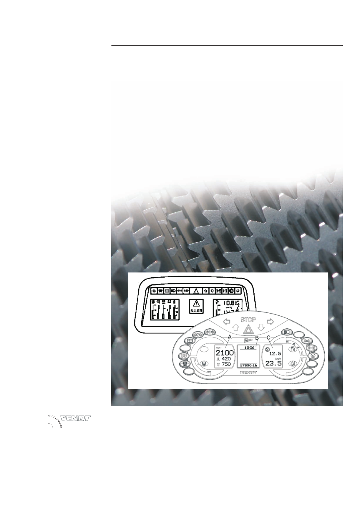
Vario tractors - fault code tables
Edition
09/2007
Service-Training
Dokumentation
X990.005.448.012 - Englisch
PSD - 3289 G - en
AGCO GmbH
Johann-Georg-Fendt-Str. 4 D-87616 Marktoberdorf
Farmer 400
Favorit 700
Favorit 900
FENDT 700 Vario
FENDT 800 Vario
FENDT 900 Vario
FENDT 300 Vario (COM III)
FENDT 400 Vario (COM III)
FENDT 700 Vario (COM III)
FENDT 800 Vario (COM III)
FENDT 900 Vario (COM III)
Page 2

All relevant accident prevention regulations and all generally accepted safety, health and
road traffic regulations must be strictly observed. The manufacturer does not accept liability
for damage resulting from unauthorised modifications.
AGCO GmbH
87616 Marktoberdorf
Tel.: (08342) 77 - 0 Fax: (08342) 77 -222
Page 3

FENDT 409
Vario 409 .. / 1001-
FENDT 410
FENDT 411
FENDT 412
FENDT 711
FENDT 712
FENDT 714
FENDT 716
FENDT 815
FENDT 817
FENDT 818
FENDT 916
Vario 410 .. / 1001-
Vario 411 .. / 1001-
Vario 412 .. / 1001-
Vario 711 .. / 1001-
Vario 712 .. / 1001-
Vario 714 .. / 1001-
Vario 716 .. / 1001-
Vario 715 .. / 1001-
Vario 717 .. / 1001-
Vario 718 .. / 1001-
Vario 916 .. / 1001-
FENDT Vario (COM I / COM II)
FENDT 920
FENDT 924
FENDT 926
FENDT 930
Vario 920 .. / 1001-
Vario 924 .. / 1001-
Vario 926 .. / 1001-
Vario 930 .. / 1001-
Fault code table
Fault code table
Tableau de codes défauts
Tableau de codes défauts
Tabella codici disturbi
Tabella codici disturbi
Tabla códiga averías
Tabla códiga averías
Storingscodetabel
StörcodetabelleStörcodetabelle
Storingscodetabel
410 .. 1001- / 411 .. 1001- / 412 .. 1001- * 711 .. 1001- / 712 .. 1001- / 714 .. 1001- / 716 .. 1001-
.. 1001- / 717 .. 1001- / 718 .. 1001- * 916 .. 1001- / 920 .. 1001- / 924 .. 1001- / 926 .. 1001- / 930 .. 1001-
409 .. 1001- /
715
Page 4

Page 5

all Vario tractors
Tractor / General system
Vario Tractors - Fault Codes
B
Faults
12/1999
0000 000001
B
f
1/58
Capitel Docu-No.
Index
Date Version
Page
Vario Tractors - Fault Codes
FCT_InitPage
Fault
code
Id code Brief description Description Consequences Link FENDIAS / Note
0.0.11 A021;
A022
ECU, EDC;
ECU, EMR
EDC / EMR bus fault.
Fault in ECU
Tractor can be driven
using accelerator.
Programming errors in
ECU.
Fault message, no
restrictions.
EOL reprogramming
necessary.
0.0.12 A008 Vario terminal Bus fault No functions available,
no display
Power supply for CAN
bus is in circuit board
A013; fuse F039, F046
0.0.13 A004 Control console Bus fault No functions available,
no display
Power supply for CAN
bus is in circuit board
A013; fuse F040, F041
0.0.14 A009 Transmission control
unit
Bus fault No functions available,
no display
Power supply for CAN
bus is in circuit board
A013; fuse F040, F041
0.0.15 A001,
A002
4WD engagement;
Diff. lock engagement
Bus fault No functions available,
no display
Power supply for CAN
bus is in circuit board
A013; fuses F040, F041
0.0.16 A001,
A002
Rear PTO Bus fault No functions available,
no display
Power supply for CAN
bus is in circuit board
A013; fuses F040, F041
0.0.17 A001,
A002
Front PTO Bus fault No functions available,
no display
Power supply for CAN
bus is in circuit board
A013; fuses F040, F041
0.0.18 A005,
A014
Rear EPC Bus fault No functions available,
no display
Power supply for CAN
bus is in circuit board
A013; fuses F040, F041
0.0.19 A002 Front power lift Bus fault No functions available,
no display
See Service Training
EPC C
(X990.005.023.026en)
Page 6
all Vario tractors
Tractor / General system
Vario Tractors - Fault Codes
B
Faults
12/1999
0000 000001
B
f
2/58
Capitel Docu-No.Index
Date Version
Page
Vario Tractors - Fault Codes
0.0.1A A002,
Y015,
Y016,
Y017,
Y018,
Y019
ECU, enhanced control,
electric auxiliary control
valves
Bus fault No functions available,
no display
Power supply for CAN
bus is in circuit board
A013; fuses F040, F041
0.0.1B A002 ECU, enhanced control TeachIn bus faulty -
Master (Variotronic TI)
('Teach-in data transfer
fault')
Emergency mode
0.0.1E ECU, Neumaier Bus fault Neumaier
reversing system
Neumaier System
doesn't work
(Neumaier Service
Manual)
0.0.1F A034 Joystick Joystick bus fault ('Drive
switch data transfer
fault')
Emergency operation,
no auxiliary valve
operation
Power supply for CAN
bus is in circuit board
A013; fuse F047
JOYSTICK CAN JOYSTICK
0.0.20 A007 Instrument cluster CAN Bus fault between
A007 instrument cluster
and tractor electronics
No functions available,
no display
Power supply for CAN
bus is in circuit board
A013; fuses F040, F041
0.1.50 A007 Instrument cluster VDO instrument cluster
EEPROM not
programmed
Malfunctions in
instrument cluster
EOL reprogramming
necessary
0.1.51 B012 Engine oil pressure
sensor
Sensor fault, wiring fault No monitoring 'Instrument cluster'
circuit diagram
12 V supply fault A013 fuse 24
0.1.54 B019 Compressed air tank
pressure sensor
Sensor fault, wiring fault No display 'Instrument cluster'
circuit diagram
12 V supply fault A013 fuse 25
0.1.55 S036 Hydraulic oil level
sensor
Sensor fault, wiring fault No monitoring 'Spool valves 1' circuit
diagram
0.1.56 B005,
A021,
A022
Temperature sensor
engine temp. (=water),
(ECU,EDC / EMR)
Sensor fault, wiring fault No monitoring 'Instrument cluster'
circuit diagram
Fault
code
Id code Brief description Description Consequences Link FENDIAS / Note
Page 7

all Vario tractors
Tractor / General system
Vario Tractors - Fault Codes
B
Faults
12/1999
0000 000001
B
f
3/58
Capitel Docu-No.
Index
Date Version
Page
Vario Tractors - Fault Codes
0.1.57 B006,
A022
Sensor, charge air
temperature,
ECU, EMR
Sensor fault, wiring fault No monitoring Circuit diagram:
"Instrument cluster"
(F400, F700); "EDC
control" (F900); "EMR
engine control (F7/800
Vario)
For EDC/EMR EDC level converter /
SERDIA diagnostics
0.1.59 B007;
B034
Fuel level sensor Sensor fault, wiring fault No display 'Instrument cluster'
circuit diagram
1.1.01,
poss.
B038
or
B055
EDC / EMR foot throttle
rotary position sensor
(yellow), combi-sensor
Signal too high, signal
too low, signal missing
for longer than 2000 ms
Chapter 2000 Reg.B
(EDC fault or EMR fault)
'EDC Engine control',
'EMR Engine control'
circuit diagram
TRANSMISSION,
AUTOMATIC MAXIMUM
OUTPUT CONTROL
1.1.03 B029,
B038
or
B055
EST foot throttle rotary
position sensor EST
(red), EDC foot throttle
rotary position sensor
(yellow), combi-sensor
B029 and B038 do not
match, no match B055 combi-sensor (PIN 3 to
PIN 6)
Restricted operating
mode, Chapter 2000
Reg.B (EDC fault or
EMR fault)
'EDC Engine control',
'EMR Engine control'
circuit diagram
TRANSMISSION,
AUTOMATIC MAXIMUM
OUTPUT CONTROL,
calibration code '4005'
1.1.04 A002 ECU, enhanced control Tractor Management
System (TMS)
checksum error
Tractor Management
System (TMS) doesn't
function
EOL reprogramming
necessary
1.1.05 A021;
A022
EDC control module Engine configuration
could not be read from
the EDC / EMR - control
unit
TMS is disengaged 'EDC Engine control',
'EMR Engine control'
circuit diagram
1.1.7E B035 Hand throttle rotary
position sensor
Signal out of range Restricted operating
mode, Chapter 2000
Reg.B (EDC fault or
EMR fault)
'EDC Engine control',
'EMR Engine control'
circuit diagram
TRANSMISSION,
AUTOMATIC MAXIMUM
OUTPUT CONTROL
8.5 V supply fault Fuse 26
1.1.7F A004 Control console Electrical fault in hand
throttle memory keys
(EDC/EMR). No
communication with
control console.
Last speed setting is
retained. Engine speed
can be changed using
hand throttle or
accelerator.
JOYSTICK, CANJOYSTICK
Fault
code
Id code Brief description Description Consequences Link FENDIAS / Note
Page 8

all Vario tractors
Tractor / General system
Vario Tractors - Fault Codes
B
Faults
12/1999
0000 000001
B
f
4/58
Capitel Docu-No.Index
Date Version
Page
Vario Tractors - Fault Codes
1.1.9E A002,
A004
ECU, enhanced control
Control console
(B035 - sensor, hand
throttle)
CAN connection
(enhanced control Bus);
A002 - ECU (enhanced
control) to A004 - ECU
(control console) faulty
Restricted operating
mode, Chapter 2000
Reg.B (EDC fault or
EMR fault)
'EDC Engine control',
'EMR Engine control'
circuit diagram
JOYSTICK, CANJOYSTICK
1.1.9F A034 Drive switch
(memory buttons)
A034 - Drive switch
(memory buttons) faulty
/ CAN connection
(enhanced control BUS):
A002 ECU (enhanced
control) to A034 - Drive
switch faulty
Restricted operating
mode, Chapter 2000
Reg.B (EDC fault or
EMR fault)
'EDC Engine control',
'EMR Engine control',
'Transmission Bus',
'Enhanced control Bus'
circuit diagram
JOYSTICK, CANJOYSTICK
1.1.A0 A021 EDC control module EDC control module
(A021) cannot be
identified, EOL
programming error
Torque is limited
according to fault
grading. Chapter 2000
Reg.B (EDC fault or
EMR fault)
'EDC Engine control',
'EMR Engine control'
circuit diagram
EDC - level converter or
Serdia diagnostics
1.1.A1 A002,
A021,
A022
ECU (enhanced
control),
EDC engine control
module,
EMR engine control
module
CAN enhanced control
module (A002) - Engine
control module
(A021/A022) connection
fault
Chapter 2000 Reg.B
(EDC fault or EMR fault)
"Transmission Bus"
circuit diagram
EDC - level converter or
Serdia diagnostics
1.1.B0 CAN-bus
communication
restricted
EOL reprogramming
necessary.
1.1.E0 A002,
B035
A002 - ECU (enhanced
control) ;
Sensor hand throttle
EDC / EMR
EEPROM checksum is
wrong
Restricted operating
mode, Chapter 2000
Reg.B (EDC fault or
EMR fault)
'EDC Engine control',
'EMR Engine control'
circuit diagram
New end-of-line
programming required
or load new data record
Fault
code
Id code Brief description Description Consequences Link FENDIAS / Note
Page 9

all Vario tractors
Tractor / General system
Vario Tractors - Fault Codes
B
Faults
12/1999
0000 000001
B
f
5/58
Capitel Docu-No.
Index
Date Version
Page
Vario Tractors - Fault Codes
1.2.01 B041 Sensor, EMR (camshaft) Signal error, gap to
camshaft sprocket too
wide, cable connection
broken
B042 - EMR sensor
(crankshaft) takes over
rpm control, no effect on
tractor driving mode.
Note: If both sensors
fail (B041, B042), the
diesel engine dies
see also Chapter 2000
Reg. B - EMR
troubleshooting plan
SERDIA diagnostics
1.2.02 B042 Sensor, EMR
(crankshaft)
Signal error, gap to
flywheel too wide, cable
connection broken
B041 - EMR sensor
(camshaft ) takes over
rpm control, no effect on
tractor driving mode.
Note: If both sensors
fail (B041, B042), the
diesel engine dies
see also Chapter 2000
Reg. B - EMR
troubleshooting plan
SERDIA diagnostics
1.2.04 B041,
B042
Sensor, EMR camshaft /
crankshaft
Overspeed shutoff Engine stop; tractor in
'Push' mode, check
B041/B042 wiring,
Y035 - check EMR
actuator
see also Chapter 2000
Reg. B - EMR
troubleshooting plan
SERDIA diagnostics
1.2.05 B038
or
B055
Sensor, foot throttle
EMR;combi-sensor
Signal too high / signal
too low
Error message, no effect
on tractor driving mode.
see also Chapter 2000
Reg. B - EMR
troubleshooting plan
TRANSMISSION,
AUTOMATIC MAXIMUM
OUTPUT CONTROL
SERDIA diagnostics
calibration code "4005"
1.2.07 B053 Sensor, charge air
temperature / boost
pressure (EMR)
Boost pressure signal
error. Signal out of range
The A022 - ECU, EMR
uses a substitute value
to calculate the quantity
injected, or reduced
output of the tractor.
Check the sensor cable
connection, replace the
sensor
see also Chapter 2000
Reg. B - EMR
troubleshooting plan
SERDIA diagnostics
Fault
code
Id code Brief description Description Consequences Link FENDIAS / Note
Page 10

all Vario tractors
Tractor / General system
Vario Tractors - Fault Codes
B
Faults
12/1999
0000 000001
B
f
6/58
Capitel Docu-No.Index
Date Version
Page
Vario Tractors - Fault Codes
1.2.09 B048 Sensor, water
temperature (EMR)
Signal out of range if necessary, reduce
output, stop engine,
check sensor cable
connection, replace
sensor
see also Chapter 2000
Reg. B - EMR
troubleshooting plan
SERDIA diagnostics
1.2.10 B053 Sensor, charge air
temperature / boost
pressure (EMR)
Charge air temperature
signal error, signal too
high, signal too low
The A022 - ECU, EMR
uses a substitute value
to calculate the quantity
injected, or reduced
output of the tractor.
Check the sensor cable
connection, replace the
sensor
see also Chapter 2000
Reg. B - EMR
troubleshooting plan
SERDIA diagnostics
1.2.13 G001,
G003,
G001,
A021
Battery 1,
battery 2,
alternator, engine
control module (EDC)
Fault in EDC control
module power supply
No engine
powerChapter 2000
Reg.B (EDC fault)
"Power supply" circuit
diagram
1.2.17 Engine speed too high
(EDC)
Poor driving (e.g. driving
downhill)
Chapter 2000 Reg.B
(EDC fault)
1.2.18 A020 Pump control unit
(injection pump) (EDC)
needle movement
sensor
Injection start system
deviation
Reduced power,
Chapter 2000 Reg.B
(EDC fault)
Check fuel supply,
primary pressure,
interior pressure of
pump
EDC level converter
1.2.1A B026 Needle movement
sensor NBF (EDC)
Signal fault Chapter 2000 Reg.B
(EDC fault)
'EDC control' circuit
diagram
EDC level converter
1.2.1F A021 Engine control unit
(EDC)
CAN message: fault
between engine control
module and connected
electrical system
Chapter 2000 Reg.B
(EDC fault)
'EDC control module',
'transmission bus' circuit
diagram
1.2.21 A002 Enhanced control
module, transmission
bus (EDC)
Fendt ECU not
connected or CAN
connection to
transmission bus
interrupted.
Chapter 2000 Reg.B
(EDC fault) Chapter
9000 Reg.E (Can Bus)
'EDC control module',
'transmission bus',
'enhanced control bus'
circuit diagrams
Fault
code
Id code Brief description Description Consequences Link FENDIAS / Note
Page 11

all Vario tractors
Tractor / General system
Vario Tractors - Fault Codes
B
Faults
12/1999
0000 000001
B
f
7/58
Capitel Docu-No.
Index
Date Version
Page
Vario Tractors - Fault Codes
1.2.23 A002 Enhanced control
module (EDC)
CAN communication
fault between enhanced
control module (A002)
and EDC
Chapter 2000 Reg.B
(EDC fault) Chapter
9000 Reg.E (Can Bus)
'Transmission bus',
'EDC engine control'
circuit diagram
1.2.25 K020 Ub30 EDC relay Contact does not open,
ground contact
Battery can discharge,
Chapter 2000 Reg.B
(EDC fault)
'EDC control' circuit
diagram
1.2.2A A002,
A021
Enhanced control
module,
EDC control module,
transmission bus,
enhanced control bus
(EDC)
CAN message fault from
enhanced control
module (A002) to EDC
control module (A021),
'Engine brake function'
Engine brake
non-operational,
Chapter 2000 Reg.B
(EDC fault)
'EDC engine control',
'transmission bus',
'engine brake' circuit
diagrams
TRANSMISSION
CRUISE CONTROL
1.2.2B A002,
A021
Enhanced control
module,
EDC control module,
transmission bus,
enhanced control bus
(EDC)
CAN message fault from
enhanced control
module (A002) to EDC
control module (A021),
'Engine brake function'
Engine brake
non-operational,
Chapter 2000 Reg.B
(EDC fault)
'EDC engine control',
'transmission bus',
'engine brake' circuit
diagrams
TRANSMISSION
CRUISE CONTROL
1.2.2C A002,
A021
Enhanced control
module,
EDC control module,
transmission bus,
enhanced control bus
(EDC)
CAN message fault from
enhanced control
module (A002) to EDC
control module (A021),
'Engine brake function'
Engine brake
non-operational,
Chapter 2000 Reg.B
(EDC fault)
'EDC engine control',
'transmission bus',
'engine brake' circuit
diagrams
TRANSMISSION
CRUISE CONTROL
1.2.2D A002,
A021
Enhanced control
module,
engine control module,
transmission bus (EDC)
CAN signal fault from
enhanced control
module (A002) to EDC
control module (A021)
Chapter 2000 Reg.B
(EDC fault), Chapter
9000 Reg.E (Can Bus)
'EDC engine control',
'transmission bus' circuit
diagram
1.2.2E A002,
A021
Enhanced control
module,
engine control module,
transmission bus (EDC)
CAN signal fault from
enhanced control
module (A002) to EDC
control module (A021)
Chapter 9000 Reg.E
(Can Bus)
'EDC engine control',
'transmission bus' circuit
diagram
Fault
code
Id code Brief description Description Consequences Link FENDIAS / Note
Page 12

all Vario tractors
Tractor / General system
Vario Tractors - Fault Codes
B
Faults
12/1999
0000 000001
B
f
8/58
Capitel Docu-No.Index
Date Version
Page
Vario Tractors - Fault Codes
1.2.31 A022,
B048
ECU, EMR2 ;
Sensor, water
temperature
Coolant temperature
warning threshold
exceeded
After a delay period (and
coolant temperature
remains too high),
reduce engine output -clean the radiator , check
coolant level, check
B048 sensor
see also Chapter 2000
Reg. B - EMR
troubleshooting plan
SERDIA diagnostics
1.2.32 A022,
B053
ECU, EMR2 ;
Sensor, charge air
temperature / boost
pressure
Charge air temperature
warning threshold
exceeded
After a delay (and if the
charge air temperature
remains too high),
engine power is reduced
Clean radiator , test B053
- Sensor
see also Chapter 2000
Reg. B - EMR
troubleshooting plan
SERDIA diagnostics
1.2.35 A022,
B041,
B042
ECU, EMR2 ;
Sensor, EMR (camshaft)
Sensor, EMR
(crankshaft)
Engine speed too high
(for example in 'push'
operation)
The control rod is
brought to zero delivery
position. When speed
falls below the recovery
threshold, control
passes back to the A022
- ECU
see also Chapter 2000
Reg. B - EMR
troubleshooting plan
SERDIA diagnostics
1.2.38 A021 Engine control module
(EDC)
Fault in operation of
EDC control module,
'Engine stop'
Reduced power,
Chapter 2000 Reg.B
(EDC fault)
"EDC engine control",
"power supply" circuit
diagram
EDC level converter
1.2.41 A022 ;
B048
ECU, EMR2 ;
Sensor, water
temperature
Coolant temperature
has gone over shutoff
threshold
Clean radiator, check
coolant lever, test
sensor
also refer to Chapter
2000 Reg. B - EMR
troubleshooting,
Chapter 9000 Reg. E
SERDIA diagnostics
1.2.42
(DEUTZ
EMR)
A022,
B053
ECU, EMR2 ;
Sensor, charge air
temperature / boost
pressure
Charge air temperature
has gone below shutoff
threshold
Clean radiator, test
sensor
see also Chapter 2000
Reg. B - EMR
troubleshooting plan
SERDIA diagnostics
1.2.42
(MAN
EDC)
A020 Pump control unit
(injection pump) (EDC)
Injection pump (pump
control unit), fuel
temperature too high
(overheating)
Chapter 2000 Reg.B
(EDC fault)
'EDC control' circuit
diagram
EDC level converter
Fault
code
Id code Brief description Description Consequences Link FENDIAS / Note
Page 13

all Vario tractors
Tractor / General system
Vario Tractors - Fault Codes
B
Faults
12/1999
0000 000001
B
f
9/58
Capitel Docu-No.
Index
Date Version
Page
Vario Tractors - Fault Codes
1.2.46 Bus
system
Enhanced control bus,
transmission bus, EDC
bus
CAN-bus message fault restricted driving mode,
Chapter 2000 Reg.B
(EDC fault), Chapter
9000 Reg.E (Can Bus)
"EDC engine control",
"transmission bus",
"enhanced control bus"
circuit diagrams
1.2.50 A022,
Y035
ECU EMR2, EMR
actuator ('Rotary
magnet and position
sensor')
Feedback fault from
position sensor
Emergency shutoff,
engine does not start
check actuator (SERDIA
diagnostics), check
wiring from actuator
see also Chapter 2000
Reg. B - EMR
troubleshooting plan
SERDIA diagnostics
1.2.52 A022,
Y035
ECU EMR2, EMR
actuator ('Rotary
magnet and position
sensor')
Feedback fault from
position sensor
(reference coil)
Emergency shutoff,
engine does not start,
check actuator, check
wiring from actuator,
check A022 - ECU EMR
see also Chapter 2000
Reg. B - EMR
troubleshooting plan
SERDIA diagnostics
1.2.53 A022,
Y035
ECU EMR2, EMR
actuator ('Rotary
magnet and position
sensor')
Difference between
target control travel
(ECU EMR2) andactual
control travel (actuator)
greater than 10%
Error message
(disappears when
difference is less than
10%), check actuator,
check whether control
rod functions smoothly
see also Chapter 2000
Reg. B - EMR
troubleshooting plan
SERDIA diagnostics
1.2.67 A022 ECU, EDC ECU EMR internal error
(ERROR Hand Step 1)
Check ECU EMR2, if
necessary load a new
data record (important:
save old data record!!), if
necessary replace ECU
EMR2
see also Chapter 2000
Reg. B - EMR
troubleshooting plan
1.2.68 A022 ECU, EDC ECU EMR internal error
(ERROR CAN Step 1)
Check ECU EMR2, if
necessary load a new
data record (important:
save old data record!!), if
necessary replace ECU
EMR2
see also Chapter 2000
Reg. B - EMR
troubleshooting plan
Fault
code
Id code Brief description Description Consequences Link FENDIAS / Note
Page 14

all Vario tractors
Tractor / General system
Vario Tractors - Fault Codes
B
Faults
12/1999
0000 000001
B
f
10/58
Capitel Docu-No.Index
Date Version
Page
Vario Tractors - Fault Codes
1.2.70 A022 ECU, EDC CAN Bus controller fault possible reduced engine
running characteristics
--- check transmission
bus terminating resistors
(A013 - circuit board,
A009 - actuator unit),
check ECU EMR2
also refer to Chapter
2000 Reg.B (EMR
Troubleshooting),
Chapter 9000 Reg.E
(Can Bus)
1.2.71 A022,
X810
ECU, EMR2 ;
diagnostics socket
CAN interface fault possible reduced engine
running characteristics
--- check transmission
bus terminating resistors
(A013 - circuit board,
A009 - actuator unit),
check ECU EMR2
see also Chapter 2000
Reg. B - EMR
troubleshooting plan
SERDIA diagnostics
1.2.74 A022;
A002
CAN bus, wiring (EMR) Cable broken, short
circuit or serious CAN
bus fault; CAN bus
passive
Running of engine may
be reduced
see also Chapter 2000
Reg. B - EMR
troubleshooting plan
'Transmission Bus'
circuit diagram
1.2.76 A022 ECU EMR2 Parameter settings
incorrect
Emergency, engine
does not start ---
Switch ignition OFF then
ON, check again, if error
reappears --> replace
ECU EMR2
see also Chapter 2000
Reg. B - EMR
troubleshooting plan
load new data record
1.2.77 A022 ECU EMR2 continuous monitoring of
program memory
delivers an error
Emergency, engine
does not start ---
Switch ignition OFF then
ON, check again, if error
reappears --> replace
ECU EMR2
see also Chapter 2000
Reg. B - EMR
troubleshooting plan
Fault
code
Id code Brief description Description Consequences Link FENDIAS / Note
Page 15

all Vario tractors
Tractor / General system
Vario Tractors - Fault Codes
B
Faults
12/1999
0000 000001
B
f
11/58
Capitel Docu-No.
Index
Date Version
Page
Vario Tractors - Fault Codes
1.2.78 A022 ECU EMR2 continuous monitoring of
program memory
delivers an error
Emergency, engine
does not start ---
Switch ignition OFF then
ON, check again, if error
reappears --> replace
ECU EMR2
see also Chapter 2000
Reg. B - EMR
troubleshooting plan
1.2.80 A022,
Y035
ECU EMR2,
EMR actuator
Voltage supply to EMR
actuator out of allowed
range
Error message
(disappears again when
the current is in the
normal range), turn
ignition OFF and ON
again, recheck, if error
occurs again --> replace
ECU EMR2
also refer to
Chapter 2000 Reg. B EMR Troubleshooting,
checking cable
harness
SERDIA diagnostics
1.2.81 B038
or B
055
EDC foot throttle rotary
position sensor (yellow),
combi-sensor
Signal fault Chapter 2000 Reg.B
(EDC fault)
'EDC control' circuit
diagram
TRANSMISSION
AUTOMATIC MAXIMUM
OUTPUT CONTROL
1.2.82 A020 Pump control unit
(injection pump) (EDC)
Fault in high-pressure
solenoid valve actuation
time
Engine stalls, Chapter
2000 Reg.B (EDC fault)
'EDC control' circuit
diagram
EDC level converter
1.2.83 A022 ECU EMR2 Reference voltage 1 for
Y035 - actuator out of
allowed range
Error message
(disappears when
current is back in normal
range), substitute value
5 VDC, check voltage
supply to ECU EMR2,
switch ignition OFF then
ON, if error reappears
--> replace ECU EMR2
see also Chapter 2000
Reg. B - EMR
troubleshooting plan
SERDIA diagnostics
Fault
code
Id code Brief description Description Consequences Link FENDIAS / Note
Page 16

all Vario tractors
Tractor / General system
Vario Tractors - Fault Codes
B
Faults
12/1999
0000 000001
B
f
12/58
Capitel Docu-No.Index
Date Version
Page
Vario Tractors - Fault Codes
1.2.84
(DEUTZ
EMR)
A022 ECU EMR2 Reference voltage 2 for
Y035 - actuator out of
permissible range
Error message
(disappears when
current is back in normal
range), substitute value
5 VDC, check voltage
supply to ECU EMR2,
switch ignition OFF then
ON, if error reappears
--> replace ECU EMR2
see also Chapter 2000
Reg. B - EMR
troubleshooting plan
SERDIA diagnostics
1.2.84
(MAN
EDC)
B025 EDC speed sensor Signal fault Reduced power,
Chapter 2000 Reg.B
(EDC fault)
'EDC control' circuit
diagram
EDC level converter
1.2.85
(DEUTZ
EMR)
A022 ECU EMR2 Reference voltage 4 for
Y035 - actuator out of
permissible range
Error message
(disappears when
current is back in normal
range), substitute value
5 VDC, check voltage
supply to ECU EMR2,
switch ignition OFF then
ON, if error reappears
--> replace ECU EMR2
see also Chapter 2000
Reg. B - EMR
troubleshooting plan
SERDIA diagnostics
1.2.85
(MAN
EDC)
B028 Boost pressure sensor
(EDC)
Signal fault Reduced power,
Chapter 2000 Reg.B
(EDC fault)
'EDC control' circuit
diagram
EDC level converter
1.2.86 A022 ECU EMR2 Temperature in ECU
EMR2 too high
Error message
(disappears when
temperature is back in
normal range), switch
ignition OFF then ON, if
error reappears -->
replace ECU EMR2
see also Chapter 2000
Reg. B - EMR
troubleshooting plan
SERDIA diagnostics
Fault
code
Id code Brief description Description Consequences Link FENDIAS / Note
Page 17

all Vario tractors
Tractor / General system
Vario Tractors - Fault Codes
B
Faults
12/1999
0000 000001
B
f
13/58
Capitel Docu-No.
Index
Date Version
Page
Vario Tractors - Fault Codes
1.2.87
(DEUTZ
EMR)
A022 ECU EMR2 Atmospheric pressure
sensor in ECU EMR2
faulty
Error message
(disappears when
pressure is back in
normal range), switch
ignition OFF then ON, if
error reappears -->
replace ECU EMR2
see also Chapter 2000
Reg. B - EMR
troubleshooting plan
SERDIA diagnostics
1.2.87
(MAN
EDC)
B027 Water temperature
sensor (EDC)
Signal fault Reduced power,
Chapter 2000 Reg.B
(EDC fault)
'EDC control' circuit
diagram
EDC level converter
1.2.89 A020 Pump control unit
(injection pump)
Electronic volume
controller fault
Engine won't start,
Chapter 2000 Reg.B
(EDC fault)
'EDC control' circuit
diagram
1.2.90 A022 ECU EMR2 Incorrect parameter
(EEPROM reading, or
checksum error)
Engine does not start,
switch ignition OFF then
ON, if error reappears
--> replace ECU EMR2
see also Chapter 2000
Reg. B - EMR
troubleshooting plan
load new data record
1.2.91 B025 EDC speed sensor Signal fault Reduced power,
Chapter 2000 Reg.B
(EDC fault)
'EDC control' circuit
diagram
EDC level converter
1.2.92 A020
A021
Engine control module,
pump control unit
(injection pump) (EDC)
Engine stop via 'Injected
volume = 0' faulty, see
Chapter 2710 Reg. A
'Engine stop'
Reduced power,
Chapter 2000 Reg.B
(EDC fault)
'EDC control' circuit
diagram
1.2.93 A022 ECU EMR2 internal processing error
in ECU EMR2 (batch
overflow)
Emergency shutoff,
engine does not start,
switch ignition OFF then
ON, if error reappears
--> load new data record
in ECU EMR2
(important: save old data
record!!) if error
reappears --> replace
ECU EMR2
see also Chapter 2000
Reg. B - EMR
troubleshooting plan
SERDIA diagnostics
Fault
code
Id code Brief description Description Consequences Link FENDIAS / Note
Page 18

all Vario tractors
Tractor / General system
Vario Tractors - Fault Codes
B
Faults
12/1999
0000 000001
B
f
14/58
Capitel Docu-No.Index
Date Version
Page
Vario Tractors - Fault Codes
1.2.94 A022 ECU EMR2 internal processing error
in ECU EMR2
Emergency shutoff,
engine does not start,
switch ignition OFF then
ON, if error reappears
--> load new data record
in ECU EMR2
(important: save old data
record!!) if error
reappears --> replace
ECU EMR2
see also Chapter 2000
Reg. B - EMR
troubleshooting plan
SERDIA diagnostics
1.2.96 A021 Engine control module
monitoring unit (EDC)
Fault in EDC control
module monitoring unit
(A021)
Engine stalls, Chapter
2000 Reg.B (EDC fault)
'EDC control' circuit
diagram
1.2.99 A020
A021
Engine control module
and pump control unit
(injection pump) (EDC)
Engine stop via power
monitor within EDC
control module, Chapter
2710 Reg.A 'Engine
Stop'.
Reduced power,
Chapter 2000 Reg.B
(EDC fault)
'EDC control' circuit
diagram
1.2.9B A020,
A021
Engine control module,
pump control unit
(injection pump) (EDC)
Engine stop via engine
stop solenoid valve,
Chapter 2710 Reg.A
Engine Stop
Reduced power,
Chapter 2000 Reg.B
(EDC fault)
'EDC control' circuit
diagram
1.2.A2 K021 Relay "solenoid valve
shut-off" (EDC)
Engine stop via relay
K021, Chapter 2710
Reg.A Engine Stop
Reduced power,
Chapter 2000 Reg.B
(EDC fault)
'EDC control' circuit
diagram
1.2.A6 A021,
A020
Engine control module,
pump control unit
(injection pump) (EDC)
Engine stop, fault in
signal processing in
EDC control module
Reduced power,
Chapter 2000 Reg.B
(EDC fault)
'EDC control' circuit
diagram
1.2.A8 A021 Engine control module
(EDC)
Fault in barometric
pressure sensor
Chapter 2000 Reg.B
(EDC fault)
EDC level converter
1.2.A9 A020 Pump control unit
(injection pump) (EDC)
Fault identified during
self-diagnostic test
Reduced power, engine
won't start, Chapter
2000 Reg.B (EDC fault)
Fault
code
Id code Brief description Description Consequences Link FENDIAS / Note
Page 19

all Vario tractors
Tractor / General system
Vario Tractors - Fault Codes
B
Faults
12/1999
0000 000001
B
f
15/58
Capitel Docu-No.
Index
Date Version
Page
Vario Tractors - Fault Codes
1.2.B1 A021,
A020
Engine control module,
pump control unit
(injection pump) (EDC)
EDC CAN message:
fault between EDC
control module and
pump control unit
Reduced power,
Chapter 2000 Reg.B
(EDC fault)
'EDC control' circuit
diagram
1.2.B2 A020 Pump control unit
(injection pump) (EDC)
Fault identified during
self-diagnostic test
Reduced power,
Chapter 2000 Reg.B
(EDC fault)
1.2.B3 A020 Pump control unit
(injection pump) (EDC)
Fault in pump control
unit power supply.
Chapter 2710 Reg.A
'Engine stop'.
Engine stalls, engine
won't start, Chapter
2000 Reg.B (EDC fault)
'EDC control' circuit
diagram
1.2.B4 A020
A021
Engine control module,
pump control unit
(injection pump) (EDC)
CAN message: fault
between pump control
unit and engine control
module
Engine idling, Chapter
2000 Reg.B (EDC fault)
'EDC control' circuit
diagram
1.2.B5 A020 Pump control unit
(injection pump) (EDC)
Fault during pump
control unit
self-diagnostic test
(EEPROM checksum)
Reduced power,
Chapter 2000 Reg.B
(EDC fault)
1.2.B6 A020 Pump control unit
(injection pump) (EDC)
Fault during pump
control unit
self-diagnostic test
(EEPROM status)
Reduced power,
Chapter 2000 Reg.B
(EDC fault)
1.2.B7 A020,
B025
Pump control unit
(injection pump), engine
speed sensor (EDC)
Fault in speed signal to
pump control unit, signal
processing fault in pump
control unit
Reduced power,
Chapter 2000 Reg.B
(EDC fault)
'EDC control' circuit
diagram
EDC level converter
1.2.B9 A020 Pump control unit
(injection pump) (EDC)
Fault during injection
pump self-diagnostic
test (RAM fault)
Engine stops. Chapter
2000 Reg.B (EDC fault)
Fault
code
Id code Brief description Description Consequences Link FENDIAS / Note
Page 20

all Vario tractors
Tractor / General system
Vario Tractors - Fault Codes
B
Faults
12/1999
0000 000001
B
f
16/58
Capitel Docu-No.Index
Date Version
Page
Vario Tractors - Fault Codes
1.2.C1 A020 Pump control unit
(injection pump) (EDC)
Fault during pump
control unit
self-diagnostic test
(solenoid valve output
stage)
Chapter 2000 Reg.B
(EDC fault)
Fault only when
starting - check
batteries
Fault during operation
-check primary pressure
and interior pressure of
pump
1.2.C3 A021,
A020
Engine control module,
pump control unit
(injection pump) (EDC)
CAN message: fault
between engine control
module and pump
control unit when engine
starts
Engine idling (720 rpm),
Chapter 2000 Reg.B
(EDC fault)
'EDC control' circuit
diagram
1.2.C4 A020 Pump control unit
(injection pump) (EDC)
Fault in CAN
communication to pump
control unit
Engine idling (720 rpm),
Chapter 2000 Reg.B
(EDC fault)
'EDC control' circuit
diagram
1.2.C5 A021,
A020
Engine control module,
pump control unit
(injection pump) (EDC)
Fault in engine stop via
engine stop solenoid
valve, Chapter 2710
Reg.A Engine Stop
Reduced power,
Chapter 2000 Reg.B
(EDC fault)
'EDC control' circuit
diagram
1.2.C7 A020 Pump control unit
(injection pump) (EDC)
Pump speed sensor
fault (IWZ signal)
Engine stops. Chapter
2000 Reg.B (EDC fault)
Fault only when
starting - check
batteries
1.2.C8 A021,
B026,
B028
EDC CAN BUS,
engine control module,
needle movement
sensor, boost pressure
sensor (EDC)
Engine control module:
injection quantity
calculation inaccurate
Engine stalls, Chapter
2000 Reg.B (EDC fault)
'EDC control' circuit
diagram
EDC level converter
1.2.C9 A020 Pump control unit
(injection pump) (EDC)
Fault during pump
control unit
self-diagnostic test
(solenoid valve output
stage)
Chapter 2000 Reg.B
(EDC fault)
Fault only when
starting - check
batteries
1.2.CA A020 Pump control unit
(injection pump) (EDC)
Injection controller out of
range
Reduced power,
Chapter 2000 Reg.B
(EDC fault)
Check primary pressure
and interior pressure of
pump
Check EDC level
converter, needle
movement sensor
Fault
code
Id code Brief description Description Consequences Link FENDIAS / Note
Page 21

all Vario tractors
Tractor / General system
Vario Tractors - Fault Codes
B
Faults
12/1999
0000 000001
B
f
17/58
Capitel Docu-No.
Index
Date Version
Page
Vario Tractors - Fault Codes
1.2.CB A021,
A020
Engine control module,
pump control unit
(injection pump) (EDC)
Fault in CAN
communication to pump
control unit
Engine idling,
Chapter 2000 Reg.B
(EDC fault)
'EDC control' circuit
diagram
1.2.CD A021,
A020
Engine control module,
pump control unit
(injection pump) (EDC)
Fault in propagation time
of CAN communication
between pump control
unit and EDC control
module
Reduced power,
Chapter 2000 Reg.B
(EDC fault)
1.2.DE A002,
A021
Enhanced control
module, engine control
module (EDC)
Propagation time of
CAN communication
missing
Restricted operating
mode, Chapter 2000
Reg.B (EDC fault)
1.2.E0 A021,
A002
Engine control module,
enhanced control
module (EDC)
Fault during CAN
communication between
EDC control module and
enhanced control
module
Chapter 2000 Reg.B
(EDC fault) Chapter
9000 Reg.E (Can Bus)
'EDC engine control',
'transmission bus' circuit
diagram
1.2.E1 Fault in speed signal
(B014 - sensor,
accumulator shaft, B015
- sensor - bevel pinion)
or PTO is driving engine
(running on)
Fault display,
Chapter 2000 Reg.B
(EDC fault)
2.1.E0 A002,
A034
ECU, enhanced control
Joystick
CAN communication
fault between ECU
enhanced control and
drive switch
Emergency operation -check enhanced control
bus (Chapter 9000
Reg.E)
2.1.EE ISO/LBS implement Fault in LBS ECU Mounted implement can
no longer be operated
via joystick controls or
terminal.
2.1.EF ISO/LBS implement Limited operation of
implement, depending
on manufacturer
For fault description,
please see implement
manufacturer's literature
Fault
code
Id code Brief description Description Consequences Link FENDIAS / Note
Page 22

all Vario tractors
Tractor / General system
Vario Tractors - Fault Codes
B
Faults
12/1999
0000 000001
B
f
18/58
Capitel Docu-No.Index
Date Version
Page
Vario Tractors - Fault Codes
3.1.01 A004 Control console Internal RAM, EEPROM
faults
Functions switched off: button panel, - digital /
analogue inputs, - LED
actuation
Fit new control console
3.1.02 A004 Control console Internal RAM, EEPROM
faults
Functions switched off: button panel, - digital /
analogue inputs, - LED
actuation
Fit new control console
3.1.03 A004 Control console Internal RAM, EEPROM
faults
Functions switched off: button panel, - digital /
analogue inputs, - LED
actuation
Fit new control console
3.1.04 A004 Control console Internal RAM, EEPROM
faults
Functions switched off: button panel, - digital /
analogue inputs, - LED
actuation
Fit new control console
3.1.05 A004 Control console Internal 8.5 V fault,
keypad fault
Functions switched off: button panel, - digital /
analogue inputs, - LED
actuation
Fit new control console
3.1.06 A004 Control console External 8.5 V fault Functions switched off: -
button panel, - digital /
analogue inputs, - LED
actuation
Fit new control console
4.1.01 A003,
A034
Acceleration ramp I-IV Signal fault Continuation in
emergency mode
possible
TRANSMISSION manu.
adjustment
8.5 V supply fault A013 fuse 5 Joystick
4.1.03 Neumaier reverse drive
facility clutch pedal
potentiometer
Signal fault Continuation in
emergency mode
possible
(Neumaier Service
Manual) calibration code
"4011"
8.5 V supply fault A013 fuse 9
Fault
code
Id code Brief description Description Consequences Link FENDIAS / Note
Page 23

all Vario tractors
Tractor / General system
Vario Tractors - Fault Codes
B
Faults
12/1999
0000 000001
B
f
19/58
Capitel Docu-No.
Index
Date Version
Page
Vario Tractors - Fault Codes
4.1.04 B017 Clutch pedal rotary
position sensor
Signal fault Loss of enhanced
control / function in final
speed control; cruise
control does not
function, TMS is
switched off
'Transmission control'
circuit diagram
TRANSMISSION,
OPERATING RANGE
8.5 V supply fault A013 fuse 8
4.1.05 B039 High pressure sensor II
(push detection)
Signal fault Loss of enhanced
control functions during
drive operation ( no
'active parking function')
TRANSMISSION,
TURBOCLUTCH
12 V supply fault A013 fuse 2
4.1.06
(with
mech.
engine
control)
B018 Target engine speed
position sensor
Signal fault Continuation in
emergency mode
possible
'Transmission control'
circuit diagram
TRANSMISSION,
AUTOMATIC MAXIMUM
OUTPUT CONTROL
8.5 V supply fault A013 fuse 14
4.1.06
(for
EDC or
EMR)
B029
or
B055
EST foot throttle rotary
position sensor (red),
combi-sensor
Signal fault Restricted operation (no
hand throttle, no
memory keys)
'EDC control' circuit
diagram
TRANSMISSION,
AUTOMATIC MAXIMUM
OUTPUT CONTROL
8.5 V supply fault A013 fuse 17
4.1.07 B008 Transmission drive
pressure high-pressure
sensor
Signal fault Shifting from driving
mode 1 to 2 not
possible, TMS is
switched off
'Transmission control'
circuit diagram
TRANSMISSION,
TURBOCLUTCH
8.5 V supply fault A013 fuse 3
4.1.08 B016 Actual speed range
position sensor
Signal fault Not possible to change
between driving modes;
current driving mode is
maintained
'Transmission control'
circuit diagram
TRANSMISSION,
OPERATING RANGE
8.5 V supply fault A013 fuse 13
Fault
code
Id code Brief description Description Consequences Link FENDIAS / Note
Page 24

all Vario tractors
Tractor / General system
Vario Tractors - Fault Codes
B
Faults
12/1999
0000 000001
B
f
20/58
Capitel Docu-No.Index
Date Version
Page
Vario Tractors - Fault Codes
4.1.20 A002,
A034
ECU, enhanced control
Joystick
Accelerator pedal
release pot. ('Slide
switch') not calibrated or
EEPROM checksum
error
Driving in accelerator
pedal mode not possible
JOYSTICK, CAN JOYSTICK calibration
code" 4010"
4.1.21 S045 'Reverse operation
sensor' solenoid switch
Signal fault TRANSMISSION,
FUNCTION OVERVIEW
4.1.22 A034 Joystick Accelerator pedal
release pot. ('Slide
switch') faulty
Accelerator pedal mode
not functioning
JOYSTICK, CAN JOYSTICK
4.1.23 A003,
A034
Joystick 'cruise control
ON'
Signal fault Continuation in
emergency mode
possible
'Transmission control'
circuit diagram
TRANSMISSION,
CRUISE CONTROL
4.1.24 S015 Hand brake solenoid
switch
Signal fault Hand brake automatic
mode not available
'Transmission control'
circuit diagram
TRANSMISSION,
OPERATING RANGE
4.1.25 A003,
A034
Joystick 'Rapid
reversing'
Signal fault Continuation in
emergency mode
possible
'Transmission control'
circuit diagram
TRANSMISSION manu.
adjustment
4.1.26 A034 Joystick Joystick signal
'accelerator pedal mode'
faulty
Accelerator pedal mode
not functioning
JOYSTICK, CAN JOYSTICK
4.1.27 A034 Joystick Rapid reverse button
(F/R rocker) fault
F/R rocker in the armrest
not functioning
(joystick lock) JOYSTICK, CAN -
JOYSTICK
4.1.28 A009 Transmission control
unit, F/R incremental
encoder
Signal fault Continuation in
emergency mode
possible
'Transmission control'
circuit diagram
TRANSMISSION,
TRANSMISSION
CONTROL
4.1.29 A003,
A034
Joystick 'Rest position' Signal fault Continuation in
emergency mode
possible
'Transmission control'
circuit diagram
TRANSMISSION manu.
adjustment
4.1.2A B015 Bevel pinion direction
(=direction of travel) Hall
sensor
Signal fault Continuation in
emergency mode
possible
'Transmission control'
circuit diagram
TRANSMISSION,
CRUISE CONTROL
Fault
code
Id code Brief description Description Consequences Link FENDIAS / Note
Page 25

all Vario tractors
Tractor / General system
Vario Tractors - Fault Codes
B
Faults
12/1999
0000 000001
B
f
21/58
Capitel Docu-No.
Index
Date Version
Page
Vario Tractors - Fault Codes
4.1.2B A003,
A034
Button for driving mode
selection
Signal fault Actual driving mode is
maintained; switching is
not possible
'Transmission control'
circuit diagram
TRANSMISSION,
OPERATING RANGE
4.1.2C A003,
A034
Button to toggle
between 'Neutral /
Active stationary mode'
Signal fault Continuation in
emergency mode
possible
'Transmission control'
circuit diagram
TRANSMISSION,
OPERATING RANGE
4.1.2D S014
or
S061
'Rapid reversing' control
on control stalk
Signal fault Rapid reversing still
possible via joystick
'Transmission control'
circuit diagram
TRANSMISSION manu.
adjustment
4.1.2E A003,
A034
'v+ transmission control'
(joystick forwards)
Signal fault Continuation in
emergency mode
possible
'Transmission control'
circuit diagram
TRANSMISSION manu.
adjustment
4.1.2F A003 'v- transmission control'
(joystick to rear)
Signal fault Continuation in
emergency mode
possible
'Transmission control'
circuit diagram
TRANSMISSION manu.
adjustment
4.1.30 MS 'Emergency mode hatch'
solenoid switch
Signal fault Continuation in
emergency mode
possible
Service Training ML 200
(X 990.005.023.027en)
4.1.31 B014 Hall sensor for
accumulator shaft
direction (partially also
defined by 'Hydrostat')
Signal fault Continuation in
emergency mode
possible
'Transmission control'
circuit diagram
TRANSMISSION,
CRUISE CONTROL
4.1.32 A003,
A034
'Activating key' within
joystick
Signal fault Continuation in
emergency mode
possible
'Transmission control'
circuit diagram
TRANSMISSION manu.
adjustment
4.1.33 'Automatic maximum
output control' key on
membrane keypad
Signal fault Function not available Service Training ML 200
(X 990.005.023.027en)
4.1.34 'Cruise control' key on
membrane keypad
Signal fault Function not available Service Training ML 200
(X 990.005.023.027en)
4.1.35 'Store reverse
transmission ratio' key
on membrane keypad
Signal fault Function not available Service Training ML 200
(X 990.005.023.027en)
Fault
code
Id code Brief description Description Consequences Link FENDIAS / Note
Page 26
all Vario tractors
Tractor / General system
Vario Tractors - Fault Codes
B
Faults
12/1999
0000 000001
B
f
22/58
Capitel Docu-No.Index
Date Version
Page
Vario Tractors - Fault Codes
4.1.36 'Rear PTO automatic'
key on membrane
keypad
Signal fault Function not available see Service Training ML
200 (X
990.005.023.027en)
4.1.37 'Front PTO automatic'
key on membrane
keypad
Signal fault Function not available Service Training ML 200
(X 990.005.023.027en)
4.1.38 'Store forward
transmission ratio' key
on membrane keypad
Signal fault Function not available Service Training ML 200
(X 990.005.023.027en)
4.1.41 B011 Engine speed Hall
sensor 2
Signal fault Continuation in
emergency mode
possible
'Transmission control'
circuit diagram
TRANSMISSION,
CRUISE CONTROL
12 V supply fault A013 fuse 2
4.1.42 B014 Hall sensor for
accumulator shaft speed
(partially also defined by
'Hydrostat')
Signal fault Continuation in
emergency mode
possible
'Transmission control'
circuit diagram
TRANSMISSION,
CRUISE CONTROL
8.5 V supply fault A013 fuse 16
4.1.44 B010 Engine speed Hall
sensor 1
Signal fault Continuation in
emergency mode
possible
'Transmission control'
circuit diagram
TRANSMISSION,
CRUISE CONTROL
12 V supply fault A013 fuse 4
4.1.45 B015 Bevel pinion speed
(=travel speed) Hall
sensor
Signal fault Continuation in
emergency mode
possible
'Transmission control'
circuit diagram
TRANSMISSION,
CRUISE CONTROL
8.5 V supply fault A013 fuse 7
4.1.50 S017 'Transmission oil filter
clogged' switch
Filter clogged No further indication of
clogging
'Transmission control'
circuit diagram
TRANSMISSION,
TRANSMISSION
OIL/FILTER switch
function not active
under 50° oil
temperature
Fault
code
Id code Brief description Description Consequences Link FENDIAS / Note
Page 27

all Vario tractors
Tractor / General system
Vario Tractors - Fault Codes
B
Faults
12/1999
0000 000001
B
f
23/58
Capitel Docu-No.
Index
Date Version
Page
Vario Tractors - Fault Codes
4.1.53 B009 Thermo switch 'Transmission oil
temperature more than
110°C'
Continuing to drive will
cause transmission
damage!
'Transmission control'
circuit diagram
TRANSMISSION,
TRANSMISSION
OIL/FILTER
4.1.56 S017 'Transmission oil filter
clogged' switch
Signal fault No further display! 'Transmission control'
circuit diagram
TRANSMISSION,
TRANSMISSION
OIL/FILTER
4.1.58 Transmission slip
monitor
Transmission output
speed deviates by more
than 30% from setpoint
may occur at extremely
low temperatures in
isolated cases; repeated
occurrence under
normal conditions
results in a rise in oil
temperature and
transmission
damage;TMS is
switched off
Fault not active if turboclutch function is
on - clutch is depressed
TRANSMISSION,
TRANSMISSION
ADJUSTMENT ('ideal
ratio / actual ratio'
comparison)
4.1.59 'Emergency operation'
actuation
Emergency operation
activated manually
without apparent reason
Fault code will not be
stored
Fault in emergency
mode
4.1.61 Y002 'Shifting from speed
range 2 to 1' solenoid
valve
Actuation fault Continuation in
emergency mode
possible
'Transmission control'
circuit diagram
TRANSMISSION,
OPERATING RANGE
4.1.62 Y003 'Shifting from speed
range 1 to 2' solenoid
valve
Actuation fault Continuation in
emergency mode
possible
TRANSMISSION,
OPERATING RANGE
4.1.63 Y005 'Speed governor'
solenoid valve (=limiting
angle of rotation of
actuator shaft)
Actuation fault Possible to continue at
max. 30 km/h
'Transmission control'
circuit diagram
TRANSMISSION,
FUNCTION OVERVIEW
4.1.64 Y004 Turboclutch solenoid
valve
PWM actuation fault 'Transmission control'
circuit diagram
TRANSMISSION,
TURBOCLUTCH
Fault
code
Id code Brief description Description Consequences Link FENDIAS / Note
Page 28

all Vario tractors
Tractor / General system
Vario Tractors - Fault Codes
B
Faults
12/1999
0000 000001
B
f
24/58
Capitel Docu-No.Index
Date Version
Page
Vario Tractors - Fault Codes
4.1.65 Y006;
Y051
'Engine brake' solenoid
valve;
Relay cardan brake
Actuation fault
4.1.66 K051,
Y053
Relay, active parking
function,
solenoid valve, active
parking function
Relay faulty, solenoid
valve faulty, signal
transmission faulty
No active parking
function
"Engine brake and
active parking function"
circuit diagram
4.1.67 K051 Relay, active parking
function
Relay test not required,
relay contacts (Pin 3 / 5)
stuck.
No active parking
function.
'Engine brake and active
parking function' circuit
diagram
4.1.70 A004 'Cruise control 1' key Key fault Cruise control cannot be
activated
'Transmission control'
circuit diagram
TRANSMISSION,
CRUISE CONTROL
Bus fault from A004 to
transmission control
module
TRANSMISSION,
CRUISE CONTROL
4.1.71 A004 'Cruise control 2' key Key fault Cruise control cannot be
activated
'Transmission control'
circuit diagram
TRANSMISSION,
CRUISE CONTROL
Bus fault from A004 to
transmission control
module
TRANSMISSION,
CRUISE CONTROL
4.1.72 S017 'Transmission oil filter
clogged' switch
Signal fault No further display or
monitoring, possibly
transmission damage
'Transmission control'
circuit diagram
TRANSMISSION,
TRANSMISSION
OIL/FILTER
4.1.73 B033 'Discharge oil
temperature' sensor
Signal fault No further display or
monitoring, possibly
transmission damage
'Transmission control'
circuit diagram
TRANSMISSION,
TRANSMISSION
OIL/FILTER
4.1.74 S015 'Hand brake ON/OFF
sensor' solenoid switch
Signal fault TMS is switched off 'Transmission control'
circuit diagram
TRANSMISSION manu.
adjustment
4.1.75 S045 'Reverse operation
sensor' solenoid switch
Signal fault 'Transmission control'
circuit diagram
TRANSMISSION,
FUNCTION OVERVIEW
4.1.76 S047 Engine brake
plunger-operated switch
Signal fault TMS is switched off 'Transmission control'
circuit diagram
TRANSMISSION,
CRUISE CONTROL
Fault
code
Id code Brief description Description Consequences Link FENDIAS / Note
Page 29

all Vario tractors
Tractor / General system
Vario Tractors - Fault Codes
B
Faults
12/1999
0000 000001
B
f
25/58
Capitel Docu-No.
Index
Date Version
Page
Vario Tractors - Fault Codes
4.1.77 A034 Joystick Switch, acceleration
ramp I ... IV faulty
Only acceleration rate III
available
JOYSTICK, CAN JOYSTICK
4.1.78 S053 Seat switch Signal fault from seat
switch
Selection of direction of
travel is disabled in
accelerator pedal mode
when vehicle is
stationary (the tractor
driver must re-activate
the selection of direction
of travel)
TRANSMISSION manu.
adjustment
4.1.7E B035 Setpoint engine speed
EDC/EMR rotary
position sensor, 'hand
throttle potentiometer'
Signal fault 'EDC control' circuit
diagram
TRANSMISSION,
AUTOMATIC MAXIMUM
OUTPUT CONTROL,
calibration code '4002'
4.1.7F A003,
A034
Memory key MIN/ MAX
setpoint engine speed
EDC/EMR
Signal fault 'EDC control' circuit
diagram
Joystick
4.1.81 B010
B011
Engine speed Hall
sensor 1/2
Plausibility error
(=speeds do not match)
Continuation in
emergency mode
possible
'Transmission control'
circuit diagram
TRANSMISSION,
CRUISE CONTROL
4.1.82 B014
B015
B016
Drive collector shaft rpm
Hall sensor / driving
mode detection bevel
pinion sensor
Plausibility error
(=speeds do not match)
Continuation in
emergency mode
possible
'Transmission control'
circuit diagram
possible fault;
Potentiometer range
change B016,
Hydrostat.- bevel pinion
sensor
4.1.83 B014
B015
Accumulator shaft/bevel
pinion speed Hall sensor
Plausibility error
(=speeds do not match)
Continuation in
emergency mode
possible
'Transmission control'
circuit diagram
possible fault;
Potentiometer range
change B016,
Hydrostat.- bevel pinion
sensor
4.1.84 A003
or
A034
Joystick switch (V, R,
VR, cruise control,
default position)
Plausibility error
(=signals do not match
logically)
Continuation in
emergency mode
possible
'Transmission control'
circuit diagram
TRANSMISSION manu.
adjustment; joystick
Fault
code
Id code Brief description Description Consequences Link FENDIAS / Note
Page 30

all Vario tractors
Tractor / General system
Vario Tractors - Fault Codes
B
Faults
12/1999
0000 000001
B
f
26/58
Capitel Docu-No.Index
Date Version
Page
Vario Tractors - Fault Codes
4.1.85 B010 Engine speed Hall
sensor 1
Engine speed sensor
does not supply
plausible speed curves.
Output speed increase
or decrease is outside
limits.
Continuation in
emergency mode
possible
'Transmission control'
circuit diagram
TRANSMISSION,
AUTOMATIC MAXIMUM
OUTPUT CONTROL
4.1.86 B008,
B039
High pressure sensor I
(transmission drive
pressure) ; High
pressure sensor II (push
detection)
Plausibility error
between B008 sensor
and B039 sensor
Loss of enhanced
control when driving
('Active parking function
not functioning'), TMS is
switched off
TRANSMISSION,
CRUISE CONTROL
4.1.87 S061 Switch, rapid reverse on
the steering wheel
adjustment
Plausibility error at the F
/ R switch, rapid reverse
F / R switch not
functioning, rapid
reverse on the steering
wheel adjustment lever,
S061- switch,
Check rapid reverse
Chapter 9000 Reg. E
TRANSMISSION manu.
adjustment
4.1.88 A034 Joystick Plausibility error at the
ON / OFF key of the
accelerator pedal mode
Key not functioning Joystick
4.1.90 A001
A004
Cruise control 1 - data
communication
Data communication
fault
Key not available TRANSMISSION manu.
adjustment
4.1.91 A001
A004
Cruise control 2 - data
communication
Data communication
fault
Key not available TRANSMISSION manu.
adjustment
4.1.92 A001
A002
Brake pedal left / right,
data communication
Data communication
fault
Automatic cruise control
not available
TRANSMISSION manu.
adjustment
4.1.93 A001
A002
Brake pedal left, data
communication
Data communication
fault
Automatic cruise control
not available
TRANSMISSION manu.
adjustment
4.1.94 A034 Joystick CAN communication
fault between A002 ECU, enhanced control
and A034 - joystick
Joystick functions
limited.
Joystick
Fault
code
Id code Brief description Description Consequences Link FENDIAS / Note
Page 31

all Vario tractors
Tractor / General system
Vario Tractors - Fault Codes
B
Faults
12/1999
0000 000001
B
f
27/58
Capitel Docu-No.
Index
Date Version
Page
Vario Tractors - Fault Codes
4.1.A0 A009 Transmission control
unit
Actuation fault in
transmission control
module
Continuation in
emergency mode
possible
4.1.A1 A009 Transmission control
unit
Turn angle is not
reached within 2
seconds.
Continuation in
emergency mode
possible
Mechanical test: Check
smooth adjustment
action in emergency
operation
TRANSMISSION,
TRANSMISSION
ADJUSTMENT refer to
Service Information
26/04
4.1.A2 A009
A001
or
A002
Transmission control
unit
CAN-bus actuation fault Continuation in
emergency mode
possible
Chapter 9000 Reg. E Testing CAN - BUS
TRANSMISSION,
TRANSMISSION
CONTROL
4.1.A3 A009 Transmission control
unit
Fault or logical error in
incremental sensor
signal (actual position
signal)
Continuation in
emergency mode
possible
TRANSMISSION,
TRANSMISSION
CONTROL
4.1.A4 A009 Transmission control
unit
Fault or logical error in
ECU signal.
Continuation in
emergency mode
possible
TRANSMISSION,
TRANSMISSION
CONTROL
4.1.A5 A009 Transmission control
unit
Initial reference (=zero
position) could not be
reached during ignition
'ON'
Continuation in
emergency mode
possible
TRANSMISSION,
TRANSMISSION
ADJUSTMENT refer to
Service Information
26/04
4.1.A6 A009 Transmission control
unit
Reference point signal
fault during operation
Continuation in
emergency mode
possible
TRANSMISSION,
TRANSMISSION
CONTROL
4.1.B0 all Bus users Initialisation error Restricted CAN-bus
data communication
Chapter 9000 Reg. E Testing CAN BUS
4.1.B1 Y001
Y002
Speed range control Illogical speed range
operation (=fatal error)
Continuation in
emergency mode
possible
Fault
code
Id code Brief description Description Consequences Link FENDIAS / Note
Page 32

all Vario tractors
Tractor / General system
Vario Tractors - Fault Codes
B
Faults
12/1999
0000 000001
B
f
28/58
Capitel Docu-No.Index
Date Version
Page
Vario Tractors - Fault Codes
4.1.B2 A002 ECU, enhanced control Fault in EPROM
programming (driving
mode selector I / II)
Range cannot be
changed while driving.
EOL reprogramming
necessary
4.1.B3 A002 ECU, enhanced control Fault in EPROM
programming (rapid
reversing ramp
parameters)
Rapid reversing possible
with standard values.
EOL reprogramming
necessary
4.1.B4 B010 Sensor, engine 1 Input parameter values
for plausibility
monitoring are incorrect.
Standard parameters
are stored, plausibility
monitoring system
remains functional.
EOL reprogramming
necessary
4.1.B5 A002 ECU, enhanced control Checksum error ramp
parameter, rapid reverse
for Tractor Management
System (TMS)
EOL reprogramming
necessary
4.1.B6 Equipment 'Neumaier
reverse drive facility'
Neumaier reverse drive
facility has failed or is
faulty
(Neumaier Service
Manual)
4.1.E0 Y004 Turboclutch
characteristic
Wrong characteristic
stored
Continuation in
emergency mode
possible
EOL reprogramming
necessary
4.1.E1 A002 ECU, enhanced control Pressure regulator
control parameters in
tractive power control
(ML - transmission
adjustment) not
plausible or read
incorrectly
EOL reprogramming
necessary
4.1.E2 A002 ECU, enhanced control Pressure regulator
control parameters in
tractive power control
not plausible (B008 /
B039) or read
incorrectly.
EOL reprogramming
necessary
Fault
code
Id code Brief description Description Consequences Link FENDIAS / Note
Page 33

all Vario tractors
Tractor / General system
Vario Tractors - Fault Codes
B
Faults
12/1999
0000 000001
B
f
29/58
Capitel Docu-No.
Index
Date Version
Page
Vario Tractors - Fault Codes
4.1.E3 A002 ECU, enhanced control Checksum error
parameter for
accelerator pedal mode
TMS is switched off EOL reprogramming
necessary
4.1.E4 A002 ECU, enhanced control Checksum error
parameter for active
parking function
EOL reprogramming
necessary
4.1.E8 Equipment 'Neumaier
reverse drive facility'
Checksum error on
clutch pedal
potentiometer on
Neumaier reverse drive
facility or clutch
calibration faulty
(Neumaier Service
Manual) calibration code
'4011'
4.1.E9 B016 Values for shift from
range II to I outside
tolerances
Shifting only possible
when stationary
Calibration code '4003'
4.1.EA A002 Internal fault (RAM /
EEPROM)
Continuation in
emergency mode
possible
EOL reprogramming
necessary
4.1.EB B016 Speed range operation No calibration or drifted
values
Continuation in
emergency mode
possible
TRANSMISSION,
OPERATING RANGE;
calibration code '4003'
4.1.EC B029,
B038
or
B055
Specified engine speed
rotary position sensor
('accelerator pedal')
combi-sensor
No calibration or drifted
values
Continuation in
emergency mode
possible
TRANSMISSION,
AUTOMATIC MAXIMUM
OUTPUT CONTROL,
calibration code '4005'
4.1.ED B017 Clutch pedal rotary
position sensor
No calibration or drifted
values
Continuation in
emergency mode
possible
TRANSMISSION,
OPERATING RANGE;
calibration code '4001'
4.1.EE A002 Transmission
characteristic
No calibration or drifted
values
Continuation in
emergency mode
possible
TRANSMISSION,
AUTOMATIC MAXIMUM
OUTPUT CONTROL,
calibration code '4007'
Fault
code
Id code Brief description Description Consequences Link FENDIAS / Note
Page 34
all Vario tractors
Tractor / General system
Vario Tractors - Fault Codes
B
Faults
12/1999
0000 000001
B
f
30/58
Capitel Docu-No.Index
Date Version
Page
Vario Tractors - Fault Codes
4.1.EF A002 Turboclutch
characteristic
No calibration or drifted
values
Continuation in
emergency mode
possible
TRANSMISSION,
TURBOCLUTCH
FUNCTION, calibration
code '4009'
4.1.FF A001
A002
Transmission e-box Internal fault (RAM /
EEPROM)
Continuation in
emergency mode
possible
5.1.00 A002 ECU, enhanced control EEPROM checksum
error
Run new EOL
programming.
5.1.31 A004 4WD 100% key Key/A004 signal fault Other functions remain
active
'4WD / Diff. Lock' circuit
diagram
4WD ENHANCED
CONTROL
Bus fault A004 / A002
5.1.32 A004 4WD automatic key Key/A004 signal fault Other functions remain
active
'4WD / Diff. Lock' circuit
diagram
4WD ENHANCED
CONTROL
Bus fault A004 / A002
5.1.33 Y009 4WD clutch solenoid
valve
Actuation fault 4WD engages '4WD / Diff. Lock' circuit
diagram
4WD ENHANCED
CONTROL
5.1.34 B047 Proximity sensor steering angle sensor 1
Signal / switch fault 4WD/diff. lock automatic
system out of order
'4WD / Diff. Lock' circuit
diagram
4WD ENHANCED
CONTROL
5.1.35 B047 Proximity sensor steering angle sensor 2
Signal / switch fault 4WD/diff. lock automatic
system out of order
'4WD / Diff. Lock' circuit
diagram
4WD ENHANCED
CONTROL
5.1.51 A004 Diff. lock 100% key Key/A004 signal fault Other functions remain
active
'4WD / Diff. Lock' circuit
diagram
DIFFERENTIAL LOCK
ENHANCED CONTROL
Bus fault A004 / A002
5.1.52 A004 Diff. lock automatic
system key
Key/A004 signal fault Other functions remain
active
'4WD / Diff. Lock' circuit
diagram
DIFFERENTIAL LOCK
ENHANCED CONTROL
Bus fault A004 / A002
5.1.53 Y010 Diff. lock solenoid valve Actuation fault Diff. lock disengages '4WD / Diff. Lock' circuit
diagram
DIFFERENTIAL LOCK
ENHANCED CONTROL
Fault
code
Id code Brief description Description Consequences Link FENDIAS / Note
Page 35

all Vario tractors
Tractor / General system
Vario Tractors - Fault Codes
B
Faults
12/1999
0000 000001
B
f
31/58
Capitel Docu-No.
Index
Date Version
Page
Vario Tractors - Fault Codes
5.1.54 S006 Left brake pedal
solenoid switch
Signal fault Differential lock
automatic mode no
longer available, TMS is
switched off
'4WD / Diff. Lock' circuit
diagram
DIFFERENTIAL LOCK
ENHANCED CONTROL
5.1.55 S005 Right brake pedal
solenoid switch
Signal fault Differential lock
automatic mode no
longer available, TMS is
switched off
'4WD / Diff. Lock' circuit
diagram
DIFFERENTIAL LOCK
ENHANCED CONTROL
5.1.61 B003 Suspension position
sensor
Signal fault No further functions
available, suspension
remains in last position.
Continuation without
suspension possible
'Suspension' circuit
diagram
ENHANCED CONTROL
SUSPENSION
8.5 V supply fault A013 fuse 18
5.1.62 Y014 'Raise' suspension
solenoid valve
12V supply fault No further functions
available, suspension
remains in last position.
Continuation without
suspension possible
'Suspension' circuit
diagram
ENHANCED CONTROL
SUSPENSION
5.1.63 Y013 'Lower' suspension
solenoid valve
12V supply fault No further functions
available, suspension
remains in last position.
Continuation without
suspension possible
'Suspension' circuit
diagram
ENHANCED CONTROL
SUSPENSION
5.1.64 A004 'Suspension ON' key Fault in signal from key
to A004
Suspension not
operational.
Continuation without
suspension possible
ENHANCED CONTROL
SUSPENSION
Fault in bus signal from
A004 to A002
'CAN/enhanced controls
bus' circuit diagram
Fault
code
Id code Brief description Description Consequences Link FENDIAS / Note
Page 36

all Vario tractors
Tractor / General system
Vario Tractors - Fault Codes
B
Faults
12/1999
0000 000001
B
f
32/58
Capitel Docu-No.Index
Date Version
Page
Vario Tractors - Fault Codes
5.1.65 A004 'Suspension OFF / Lock'
key
Fault in signal from key
to A004
Suspension not
operational.
Continuation without
suspension possible
ENHANCED CONTROL
SUSPENSION
Fault in bus signal from
A004 to A002
'CAN/enhanced controls
bus' circuit diagram
5.1.66 Y012 Valve, charge
suspension
Actuation fault Suspension moves to
'Lock' status.
Only in Farmer 400
5.1.6E B003 Suspension position
sensor
Incorrect calibration Suspension not
operational
ENHANCED CONTROL
SUSPENSION
calibration code '7666'
5.1.8D A002 ECU, enhanced control Checksum error old
config data
Limited enhanced
control operation
Run new EOL
programming.
5.1.8F A002 ECU, enhanced control Checksum error old
automatic mode
sequence data
Limited enhanced
control operation
Run new EOL
programming.
5.1.91 A003,
A034
'Rear automatic ON /
OFF' key in joystick
Signal fault Rear automatic not
functioning
EPC REAR
ACTUATORS; Joystick
5.1.93 A003,
A034
'Front automatic ON /
OFF' key in joystick
Signal fault Front automatic not
functioning
EPC REAR
ACTUATORS; Joystick
5.1.95 A003,
A034
'Automatic functions
STOP' key in joystick
Signal fault Automatic stop not
functioning
EPC REAR
ACTUATORS; Joystick
5.1.98 S025 LS pump
pressure-operated
switch
Minimum pressure is not
reached
Valve may lock or
quantity may be reduced
El. valves 1"circuit
diagram", also refer to
Chapter 9000 Reg. E
Fault code only after at
least 1 second > 1000
rpm
5.1.99 S026 Auxiliary pump flow
monitor
Minimum quantity is not
reached
Control valve quantity
automatically reduced to
20 l/min.
El. valves 1'circuit
diagram', also refer to
Chapter 9000 Reg. E
Fault code only after at
least 1 second > 1000
rpm
5.1.99 S025,
S026
LS pump
pressure-operated
switch, auxiliary pump
flow monitor
Short to ground in the
signal line
No monitoring for either
pump.
El. valves 1'circuit
diagram', also refer to
Chapter 9000 Reg. E
ENHANCED CONTROL
STEERING/FLUID
LEVELS
Fault
code
Id code Brief description Description Consequences Link FENDIAS / Note
Page 37

all Vario tractors
Tractor / General system
Vario Tractors - Fault Codes
B
Faults
12/1999
0000 000001
B
f
33/58
Capitel Docu-No.
Index
Date Version
Page
Vario Tractors - Fault Codes
5.1.9A S026 Auxiliary pump flow
monitor
Switch faulty (doesn't
close / is open even
without oil volume)
Plausibility error (wrong
voltage value / Ohm
value)
El. valves 1'circuit
diagram', also refer to
Chapter 9000 Reg. E
Fault code appears 8
seconds after 'Ignition
ON'. Fault code can be
cancelled, but appears
again after 10 minutes.
5.1.9B S025,
S026
LS pump
pressure-operated
switch, auxiliary pump
flow monitor
While engine is running,
interruption between
connector and e-box or
connector and flow
controller
No monitoring El. valves 1'circuit
diagram', also refer to
Chapter 9000 Reg. E
Fault code with engine
running
Already before ignition
ON, interruption
between e-box and
connector (the same
when both components
are disconnected)
No monitoring El. valves 1'circuit
diagram', also refer to
Chapter 9000 Reg. E
Fault code already
present at 'Ignition ON'.
5.1.9E S034 Engine coolant level
switch
Coolant level too low Major engine damage! 'Instrument cluster'
circuit diagram
Fault message can be
cleared only temporarily;
it is repeated every 2
minutes
5.1.9F S034 Engine coolant level
switch
Signal fault No further monitoring 'Instrument cluster'
circuit diagram
5.1.B0 A002 ECU, enhanced control CAN-bus
communication
restricted
EOL reprogramming
necessary
5.1.FF A002 ECU, enhanced control Internal fault
(RAM / EEPROM)
6.1.01 A004 Rear PTO ON / OFF key
in cab
Key / A004 signal fault PTO disengages 'PTO's' circuit diagram REAR PTO
ENHANCED CONTROL
Bus fault A004 / A002
6.1.02 S020 Right external 'Rear
PTO ON / OFF'
pushbutton
Signal fault PTO can be engaged by
pressing emergency key
in cab for 5 seconds.
'PTO's' circuit diagram REAR PTO
ENHANCED CONTROL
Fault
code
Id code Brief description Description Consequences Link FENDIAS / Note
Page 38
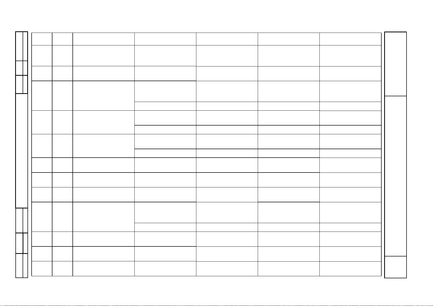
all Vario tractors
Tractor / General system
Vario Tractors - Fault Codes
B
Faults
12/1999
0000 000001
B
f
34/58
Capitel Docu-No.Index
Date Version
Page
Vario Tractors - Fault Codes
6.1.03 S019 Left external 'Rear PTO
ON / OFF' pushbutton
Signal fault PTO can be engaged by
pressing emergency key
in cab for 5 seconds.
'PTO's' circuit diagram REAR PTO
ENHANCED CONTROL
6.1.04 Y008 Rear PTO clutch
solenoid valve
Actuation fault PTO disengages 'PTO's' circuit diagram REAR PTO
ENHANCED CONTROL
6.1.05 B021 Hall speed sensor at
rear PTO clutch
Signal fault PTO can be engaged by
pressing emergency key
in cab for 5 seconds.
'PTO's' circuit diagram REAR PTO
ENHANCED CONTROL
12 V supply fault A013 fuse 33
6.1.06 A004 Rear PTO speed
selector key 1
Key / A004 signal fault REAR PTO
ENHANCED CONTROL
Bus fault A004 / A002
6.1.07 A004 Rear PTO speed
selector key 2
Signal fault REAR PTO
ENHANCED CONTROL
Bus fault A004 / A002
6.1.08 Y026 Rear PTO speed 1
solenoid valve
Actuation fault REAR PTO
ENHANCED CONTROL
6.1.09 Y027 Rear PTO speed 2
solenoid valve
Actuation fault REAR PTO
ENHANCED CONTROL
6.1.0A A004 'Active' key (only NA
version)
Key / A004 signal fault PTO cannot be engaged REAR PTO
ENHANCED CONTROL
6.1.10 B020 Hall speed sensor on
rear PTO stub shaft
Signal fault PTO can be engaged by
pressing emergency key
in cab for 5 seconds.
REAR PTO
ENHANCED CONTROL
12 V supply fault A013 fuse 32
6.1.11 A004 Rear PTO automatic
mode key
Signal fault PTO disengages,
automatic mode OFF
'PTO's' circuit diagram REAR PTO
ENHANCED CONTROL
6.1.15 A004 NEUTRAL speed
selector key
Key / A004 signal fault PTO speed cannot be
modified or selected
'PTO's' circuit diagram REAR PTO
ENHANCED CONTROL
6.1.16 A004 540 rpm speed selector
key
Key / A004 signal fault PTO speed cannot be
modified or selected
'PTO's' circuit diagram REAR PTO
ENHANCED CONTROL
Fault
code
Id code Brief description Description Consequences Link FENDIAS / Note
Page 39

all Vario tractors
Tractor / General system
Vario Tractors - Fault Codes
B
Faults
12/1999
0000 000001
B
f
35/58
Capitel Docu-No.
Index
Date Version
Page
Vario Tractors - Fault Codes
6.1.17 A004 750 rpm speed selector
key
Key / A004 signal fault PTO speed cannot be
modified or selected
'PTO's' circuit diagram REAR PTO
ENHANCED CONTROL
6.1.18 A004 1000 rpm speed selector
key
Key / A004 signal fault PTO speed cannot be
modified or selected
'PTO's' circuit diagram REAR PTO
ENHANCED CONTROL
6.1.1A Y026 Rear PTO speed 540
solenoid valve
Actuation fault PTO cannot be engaged 'PTO's' circuit diagram REAR PTO
ENHANCED CONTROL
6.1.1B Y027
Not
900
Rear PTO speed 750
solenoid valve
Actuation fault PTO cannot be engaged 'PTO's' circuit diagram REAR PTO
ENHANCED CONTROL
6.1.1B Y026
Only
900
Rear PTO speed 750
solenoid valve
Actuation fault PTO cannot be engaged 'PTO's' circuit diagram REAR PTO
ENHANCED CONTROL
6.1.1C Y028
Not
900
Rear PTO speed 1000
solenoid valve
Actuation fault PTO cannot be engaged 'PTO's' circuit diagram REAR PTO
ENHANCED CONTROL
6.1.1C Y027
Only
900
Rear PTO speed 1000
solenoid valve
Actuation fault PTO cannot be engaged 'PTOs' circuit diagram REAR PTO
ENHANCED CONTROL
6.1.41 A004 Rear PTO ON / OFF key
(in cab)
has been pressed for
more than 30 seconds,
mechanical or electrical
fault in key.
Speed selection moves
to neutral, no
preselection possible
'PTOs' circuit diagram REAR PTO
ENHANCED CONTROL
6.1.42 S020 Right external 'Rear
PTO ON / OFF'
pushbutton
has been pressed for
more than 30 seconds,
mechanical or electrical
fault in key.
No speed selection,
PTO cannot be engaged
'PTOs' circuit diagram REAR PTO
ENHANCED CONTROL
6.1.43 S019 Left external 'Rear PTO
ON / OFF' pushbutton
has been pressed for
more than 30 seconds,
mechanical or electrical
fault in key.
No speed selection,
PTO cannot be engaged
'PTOs' circuit diagram REAR PTO
ENHANCED CONTROL
Fault
code
Id code Brief description Description Consequences Link FENDIAS / Note
Page 40

all Vario tractors
Tractor / General system
Vario Tractors - Fault Codes
B
Faults
12/1999
0000 000001
B
f
36/58
Capitel Docu-No.Index
Date Version
Page
Vario Tractors - Fault Codes
6.1.45 B021 Hall speed sensor at
rear PTO clutch
Speed selection in
neutral, clutch not
engaged, B021 shows
speed, clutch disc
package does not
separate, PTO brake
non operational
Activating speeds
remains possible, press
'Engage PTO' key for
more than 5 seconds
(emergency mode).
'PTOs' circuit diagram REAR PTO
ENHANCED CONTROL
Speed is selected,
clutch 100% engaged,
clutch speed deviates by
more than 20% from
engine speed. Clutch is
slipping.
Activating speeds
remains possible, press
'Engage PTO' key for
more than 5 seconds
(emergency mode).
'PTOs' circuit diagram REAR PTO
ENHANCED CONTROL
Speed of PTO clutch is
slower than PTO stub
speed
Activating speeds
remains possible, press
'Engage PTO' key for
more than 5 seconds
(emergency mode).
'PTOs' circuit diagram REAR PTO
ENHANCED CONTROL
6.1.4A A004 'Active' key (only NA
version)
has been pressed for
more than 30 seconds,
mechanical or electrical
fault in key.
No PTO operation
possible
REAR PTO
ENHANCED CONTROL
Fault
code
Id code Brief description Description Consequences Link FENDIAS / Note
Page 41

all Vario tractors
Tractor / General system
Vario Tractors - Fault Codes
B
Faults
12/1999
0000 000001
B
f
37/58
Capitel Docu-No.
Index
Date Version
Page
Vario Tractors - Fault Codes
6.1.50 B020 Rear PTO stub shaft
Hall speed sensor
Speed at PTO stub shaft
> 1300 rpm, signal fault
in Hall sensor ( B020 or
B021)
Activating speeds
remains possible, press
'Engage PTO' key for
more than 5 seconds
(emergency mode).
'PTOs' circuit diagram REAR PTO
ENHANCED CONTROL
Selected speed is
active, speed at stub is
lower than clutch speed,
power supply fault to
Hall sensor B020, speed
selection solenoid valve
(Y026, Y027, Y028)
stuck in 'OFF' position.
Electric speed selection
remains possible, press
'Engage PTO' key for
more than 5 seconds
(emergency mode). In
case of a faulty solenoid
valve, corresponding
speed cannot be
engaged.
'PTOs' circuit diagram REAR PTO
ENHANCED CONTROL
6.1.55 A004 NEUTRAL speed
selector key
has been pressed for
more than 30 seconds,
mechanical or electrical
fault in key.
All speeds can be
selected and engaged.
Neutral cannot be
selected.
'PTOs' circuit diagram REAR PTO
ENHANCED CONTROL
6.1.56 A004 540 rpm speed selector
key
has been pressed for
more than 30 seconds,
mechanical or electrical
fault in key.
As long as '540' is
selected, engagement
can occur. '1000' and
'750' can be selected,
press 'Engage PTO' key
for longer than 5
seconds. '540' cannot be
selected.
'PTOs' circuit diagram REAR PTO
ENHANCED CONTROL
6.1.57 A004 750 rpm speed selector
key
has been pressed for
more than 30 seconds,
mechanical or electrical
fault in key.
As long as '750' is
selected, engagement
can occur. '1000' and
'540' can be selected,
press 'Engage PTO' key
for longer than 5
seconds. '750' cannot be
selected.
'PTOs' circuit diagram REAR PTO
ENHANCED CONTROL
Fault
code
Id code Brief description Description Consequences Link FENDIAS / Note
Page 42

all Vario tractors
Tractor / General system
Vario Tractors - Fault Codes
B
Faults
12/1999
0000 000001
B
f
38/58
Capitel Docu-No.Index
Date Version
Page
Vario Tractors - Fault Codes
6.1.58 A004 1000 rpm speed selector
key
has been pressed for
more than 30 seconds,
mechanical or electrical
fault in key.
As long as '1000' is
selected, engagement
can occur. '750' and
'540' can be selected,
press 'Engage PTO' key
for longer than 5
seconds. '1000' cannot
be selected.
'PTOs' circuit diagram REAR PTO
ENHANCED CONTROL
6.1.60 B020
B021
PTO stub shaft Hall
speed sensor B020, Hall
speed sensor on PTO
clutch B021
Actual speed of stub
shaft differs by more
than plus / minus 12%
from setpoint speed of
PTO clutch. Solenoid
valve (Y026, Y027,
Y028) wrongly wired or
seized. Mechanical fault
in speed selector . Signal
fault at Hall sensor
(B020, B021)
Electric speed selection
remains possible, press
'Engage PTO' key for
more than 5 seconds
(emergency mode). In
case of a faulty solenoid
valve, corresponding
speed cannot be
engaged.
'PTOs' circuit diagram REAR PTO
ENHANCED CONTROL
6.1.A1 A004 Rear PTO 'ON' key Communication fault 'PTOs' circuit diagram REAR PTO
ENHANCED CONTROL
6.1.AA A004 'Active' key (only NA
version)
Communication fault REAR PTO
ENHANCED CONTROL
6.1.B0 A004 CAN-bus
communication
restricted
Rear PTO
non-operational
EOL reprogramming
necessary.
6.1.B5 A004 NEUTRAL speed
selector key
Communication fault REAR PTO
ENHANCED CONTROL
6.1.B6 A004 540 rpm speed selector
key
Communication fault REAR PTO
ENHANCED CONTROL
6.1.B7 A004 750 rpm speed selector
key
Communication fault REAR PTO
ENHANCED CONTROL
6.1.B8 A004 1000 rpm speed selector
key
Communication fault REAR PTO
ENHANCED CONTROL
Fault
code
Id code Brief description Description Consequences Link FENDIAS / Note
Page 43

all Vario tractors
Tractor / General system
Vario Tractors - Fault Codes
B
Faults
12/1999
0000 000001
B
f
39/58
Capitel Docu-No.
Index
Date Version
Page
Vario Tractors - Fault Codes
6.1.E0 A002 ECU, enhanced control Checksum error
parameter current
control for speed
selector
Run new EOL
programming.
6.1.E1 A002 ECU, enhanced control Checksum error PTO
parametrisation
Run new EOL
programming.
7.1.01 A004 Front PTO ON / OFF key Key / A004 signal fault 'PTOs' circuit diagram FRONT PTO
ENHANCED CONTROL
Bus fault A004 / A002
7.1.02 S041 'Release front PTO
brake' external
pushbutton
Signal fault 'PTOs' circuit diagram FRONT PTO
ENHANCED CONTROL
7.1.03 Y034 'Release brake' front
PTO solenoid valve
Actuation fault 'PTOs' circuit diagram
7.1.04 Y011 'PTO clutch' front PTO
solenoid valve
Actuation fault FRONT PTO
ENHANCED CONTROL
7.1.05 B002 Front PTO Hall speed
sensor
Signal fault 'PTOs' circuit diagram FRONT PTO
ENHANCED CONTROL
12 V supply fault A013 fuse 22
7.1.06 S042 Front PTO speed
sensor 1 solenoid switch
Signal fault Service Training ML 200
(X 990.005.023.027en)
FRONT PTO
ENHANCED CONTROL
7.1.07 S042 Front PTO speed
sensor 2 solenoid switch
Signal fault Service Training ML 200
(X 990.005.023.027en)
FRONT PTO
ENHANCED CONTROL
7.1.08 S042 Front PTO speed
sensor 3 solenoid switch
Signal fault Service Training ML 200
(X 990.005.023.027en)
FRONT PTO
ENHANCED CONTROL
7.1.09 A004 Front PTO automatic
mode key
Key / A004 signal fault 'PTOs' circuit diagram FRONT PTO
ENHANCED CONTROL
Bus fault A004 / A002
7.1.0A A004 'Active' key
(only NA version)
Key / A004 signal fault FRONT PTO
ENHANCED CONTROL
Bus fault A004 / A002
Fault
code
Id code Brief description Description Consequences Link FENDIAS / Note
Page 44

all Vario tractors
Tractor / General system
Vario Tractors - Fault Codes
B
Faults
12/1999
0000 000001
B
f
40/58
Capitel Docu-No.Index
Date Version
Page
Vario Tractors - Fault Codes
7.1.41 A004 Front PTO 'ON' key Plausibility error, key
has been pressed for
more than 30 seconds
FRONT PTO
ENHANCED CONTROL
7.1.42 S041 'Release brake' key Plausibility error, key
has been pressed for
more than 30 seconds
FRONT PTO
ENHANCED CONTROL
7.1.4A A004 'Active' key (only NA
version)
Plausibility error, key
has been pressed for
more than 30 seconds
FRONT PTO
ENHANCED CONTROL
7.1.A1 A004 Front PTO 'ON' key Communication fault FRONT PTO
ENHANCED CONTROL
7.1.A2 Communication fault FRONT PTO
ENHANCED CONTROL
7.1.AA A004 'Active' key (only NA
version)
Communication fault FRONT PTO
ENHANCED CONTROL
8.1.43 A004 Automatic function
(switching from control
console to joystick)
Fault in switch/A004
contact
Switching not possible 'Electrohydraulic power
lift control' circuit
diagram
REAR EPC
ACKNOWLEDGEMENTS / STATUS
CAN (K-bus) fault
A004 / A005
8.3.11 A005,
A014,
Y 021
Rear EPC, 'Raise'
function
Fault in signal line to
valve
Control locked 'Electrohydraulic power
lift control' circuit
diagram
REAR EPC
ACTUATORS / STATUS
Solenoid valve faulty
E-box fault
8.3.12 Y021 Rear EPC, 'Lower'
function
Fault in signal line to
valve
Control locked 'Electrohydraulic power
lift control' circuit
diagram
REAR EPC
ACTUATORS / STATUS
Solenoid valve faulty
E-box fault
Fault
code
Id code Brief description Description Consequences Link FENDIAS / Note
Page 45

all Vario tractors
Tractor / General system
Vario Tractors - Fault Codes
B
Faults
12/1999
0000 000001
B
f
41/58
Capitel Docu-No.
Index
Date Version
Page
Vario Tractors - Fault Codes
8.3.14 S029 'Raise' rear power lift
external pushbutton,
cab, left rear
Signal line fault, key fault Control locked 'Electrohydraulic power
lift control' circuit
diagram
REAR EPC EXTERNAL
PUSHBUTTONS
8.3.15 S030 'Lower' rear power lift
external pushbutton,
cab, left rear
Signal line fault Control locked 'Electrohydraulic power
lift control' circuit
diagram
REAR EPC EXTERNAL
PUSHBUTTONS
8.3.16 A005,
A014
E-box rear power lift,
ECU, OBE
Stable voltage < 1 volt Control locked 'Electrohydraulic power
lift control' circuit
diagram
REAR EPC CURRENT
FAULT STATUS
8.3.17 A005,
A014
E-box rear power lift,
ECU, OBE
Supply voltage >18 volt Control locked 'Electrohydraulic power
lift control' circuit
diagram
8.3.18 S027 'Raise' rear power lift
external pushbutton,
cab, right rear
Signal line fault Control locked 'Electrohydraulic power
lift control' circuit
diagram
REAR EPC EXTERNAL
PUSHBUTTONS
Key fault
8.3.19 S028 'Lower' rear power lift
external pushbutton,
cab, right rear
Signal line fault Control locked 'Electrohydraulic power
lift control' circuit
diagram
REAR EPC EXTERNAL
PUSHBUTTONS
Key fault
8.3.21 Rotary control for
'Position/traction hybrid
control' for rear EPC
Signal fault Service Training EPC C
(X 990.005.023.026en)
8.3.22 B030 Rear EPC position
sensor
Signal fault Control locked 'Electrohydraulic power
lift control' circuit
diagram
REAR EPC SETPOINT /
POSITION SENSOR
Fault in 9.5 V supply to
A005
8.3.23 A004 Rear EPC 'Depth
control' setpoint setting
Signal line fault Control locked REAR EPC SETPOINT /
POSITION SENSOR
8.3.24 Rear power lift 'lift height
limit' rotary control
Signal fault Control locked Service Training EPC C
(X 990.005.023.026en)
Fault
code
Id code Brief description Description Consequences Link FENDIAS / Note
Page 46

all Vario tractors
Tractor / General system
Vario Tractors - Fault Codes
B
Faults
12/1999
0000 000001
B
f
42/58
Capitel Docu-No.Index
Date Version
Page
Vario Tractors - Fault Codes
8.3.26 External position sensor
for rear power lift
Signal line fault Control locked 'Electrohydraulic power
lift control' circuit
diagram
Sensor out of position
Sensor fault
8.3.28 A004 Control console ECU Fault in rear EPC quick
lift switch
'Raise'and 'Lower' only
possible via external
buttons.
'Electrohydraulic power
lift control' circuit
diagram
REAR EPC
ACKNOWLEDGEMENTS / STATUS
8.3.31 B031 Rear EPC right
draft-sensing pin
Signal line fault Restricted control quality
with traction control
'Electrohydraulic power
lift control' circuit
diagram
EPC REAR DRAUGHT
SENSING PIN
9.5 V supply fault
Sensor fault
8.3.32 B032 Rear EPC left draught
sensing pin
Signal line fault Restricted control quality
with traction control
'Electrohydraulic power
lift control' circuit
diagram
EPC-REAR DRAUGHT
SENSING PIN
Fault in 9.5 V supply to
A005
Sensor fault
8.3.34 Rear power lift 'Lowering
speed' rotary control
Signal fault Cannot be changed Service Training EPC C
(X 990.005.023.026en)
8.3.35 Rear power lift
'Operating mode' rotary
control
Signal fault Cannot be changed Service Training EPC C
(X 990.005.023.026en)
8.3.38 Rear power lift pressure
sensor
Signal fault, pressure
sensor fault
Control is continued Service Training EPC C
(X 990.005.023.026en)
8.3.39 Rear power lift 'Rapid
lowering / Hitch lift'
switch
Signal fault Control is continued Service Training EPC C
(X 990.005.023.026en)
Fault
code
Id code Brief description Description Consequences Link FENDIAS / Note
Page 47

all Vario tractors
Tractor / General system
Vario Tractors - Fault Codes
B
Faults
12/1999
0000 000001
B
f
43/58
Capitel Docu-No.
Index
Date Version
Page
Vario Tractors - Fault Codes
8.3.40 A004 Rear power lift quick lift
switch
Fault in switch /
A004 contact
Raising and lowering
only via external controls
'Electrohydraulic power
lift control' circuit
diagram
REAR EPC ACTUA TOR
/ STATUS
CAN (K-Bus) fault
A004 / A005
8.3.41 A004 Rear power lift rapid lift
control
Fault in switch/A004
contact
Rapid lowering system
not functioning
'Electrohydraulic power
lift control' circuit
diagram
REAR EPC ACTUA TOR
/ STATUS
CAN (K-Bus) fault
A004 / A005
8.3.42 A004 Rear EPC, hitch function Fault in switch/A004
contact
Hitch function not
operational
'Electrohydraulic power
lift control' circuit
diagram
REAR EPC ACTUA TOR
/ STATUS
CAN (K-bus) fault
A004 / A005
8.3.43 A004 Automatic function
(switching from control
console to joystick)
Fault in switch/
A004 contact
Switching not possible 'Electrohydraulic power
lift control' circuit
diagram
REAR EPC ACTUA TOR
/ STATUS
CAN fault A004 / A005
8.3.50 B031
draught
sensing pin
Rear EPC right draught
sensing pin
Draught sensing pin is
overloaded as a result of
twisting lift in upper
range (90-100% lift
height) due to too tight
setting
Fault code will not be
stored
'Electrohydraulic power
lift control' circuit
diagram
EPC-REAR DRAUGHT
SENSING PIN
8.3.51 B032
draught
sensing pin
Rear EPC left draught
sensing pin
Draught sensing pin is
overloaded as a result of
twisting lift in upper
range (90-100% lift
height) due to too tight
setting
Fault code will not be
stored
'Electrohydraulic power
lift control' circuit
diagram
EPC-REAR DRAUGHT
SENSING PIN
9.1.50 Y019 Spool valve fault Valve cannot be
identified via bus line.
No valve operation
available
Signal flow diagram
A002 CAN II pin 4 and 5
FRONT POWER LIFT /
VENDI
Fault
code
Id code Brief description Description Consequences Link FENDIAS / Note
Page 48

all Vario tractors
Tractor / General system
Vario Tractors - Fault Codes
B
Faults
12/1999
0000 000001
B
f
44/58
Capitel Docu-No.Index
Date Version
Page
Vario Tractors - Fault Codes
9.1.51 Y019 Spool valve fault EEPROM inconsistent Valve moves into neutral
position
FRONT POWER LIFT /
VENDI
9.1.52 Spool valve fault Supply voltage > 8 volts Valve moves into neutral
position
FRONT POWER LIFT /
VENDI
9.1.53 Y019 Spool valve fault Supply voltage
> 18 volts
V alve moves into neutral
position
FRONT POWER LIFT /
VENDI
9.1.54 Y019 Spool valve fault Main piston travel too
short due to drop of
control pressure below
22 bar
V alve moves into neutral
position
Test control pressure
M5, test diaphragm
accumulator,
test RV7/ FP
FRONT POWER LIFT /
VENDI
Hydraulic oil
temperature too low
9.1.55 Y019 Spool valve fault Overvoltage (> 45 volts) Valve moves into neutral
position
9.1.56 Y019 Spool valve fault Magnet output stage
fault within spool valve
V alve moves into neutral
position
FRONT POWER LIFT /
VENDI
9.1.57 Y019 Spool valve fault Internal position sensor
fault
V alve moves into neutral
position
FRONT POWER LIFT /
VENDI
9.1.58 Y019 Spool valve fault Main piston cannot
return to neutral position
because of oil
contamination.
Manual actuation must
not have play, slider
must go into the middle
position by itself
FRONT POWER LIFT /
VENDI
9.1.59 Y019 Spool valve fault Main piston cannot
return to neutral position
when switched on
because of oil
contamination.
FRONT POWER LIFT /
VENDI
9.1.5A Y019 Spool valve fault Main piston deflected
too far
V alve moves into neutral
position
FRONT POWER LIFT /
VENDI
9.1.5B Y019 Spool valve fault Floating position is not
reached
V alve moves into neutral
position
FRONT POWER LIFT /
VENDI
Fault
code
Id code Brief description Description Consequences Link FENDIAS / Note
Page 49

all Vario tractors
Tractor / General system
Vario Tractors - Fault Codes
B
Faults
12/1999
0000 000001
B
f
45/58
Capitel Docu-No.
Index
Date Version
Page
Vario Tractors - Fault Codes
9.1.5C Y019 Spool valve fault Floating position has
been set manually
No consequences FRONT POWER LIFT /
VENDI
9.1.5F Y019 Spool valve fault Setpoint message
missing
V alve moves into neutral
position
FRONT POWER LIFT /
VENDI
Configuration message
missing
Setpoint message is not
plausible
Configuration message
is not plausible
Potentiometer or PWM
fault
9.1.A0 A002 ECU, enhanced control EEPROM fault while
storing
Set values (enhanced
controls) are not stored.
9.1.A1 A002 ECU, enhanced control EEPROM fault while
loading
Set values (enhanced
controls) cannot be
read.
9.1.B0 B040 Position sensor Not calibrated No position control
available
FRONT POWER LIFT
calibration code "9002"
9.1.B1 B040 Position sensor Signal fault No position control
available
'Spool valves 2' circuit
diagram
Front power lift
8.5 V supply fault A013 fuse 11
9.1.B2 A004 Depth control setpoint
potentiometer
Not calibrated Setpoint cannot be set FRONT POWER LIFT
calibration code '9001'
9.1.B3 A004 Depth control setpoint
potentiometer
Switch / A004 signal
fault
Setpoint cannot be set Front power lift
9.1.C0 A004 Control console Not available or bus not
connected
9.1.C1 A004 Automatic (switching
from control console to
armrest)
Key fault Front power lift
Fault
code
Id code Brief description Description Consequences Link FENDIAS / Note
Page 50

all Vario tractors
Tractor / General system
Vario Tractors - Fault Codes
B
Faults
12/1999
0000 000001
B
f
46/58
Capitel Docu-No.Index
Date Version
Page
Vario Tractors - Fault Codes
9.1.C2 A004 Valve locked Key fault Front power lift
9.1.C3 A004 Floating position Key fault Front power lift
9.1.C4 A004 'Lift' quick lift switch Key fault Front power lift
9.1.C5 A004 'Lower' quick lift switch Key fault Front power lift
9.1.C6
9.1.C7
9.1.C8
9.1.C9
9.1.CA
A004 Control console CAN-bus fault Malfunctions which
cannot be further
specified
9.1.D0 S021 'Raise' front power lift
external pushbutton
Key fault Non-operational 'Spool valves 2' circuit
diagram
Front power lift
9.1.D1 S022 'Lower' front power lift
external pushbutton
Key fault Non-operational 'Spool valves 2' circuit
diagram
Front power lift
9.1.D2 S021,
S022
External button front
power lift 'raise', external
button front power lift
'lower'
Button double operation
(button possibly stuck)
'Spool valves 2' circuit
diagram
Front power lift
9.3.11 Rear EPC, 'Raise'
function
Fault in signal line to
valve
Control locked Service Training EPC C
(X 990.005.023.026en)
Solenoid valve faulty
E-box fault
9.3.12 Front EPC, 'Lower'
function
Fault in signal line to
valve
Control locked Service Training EPC C
(X 990.005.023.026en)
Solenoid valve faulty
E-box fault
9.3.14 Pushbutton ext. front
power lift "raise"
Signal line fault, key fault Control locked Service Training EPC C
(X 990.005.023.026en)
9.3.15 Pushbutton ext. front
power lift 'lower'
Signal line fault Control locked Service Training EPC C
(X 990.005.023.026en)
Fault
code
Id code Brief description Description Consequences Link FENDIAS / Note
Page 51

all Vario tractors
Tractor / General system
Vario Tractors - Fault Codes
B
Faults
12/1999
0000 000001
B
f
47/58
Capitel Docu-No.
Index
Date Version
Page
Vario Tractors - Fault Codes
9.3.17 Battery Supply voltage >18 volt Control locked Service Training EPC C
(X 990.005.023.026en)
9.3.21 Rotary control for
'position/traction hybrid
control' for front EPC
Signal fault Service Training EPC C
(X 990.005.023.026en)
9.3.22 Front EPC rotary
position sensor
Signal fault Control locked Service Training EPC C
(X 990.005.023.026en)
9.3.23 Front EPC 'Depth
control' setpoint setting
Signal line fault Control locked Service Training EPC C
(X 990.005.023.026en)
9.3.24 Front power lift 'lift
height limit' rotary
control
Signal fault Control locked Service Training EPC C
(X 990.005.023.026en)
9.3.26 External position sensor
for front power lift
Signal line fault Control locked Service Training EPC C
(X 990.005.023.026en)
9.3.28 Quick lift switch, front Fault in front EPC quick
lift switch
'Raise' and 'Lower' only
possible via external
buttons.
Service Training EPC C
(X 990.005.023.026en)
9.3.34 Front power lift
'Lowering speed' rotary
control
Signal fault Cannot be changed Service Training EPC C
(X 990.005.023.026en)
A.1.10 Y015 Spool valve fault, valve 1 Valve cannot be
recognised by valve bus
No valve operation
available
Signal flow diagram
A002 CAN II pin 4 and 5
A.1.1 1 Y015 Spool valve fault, valve 1 EEPROM inconsistent V alve moves into neutral
position
A.1.12 Y015 Spool valve fault, valve 1 Supply voltage < 8 volts V alve moves into neutral
position
A.1.13 Y015 Spool valve fault, valve 1 Supply voltage
> 18 volts
V alve moves into neutral
position
Fault
code
Id code Brief description Description Consequences Link FENDIAS / Note
Page 52

all Vario tractors
Tractor / General system
Vario Tractors - Fault Codes
B
Faults
12/1999
0000 000001
B
f
48/58
Capitel Docu-No.Index
Date Version
Page
Vario Tractors - Fault Codes
A.1.14 Y015 Spool valve fault, valve 1 Main piston travel too
short due to drop of
control pressure below
22 bar
V alve moves into neutral
position
Test control pressure
M5, test diaphragm
accumulator, test RV7/
FP
ELECTRICAL VALVES
VALVE 1 / VENDI
Hydraulic oil
temperature too low
A.1.15 Y015 Spool valve fault, valve 1 Overvoltage (> 45 volts) Valve moves into neutral
position
A.1.16 Y015 Spool valve fault, valve 1 Magnet output stage
fault within spool valve
V alve moves into neutral
position
ELECTRICAL VALVES
VALVE 1 / VENDI
A.1.17 Y015 Spool valve fault, valve 1 Internal position sensor
fault
V alve moves into neutral
position
ELECTRICAL VALVES
VALVE 1 / VENDI
A.1.18 Y015 Spool valve fault, valve 1 Main piston cannot
return to neutral position
because of oil
contamination.
Undefined and
uncontrolled functions
can occur, DANGER!
Manual actuation must
not have play, slider
must go into the middle
position by itself
ELECTRICAL VALVES
VALVE 1 / VENDI
A.1.19 Y015 Spool valve fault, valve 1 Main piston cannot
return to neutral position
when switched on
because of oil
contamination.
ELECTRICAL VALVES
VALVE 1 / VENDI
A.1.1A Y015 Spool valve fault, valve 1 Main piston deflected
too far
V alve moves into neutral
position
ELECTRICAL VALVES
VALVE 1 / VENDI
A.1.1B Y015 Spool valve fault, valve 1 Floating position is not
reached
V alve moves into neutral
position
ELECTRICAL VALVES
VALVE 1 / VENDI
A.1.1C Y015 Spool valve fault, valve 1 Floating position has
been set manually
No consequences ELECTRICAL VALVES
VALVE 1 / VENDI
Fault
code
Id code Brief description Description Consequences Link FENDIAS / Note
Page 53

all Vario tractors
Tractor / General system
Vario Tractors - Fault Codes
B
Faults
12/1999
0000 000001
B
f
49/58
Capitel Docu-No.
Index
Date Version
Page
Vario Tractors - Fault Codes
A.1.1F Y015 Spool valve fault, valve 1 Setpoint message is
missing or not plausible
V alve moves into neutral
position
ELECTRICAL VALVES
VALVE 1 / VENDI
Configuration message
is missing or not
plausible
Potentiometer or PWM
fault
A.1.20 Y016 Spool valve fault, valve 2 Valve cannot be
recognised by valve bus
No valve operation
available
Signal flow diagram
A002 CAN II pin 4 and 5
A.1.21 Y016 Spool valve fault, valve 2 EEPROM inconsistent V alve moves into neutral
position
A.1.22 Y016 Spool valve fault, valve 2 Supply voltage < 8 volts V alve moves into neutral
position
A.1.23 Y016 Spool valve fault, valve 2 Supply voltage
> 18 volts
V alve moves into neutral
position
A.1.24 Y016 Spool valve fault, valve 2 Main piston travel too
short due to drop of
control pressure below
22 bar
V alve moves into neutral
position
Test control pressure
M5, test diaphragm
accumulator,
test RV7/ FP
ELECTRICAL VALVES
VALVE 2 / VENDI
Hydraulic oil
temperature too low
A.1.25 Y016 Spool valve fault, valve 2 Overvoltage (> 45 volts) Valve moves into neutral
position
A.1.26 Y016 Spool valve fault, valve 2 Magnet output stage
fault within spool valve
V alve moves into neutral
position
ELECTRICAL VALVES
VALVE 2 / VENDI
A.1.27 Y016 Spool valve fault, valve 2 Internal position sensor
fault
V alve moves into neutral
position
ELECTRICAL VALVES
VALVE 2 / VENDI
A.1.28 Y016 Spool valve fault, valve 2 Main piston cannot
return to neutral position
because of oil
contamination.
Undefined and
uncontrolled functions
can occur, DANGER!
Manual actuation must
not have play, slider
must go into the middle
position by itself
ELECTRICAL VALVES
VALVE 2 / VENDI
Fault
code
Id code Brief description Description Consequences Link FENDIAS / Note
Page 54

all Vario tractors
Tractor / General system
Vario Tractors - Fault Codes
B
Faults
12/1999
0000 000001
B
f
50/58
Capitel Docu-No.Index
Date Version
Page
Vario Tractors - Fault Codes
A.1.29 Y016 Spool valve fault, valve 2 Main piston cannot
return to neutral position
when switched on
because of oil
contamination.
ELECTRICAL VALVES
VALVE 2 / VENDI
A.1.2A Y016 Spool valve fault, valve 2 Main piston deflected
too far
V alve moves into neutral
position
ELECTRICAL VALVES
VALVE 2 / VENDI
A.1.2B Y016 Spool valve fault, valve 2 Floating position is not
reached
V alve moves into neutral
position
ELECTRICAL VALVES
VALVE 2 / VENDI
A.1.2C Y016 Spool valve fault, valve 2 Floating position has
been set manually
No consequences ELECTRICAL VALVES
VALVE 2 / VENDI
A.1.2F Y016 Spool valve fault, valve 2 Setpoint message is
missing or not plausible
V alve moves into neutral
position
ELECTRICAL VALVES
VALVE 2 / VENDI
Configuration message
is missing or not
plausible
Potentiometer or PWM
fault
A.1.30 Y017 Spool valve fault, valve 3 Valve cannot be
recognised by valve bus
No valve operation
available
Signal flow diagram
A002 CAN II pin 4 and 5
A.1.31 Y017 Spool valve fault, valve 3 EEPROM inconsistent V alve moves into neutral
position
A.1.32 Y017 Spool valve fault, valve 3 Supply voltage < 8 volts V alve moves into neutral
position
A.1.33 Y017 Spool valve fault, valve 3 Supply voltage
> 18 volts
V alve moves into neutral
position
A.1.34 Y017 Spool valve fault, valve 3 Main piston travel too
short due to drop of
control pressure below
22 bar
V alve moves into neutral
position
Test control pressure
M5, test diaphragm
accumulator, test RV7/
FP
ELECTRICAL VALVES
VALVE 3 / VENDI
Hydraulic oil
temperature too low
Fault
code
Id code Brief description Description Consequences Link FENDIAS / Note
Page 55

all Vario tractors
Tractor / General system
Vario Tractors - Fault Codes
B
Faults
12/1999
0000 000001
B
f
51/58
Capitel Docu-No.
Index
Date Version
Page
Vario Tractors - Fault Codes
A.1.35 Y017 Spool valve fault, valve 3 Overvoltage (> 45 volts) Valve moves into neutral
position
A.1.36 Y017 Spool valve fault, valve 3 Magnet output stage
fault within spool valve
V alve moves into neutral
position
ELECTRICAL VALVES
VALVE 3 / VENDI
A.1.37 Y017 Spool valve fault, valve 3 Internal position sensor
fault
V alve moves into neutral
position
ELECTRICAL VALVES
VALVE 3 / VENDI
A.1.38 Y017 Spool valve fault, valve 3 Main piston cannot
return to neutral position
because of oil
contamination.
Undefined and
uncontrolled functions
can occur, DANGER!
Manual actuation must
not have play, slider
must go into the middle
position by itself
ELECTRICAL VALVES
VALVE 3 / VENDI
A.1.39 Y017 Spool valve fault, valve 3 Main piston cannot
return to neutral position
when switched on
because of oil
contamination.
ELECTRICAL VALVES
VALVE 3 / VENDI
A.1.3A Y017 Spool valve fault, valve 3 Main piston deflected
too far
V alve moves into neutral
position
ELECTRICAL VALVES
VALVE 3 / VENDI
A.1.3B Y017 Spool valve fault, valve 3 Floating position is not
reached
V alve moves into neutral
position
ELECTRICAL VALVES
VALVE 3 / VENDI
A.1.3C Y017 Spool valve fault, valve 3 Floating position has
been set manually
No consequences ELECTRICAL VALVES
VALVE 3 / VENDI
A.1.3F Y017 Spool valve fault, valve 3 Setpoint message is
missing or not plausible
V alve moves into neutral
position
ELECTRICAL VALVES
VALVE 3 / VENDI
Configuration message
is missing or not
plausible
Potentiometer or PWM
fault
A.1.40 Y018 Spool valve fault, valve 4 Valve cannot be
recognised by valve bus
No valve operation
available
Signal flow diagram
A002 CAN II pin 4 and 5
A.1.41 Y018 Spool valve fault, valve 4 EEPROM inconsistent V alve moves into neutral
position
Fault
code
Id code Brief description Description Consequences Link FENDIAS / Note
Page 56

all Vario tractors
Tractor / General system
Vario Tractors - Fault Codes
B
Faults
12/1999
0000 000001
B
f
52/58
Capitel Docu-No.Index
Date Version
Page
Vario Tractors - Fault Codes
A.1.42 Y018 Spool valve fault, valve 4 Supply voltage < 8 volts V alve moves into neutral
position
A.1.43 Y018 Spool valve fault, valve 4 Supply voltage
> 18 volts
V alve moves into neutral
position
A.1.44 Y018 Spool valve fault, valve 4 Main piston travel too
short due to drop of
control pressure below
22 bar
V alve moves into neutral
position
Test control pressure
M5, test diaphragm
accumulator,
test RV7/ FP
ELECTRICAL VALVES
VALVE 4 / VENDI
Hydraulic oil
temperature too low
A.1.45 Y018 Spool valve fault, valve 4 Overvoltage (> 45 volts) Valve moves into neutral
position
A.1.46 Y018 Spool valve fault, valve 4 Magnet output stage
fault within spool valve
V alve moves into neutral
position
ELECTRICAL VALVES
VALVE 4 / VENDI
A.1.47 Y018 Spool valve fault, valve 4 Internal position sensor
fault
V alve moves into neutral
position
ELECTRICAL VALVES
VALVE 4 / VENDI
A.1.48 Y018 Spool valve fault, valve 4 Main piston cannot
return to neutral position
because of oil
contamination.
Undefined and
uncontrolled functions
can occur, DANGER!
Manual actuation must
not have play, slider
must go into the middle
position by itself
ELECTRICAL VALVES
VALVE 4 / VENDI
A.1.49 Y018 Spool valve fault, valve 4 Main piston cannot
return to neutral position
when switched on
because of oil
contamination.
ELECTRICAL VALVES
VALVE 4 / VENDI
A.1.4A Y018 Spool valve fault, valve 4 Main piston deflected
too far
V alve moves into neutral
position
ELECTRICAL VALVES
VALVE 4 / VENDI
A.1.4B Y018 Spool valve fault, valve 4 Floating position is not
reached
V alve moves into neutral
position
ELECTRICAL VALVES
VALVE 4 / VENDI
A.1.4C Y018 Spool valve fault, valve 4 Floating position has
been set manually
No consequences ELECTRICAL VALVES
VALVE 4 / VENDI
Fault
code
Id code Brief description Description Consequences Link FENDIAS / Note
Page 57

all Vario tractors
Tractor / General system
Vario Tractors - Fault Codes
B
Faults
12/1999
0000 000001
B
f
53/58
Capitel Docu-No.
Index
Date Version
Page
Vario Tractors - Fault Codes
A.1.4F Y018 Spool valve fault, valve 4 Setpoint message is
missing or not plausible
V alve moves into neutral
position
ELECTRICAL VALVES
VALVE 4 / VENDI
Configuration message
is missing or not
plausible
Potentiometer or PWM
fault
A.1.A0 A002 E-box EEPROM fault while
storing
A.1.A1 A002 E-box EEPROM fault while
loading
A.1.A2 More valves connected
than registered via
end-of-line
programming. Program.
Not all valves can be
operated
A.1.B0 A003,
A034
Crossgate lever Not calibrated Valves cannot be
operated
Calibration code '1001'
A.1.B1 A003,
A034
Crossgate lever X-axis signal fault Valves cannot be
operated
'Spool valves 1' circuit
diagram
SPOOL VALVES
OPERATION
A.1.B2 A003,
A034
Crossgate lever Y-axis signal fault Valves cannot be
operated
'Spool valves 1' circuit
diagram
SPOOL VALVES
OPERATION
A.1.B3 A003,
A034
Crossgate lever X and Y axis signal fault;
crossgate lever missing
Valves cannot be
operated
'Spool valves 1' circuit
diagram
SPOOL VALVES
OPERATION
A.1.B4 A003,
A034
Crossgate lever Zero position signals of
X- and Y-axes are not
identical to the 'Rest
position' signal
(=plausibility check)
Valves cannot be
operated
'Spool valves 1' circuit
diagram
SPOOL VALVES
OPERATION
A.1.B5 A003,
A034
Crossgate lever 'Rest position' signal
fault
Valves cannot be
operated
'Spool valves 1' circuit
diagram
SPOOL VALVES
OPERATION
A.1.C0 A004 Control console Not available or bus not
connected
Fault
code
Id code Brief description Description Consequences Link FENDIAS / Note
Page 58

all Vario tractors
Tractor / General system
Vario Tractors - Fault Codes
B
Faults
12/1999
0000 000001
B
f
54/58
Capitel Docu-No.Index
Date Version
Page
Vario Tractors - Fault Codes
A.1.C1 A004 Automatic (switching
from control console to
armrest)
Key fault SPOOL VALVES
OPERATION
A.1.C2 A004 Valve locked Key fault SPOOL VALVES
OPERATION
A.1.C3 A004 Control console Floating position key
faulty
No floating position SPOOL VALVES
OPERATION
A.1.C4 A004 Control console Time function key faulty No time function SPOOL VALVES
OPERATION
A.1.C5 A004 Switching function Key fault SPOOL VALVES
OPERATION
A.1.C6
A.1.C7
A.1.C8
A.1.C9
A.1.CA
A004 Control console CAN-bus fault Malfunctions which
cannot be further
specified
A.1.CB A034 Joystick CAN joystick not
available. (CAN bus
fault)
Valves cannot be
operated.
Run new EOL
programming.
A.1.CC A002,
A034
ECU, enhanced control,
joystick
CAN communication
fault ECU and joystick.
Limited valve operation Run new EOL
programming.
A.1.D1 A003,
A034
Joystick button for spool
valve 3 Raising /
Lowering
Key fault No valve operation
available
SPOOL VALVES
OPERATION
A.1.D3 A003,
A034
Joystick button for spool
valve 4 Raising /
Lowering
Key fault No valve operation
available
SPOOL VALVES
OPERATION
A.1.D4 S023 Release for external
operation / position of
front power lift
Solenoid switch or signal
fault
Impossible to switch
mode from hydraulic
connection to front
power lift
'Spool valves 1' circuit
diagram
STANDARD FRONT
POWER LIFT
Fault
code
Id code Brief description Description Consequences Link FENDIAS / Note
Page 59

all Vario tractors
Tractor / General system
Vario Tractors - Fault Codes
B
Faults
12/1999
0000 000001
B
f
55/58
Capitel Docu-No.
Index
Date Version
Page
Vario Tractors - Fault Codes
A.1.D5 S022 'Lower' external
pushbutton
No valve operation
available
'Spool valves 1' circuit
diagram
STANDARD FRONT
POWER LIFT or
ENHANCED-CONTROL FRONT POWER LIFT
A.1.D6 S021 External 'Raise'
pushbutton
No valve operation
available
'Spool valves 1' circuit
diagram
STANDARD FRONT
POWER LIFT or
ENHANCED-CONTROL FRONT POWER LIFT
A.1.D7 S036 Hydraulic oil level
sensor
Break in cable or sensor
disconnected
No further monitoring 'Spool valves 1' circuit
diagram
ENHANCED CONTROL
STEERING FLUID
LEVELS
A.1.D9 S036 Hydraulic oil level
sensor
Tank is empty All valves are locked 'Spool valves 1' circuit
diagram
ENHANCED CONTROL
STEERING FLUID
LEVELS
A.1.DA B022 'Kickout'
pressure-operated
switch (only in NA
model)
Switch fault 'Kickout' function not
available
'Spool valves 1' circuit
diagram
A.1.DB Hydraulic oil tank
characteristic
implausible.
Incorrect tank display EOL reprogramming
necessary.
A.1.DD S021,
S022
External button 'raise',
external button 'lower',
Button double operation
(button possibly stuck)
No valve operation
available
'Spool valves 2' circuit
diagram
STANDARD FRONT
POWER LIFT or
ENHANCED-CONTROL FRONT POWER LIFT
A.1.F0 Y032 Control pressure
solenoid valve
Fault in electric
actuation system or
solenoid valve.
Valves in neutral
position
'Spool valves 1' circuit
diagram
ELECTRICAL
VALVES 1-4
A.1.F1 Y033
MVV
'Flush valve' solenoid 12V supply fault No oil heating during
start-up process for LS
pump at low ambient
temperature
'Suspension' circuit
diagram
ELECTRICAL
VALVES 1-4
Fault
code
Id code Brief description Description Consequences Link FENDIAS / Note
Page 60

all Vario tractors
Tractor / General system
Vario Tractors - Fault Codes
B
Faults
12/1999
0000 000001
B
f
56/58
Capitel Docu-No.Index
Date Version
Page
Vario Tractors - Fault Codes
A.1.F2 Y032 Control pressure
solenoid valve
current too high
(short to ground)
Valves in neutral
position
'Spool valves 1' circuit
diagram
ELECTRICAL
VALVES 1-4
A.1.F3 Y032 Control pressure
solenoid valve
break in wiring Valves in neutral
position
'Spool valves 1' circuit
diagram
ELECTRICAL
VALVES 1-4
A.1.FA S067 External valve actuation
button 'raise'
Button faulty; signal line
faulty
External valve actuation
no longer possible
'Spool valves 1' circuit
diagram
A.1.FB S068 External valve actuation
button 'lower'
Button faulty; signal line
faulty
External valve actuation
no longer possible
'Spool valves 1' circuit
diagram
A.1.FC S067;
S068
External valve actuation
button 'raise' / 'lower'
Button double operation
(button possibly stuck)
External valve actuation
no longer possible
'Spool valves 1' circuit
diagram
B.1.11 A002 ECU, enhanced control Electrical fault in TI
automatic operation
(user teach-in fault
(ECU or sensor))
Teach-in does not
function
See also Chapter 9700
Reg. A - Principle of
Variotronic TI operation
('Teach-in')
ENHANCED CONTROL
TeachIn
B.1.12 A002,
A008
ECU enhanced control,
terminal
Electrical fault in TI
automatic operation
(user teach-in fault
(ECU or sensor))
Teach-in does not
function
See also Chapter 9700
Reg. A - Principle of
Variotronic TI operation
('Teach-in')
ENHANCED CONTROL
TeachIn
B.1.13 A002 ECU, enhanced control Electrical fault in TI
automatic operation
Teach-in does not
function
See also Chapter 9700
Reg. A - Principle of
Variotronic TI operation
('Teach-in')
ENHANCED CONTROL
TeachIn
B.1.14 A002 ECU, enhanced control Electrical fault in TI
automatic operation
Teach-in does not
function
See also Chapter 9700
Reg. A - Principle of
Variotronic TI operation
('Teach-in')
ENHANCED CONTROL
TeachIn
B.1.21 A002 ECU, enhanced control CAN Bus -
Communication fault in
TI automatic operation
Teach-in does not
function
See also Chapter 9700
Reg. A - Principle of
Variotronic TI operation
('Teach-in')
ENHANCED CONTROL
TeachIn
Fault
code
Id code Brief description Description Consequences Link FENDIAS / Note
Page 61

all Vario tractors
Tractor / General system
Vario Tractors - Fault Codes
B
Faults
12/1999
0000 000001
B
f
57/58
Capitel Docu-No.
Index
Date Version
Page
Vario Tractors - Fault Codes
B.1.22 A002,
A008
ECU enhanced control,
terminal
CAN Bus Communication fault
between
A008 - Terminal and
Teach-in (program run)
Teach-in does not
function
See also Chapter 9700
Reg. A - Principle of
Variotronic TI operation
('Teach-in')
B.1.23 A002,
A004
ECU enhanced control,
control console
CAN Bus Communication fault
between A004 - Control
console and Teach-in
(program run)
Teach-in does not
function
See also Chapter 9700
Reg. A - Principle of
Variotronic TI operation
('Teach-in')
ENHANCED CONTROL
TeachIn
B.1.24 A002,
A034
ECU enhanced control,
drive switch
CAN Bus Communication fault
between A034 - Drive
switch and Teach-in
(program run)
Teach-in does not
function
See also Chapter 9700
Reg. A - Principle of
Variotronic TI operation
('Teach-in')
ENHANCED CONTROL
TeachIn
B.1.41 A002 ECU, enhanced control 'Internal communication
Teach-in' error counter
overflow
Teach-in does not
function
See also Chapter 9700
Reg. A - Principle of
Variotronic TI operation
('Teach-in')
ENHANCED CONTROL
TeachIn
B.1.42 A002,
A008
ECU enhanced control,
terminal
Error counter overflow
between
A008 - Terminal and
Teach-in (program run)
Teach-in does not
function
See also Chapter 9700
Reg. A - Principle of
Variotronic TI operation
('Teach-in')
ENHANCED CONTROL
TeachIn
B.1.43 A002,
A004
ECU enhanced control,
control console
Error counter overflow
between A004 - Control
console and Teach-in
(program run)
Teach-in does not
function
See also Chapter 9700
Reg. A - Principle of
Variotronic TI operation
('Teach-in')
ENHANCED CONTROL
TeachIn
B.1.44 A002,
A034
ECU enhanced control,
drive switch
Error counter overflow
between A304 - Drive
switch and Teach-in
(program run)
Teach-in does not
function
See also Chapter 9700
Reg. A - Principle of
Variotronic TI operation
('Teach-in')
ENHANCED CONTROL
TeachIn
Fault
code
Id code Brief description Description Consequences Link FENDIAS / Note
Page 62

all Vario tractors
Tractor / General system
Vario Tractors - Fault Codes
B
Faults
12/1999
0000 000001
B
f
58/58
Capitel Docu-No.Index
Date Version
Page
Vario Tractors - Fault Codes
B.1.B0 A002 ECU, enhanced control Read error during
Teach-in (program run)
Teach-in does not
function
See also Chapter 9700
Reg. A - Principle of
Variotronic TI operation
('Teach-in')
ENHANCED CONTROL
TeachIn
B.1.B4 A002 ECU, enhanced control Teach-in error - working
storage function
Teach-in does not
function --- Switch
ignition OFF then ON, if
error occurs again
--> load new band edge
programming in ECU
Enhanced Control; if
error occurs again
--> replace ECU
Enhanced Control
ENHANCED CONTROL
TeachIn
F.1.00 A034 Joystick Initialisation error in
reading EEPROM
Check A034 - drive
switch with FENDIAS
diagnostics program
Run new EOL
programming
(A034 - joystick)
F.1.B0 A034 Joystick Routing data GD false Run new EOL
programming
(A034 - joystick)
F.1.F0 A034 Joystick Diagnosis / filter data
checksum error
Run new EOL
programming
(A034 - joystick)
F.1.FF A034 Joystick Byte address checksum
error
Run new EOL
programming
(A034 - joystick)
Fault
code
Id code Brief description Description Consequences Link FENDIAS / Note
Page 63

FENDT 411
Vario COM III 400 .. / 1001-
FENDT 412
FENDT 413
FENDT 414
FENDT 415
FENDT 712
FENDT 714
FENDT 716
FENDT 718
FENDT 818
FENDT 820
Vario COM III 401 .. / 1001-
Vario COM III 402 .. / 1001-
Vario COM III 403 .. / 1001-
Vario COM III 404 .. / 1001-
Vario COM III 724 .. / 1001-
Vario COM III 725 .. / 1001-
Vario COM III 726 .. / 1001-
Vario COM III 727 .. / 1001-
FENDT 400 / 700 / 800 Vario COM III
Vario COM III 729 .. / 1001-
Vario COM III 731 .. / 1001-
Fault code table
Fault code table
Tableau de codes défauts
Tableau de codes défauts
Tabella codici disturbi
Tabella codici disturbi
Tabla códiga averías
Tabla códiga averías
Storingscodetabel
StörcodetabelleStörcodetabelle
Storingscodetabel
/ 404 .. 1001-
/ 727 .. 1001- / 729 .. 1001- / 731 .. 1001-
400 .. 1001- / 401 .. 1001- / 402 .. 1001- / 403 .. 1001-
724 .. 1001- / 725 .. 1001- / 726 .. 1001-
Page 64

Page 65

FENDT 400 Vario COM III, FENDT 700 Vario COM III, FENDT 800 Vario COM III Faults
B
OVERALL SYSTEM/TRACTOR
Fault code table COM III
Service Training
400 .. 1001- 724 .. 1001- 731 .. 1001-
401 .. 1001- 725 .. 1001-
402 .. 1001- 726 .. 1001-
403 .. 1001- 727 .. 1001-
404 .. 1001- 729 .. 1001-
0000 B T000434
Ver sio n 1
20/09/2007
3
0000 - OVER ALL SYSTEM /TRACTORB-FaultsError code table COM III
Fault
code
DIN brief description Cause Consequences Reference FENDIAS / Note
0.0.11 A002 - ECU, enhanced control Data transfer A002 restricted
to A051
Tractor can be driven
using the foot throttle
Wiring diagram
Sheet 22 / 6
EOL programming
0.0.12 A008 - Terminal Bus fault No functions availa-
ble, no display
Wiring diagram
Sheet 22 / 6
0.0.13 A004 - ECU, control panel Bus fault No functions availa-
ble, no display
Wiring diagram
Sheet 22 / 6
0.0.14 A009 - Actuator unit Bus fault No functions availa-
ble, no display
Wiring diagram
Sheet 22 / 6
0.0.15 A002 - ECU, enhanced control Bus fault; 4WD differential
lock switch
No functions available, no display
Wiring diagram
Sheet 22 / 6
0.0.16 A002 - ECU, enhanced control Rear PTO bus fault No functions availa-
ble, no display
Wiring diagram
Sheet 22 / 6
0.0.17 A002 - ECU, enhanced control Front PTO bus fault No functions availa-
ble, no display
Wiring diagram
Sheet 22 / 6
0.0.18 A014 - ECU, EPC OBE Bus fault No functions availa-
ble, no display
Wiring diagram
Sheet 22 / 6
0.0.1A A002 - ECU, enhanced control
Y015 - Auxiliary control valve
Y016 - Auxiliary control valve
Y017 - Auxiliary control valve
Y018 - Auxiliary control valve
Y019 - Auxiliary control valve
Bus fault No functions availa-
ble, no display
Wiring diagram
Sheet 22 / 6
Sheet 26
Page 66

FENDT 400 Vario COM III, FENDT 700 Vario COM III, FENDT 800 Vario COM III Faults
B
OVERALL SYSTEM/TRACTOR
Fault code table COM III
400 .. 1001- 724 .. 1001- 731 .. 1001-
401 .. 1001- 725 .. 1001-
402 .. 1001- 726 .. 1001-
403 .. 1001- 727 .. 1001-
404 .. 1001- 729 .. 1001-
0000 B T000434
Ver sio n 1
20/09/2007
4
0.0.1B A002 - ECU, enhanced control Teach-in bus fault – master
(Variotronic TI) ("teach-in data
transfer faulty")
Emergency mode Wiring diagram
Sheet 22 / 6
0.0.1E ECU, Neumaier Neumaier reversing system
bus fault
Neumaier system not
functioning
(Neumaier service manual)
0.0.1F A034 - Driving switch, CAN bus Driving switch bus fault (driving switch data transfer faulty)
Emergency operation, auxiliary control
valve not functioning
Wiring diagram
Sheet 22 / 6
JOYSTICK
CAN - JOYSTICK
0.0.20 A007 - Instrument panel CAN bus fault between A007
and tractor electronics
No functions available, no display
Wiring diagram
Sheet 22 / 6
0.1.50 A007 - Instrument panel VDO instrument panel EEP-
ROM not programmed
Malfunctions in instrument panel
EOL programming
0.1.54 B019 - Sensor, compressed air sup-
ply
Sensor faulty,
Signal line fault
No display Wiring diagram
Sheet 24
12 V supply fault A013 fuse 25
0.1.55 S036 - Switch, hydraulic oil level in-
dicator
Sensor faulty,
Signal line fault
No monitoring Wiring diagram
Sheet 26
ENHANCED CONTROL
FLUID LEVELS
0.1.56 B089 - Temperature sensor, Deutz Sensor faulty,
Signal line fault
No monitoring Wiring diagram
Sheet 36
SERDIA
0.1.57 B092 - Sensor, charge air pressure/
temperature
Sensor faulty,
Signal line fault
No monitoring Wiring diagram
Sheet 36
SERDIA
0.1.59 B034 - Immersed tube sensor (fuel) Sensor faulty,
Signal line fault
No display Wiring diagram
Sheet 24
1. 1. 01 B055 - Sensor, foot throttle Signal too high, signal too low,
no signal for longer than 2000
ms
Chapter 2000 Reg.B
(EDC fault)
Wiring diagram
Sheet 35
TRANSMISSION
LOAD LIMIT CONTROL
Fault
code
DIN brief description Cause Consequences Reference FENDIAS / Note
Page 67

FENDT 400 Vario COM III, FENDT 700 Vario COM III, FENDT 800 Vario COM III Faults
B
OVERALL SYSTEM/TRACTOR
Fault code table COM III
Service Training
400 .. 1001- 724 .. 1001- 731 .. 1001-
401 .. 1001- 725 .. 1001-
402 .. 1001- 726 .. 1001-
403 .. 1001- 727 .. 1001-
404 .. 1001- 729 .. 1001-
0000 B T000434
Ver sio n 1
20/09/2007
5
1. 1. 0 3 B055 - Sensor, foot throttle No match B055 combination
sensor (PIN 3 to PIN 6)
Restricted operating
mode, Chapter 2000
Reg.B (EDC fault)
Wiring diagram
Sheet 35
TRANSMISSION
LOAD LIMIT CONTROL
Calibration code "4005"
1. 1. 0 4 A002 - ECU, enhanced control Tractor Management System
(TMS) checksum error
TMS is switching off EOL programming
1. 1. 0 5 A051 - ECU, engine control unit
(EDC 7).
Not able to read off engine
configuration from EDC control unit
TMS is switching off Wiring diagram
Sheet 35
1. 1. 0 6 A002 - ECU, enhanced control EST memory could not be re-
served
TMS non-operable EOL programming
1. 1. 0 7 A002 - ECU, enhanced control Motor parameter checksum
incorrect
Driving possible in
emergency operating mode
EOL programming
1. 1. 7 E B035 - Sensor, hand throttle Signal too high, signal too low. Restricted operating
mode, Chapter 2000
Reg.B (EDC fault)
Wiring diagram
Sheet 33
TRANSMISSION
LOAD LIMIT CONTROL
Faulty 8.5 V supply Fuse 26
1. 1. 7 F A034 - Driving switch, CAN bus Hand throttle memory keys
defective (electrical fault). No
communication with EST.
Last RPM speed is retained. Engine RPM
speed can be
changed using hand
or foot throttle.
JOYSTICK
CAN - JOYSTICK
1. 1. 9 E A002 - ECU, enhanced control
A004 - ECU, control panel
CAN connection (enhanced
control BUS): A002 to A004
ECU faulty
Restricted operating
mode, Chapter 2000
Reg.B (EDC fault)
Wiring diagram
Sheet 22 / 23
JOYSTICK
CAN - JOYSTICK
1. 1. 9 F A034 - Driving switch, CAN bus A034 driving switch (memory
keys) defective;
CAN connection A002 ECU to
A034 faulty
Restricted operating
mode, Chapter 2000
Reg.B (EDC fault)
Wiring diagram
Sheet 22 / 23
JOYSTICK
CAN - JOYSTICK
Fault
code
DIN brief description Cause Consequences Reference FENDIAS / Note
Page 68

FENDT 400 Vario COM III, FENDT 700 Vario COM III, FENDT 800 Vario COM III Faults
B
OVERALL SYSTEM/TRACTOR
Fault code table COM III
400 .. 1001- 724 .. 1001- 731 .. 1001-
401 .. 1001- 725 .. 1001-
402 .. 1001- 726 .. 1001-
403 .. 1001- 727 .. 1001-
404 .. 1001- 729 .. 1001-
0000 B T000434
Ver sio n 1
20/09/2007
6
1. 1. A 0 A051 - ECU, engine control unit
(EDC 7).
Wrong engine control unit
(A051), wrong EOL programming
Torque limited following fault grading.
Chapter 2000 Reg.B
(EDC fault)
EOL programming
new data record
1. 1. A 1 A002 - ECU, enhanced control
A051 - ECU, engine control unit
(EDC 7).
CAN enhanced control module (A002) connection to engine control unit (A051) faulty
Chapter 2000 Reg.B
(EDC fault)
Wiring diagram
Sheet 28
SERDIA
1. 1. B 0 A050 - ECU, basic control unit
A051 - ECU, engine control unit
(EDC 7).
CAN bus communication and
function restricted
restricted engine
function
EOL programming
1. 1. E 0 A002 - ECU, enhanced control EEPROM checksum is incor-
rect
Restricted operating
mode, Chapter 2000
Reg.B (EDC fault)
Calibration code "4002"
If the following errors occur (1.2...), they must be deleted in the engine control unit following error correction with SERDIA!
1. 2 . 0 0 A051 - ECU, engine control unit
(EDC 7).
Original error, Deutz SERDIA (delete error)
1. 2 . 01 G001 - Battery 1 (12 VDC) Input, battery,
battery voltage outside
setpoint range
Start not possible SERDIA (delete error)
FC:0016, 0017
1.2.02 B092 - Sensor, charge air pressure/
temperature
Boost pressure sensor,
break in wiring or short circuit.
Charge pressure
outside setpoint range
Reduced power Wiring diagram
Sheet 36
SERDIA (delete error)
FC:0020, 0021
1.2.03 B092 - Sensor, charge air pressure/
temperature
Sensor
Charge air temperature, break
in wiring or short circuit.
Charge air temperature above
setpoint value
Reduced power Wiring diagram
Sheet 36
SERDIA (delete error)
FC:0095, 0096
Fault
code
DIN brief description Cause Consequences Reference FENDIAS / Note
Page 69

FENDT 400 Vario COM III, FENDT 700 Vario COM III, FENDT 800 Vario COM III Faults
B
OVERALL SYSTEM/TRACTOR
Fault code table COM III
Service Training
400 .. 1001- 724 .. 1001- 731 .. 1001-
401 .. 1001- 725 .. 1001-
402 .. 1001- 726 .. 1001-
403 .. 1001- 727 .. 1001-
404 .. 1001- 729 .. 1001-
0000 B T000434
Ver sio n 1
20/09/2007
7
1.2.04 B089 - Temperature sensor, Deutz Coolant temperature sensor:
break in wiring or short circuit.
Coolant temperature outside
setpoint area
Wiring diagram
Sheet 36
SERDIA (delete error)
FC:0037, 0038
1.2.06 B085 - Camshaft speed
B088 - Crankshaft speed
Camshaft sensor defective or
signal absent;
Crankshaft sensor defective
or signal absent; RPM signals
from camshaft/crankshaft out
of phase
Starting possible after
prolonged unsuccessful attempt, engine runs "rough"
Wiring diagram
Sheet 36
SERDIA (delete error)
FC:004B, 004C, 004D, 004E,
004F, 0050
1.2.07 B091 - Sensor, water in fuel Fuel filter/water sedimentor
sensor, brake in wiring or
short circuit
Water level above setpoint
range
Drain water from fuel
filter
Wiring diagram
Sheet 36
SERDIA (delete error)
FC:0057, 0059
1.2.08 B087 - Fuel low pressure Brake in wiring or short circuit
Fuel low pressure outside setpoint rage
Check fuel system,
possibly air in system
or fuel filter clogged
Wiring diagram
Sheet 36
SERDIA (delete error)
FC:005A, 005B, 005E
1.2.0A B035 - Sensor, hand throttle Break in wiring or short cir-
cuit, signal from idle sensor
not plausible
SERDIA (delete error)
FC: 008A
1.2.0E B090 - Sensor, oil pressure Brake in wiring or short circuit.
Oil pressure outside of setpoint range
Wiring diagram
Sheet 36
SERDIA (delete error)
FC:00C4, 00C5, 00C6, 00C7
1. 2 . 1 2 S002 - Switch, ignition Pin 50,
Ignition starter switch sticking
Wiring diagram
Sheet 7
SERDIA (delete error)
FC:00E3, 00E4
1. 2 . 1 3 A051 - ECU, engine control unit
(EDC 7).
Travel speed above setpoint
range, signal fault
SERDIA (delete error)
FC:00E8
1. 2 . 1 4 B055 - Sensor, foot throttle Brake in wiring or short circuit
Signal does not match idle
sensor signal
Speed maintained,
can be used by hand
throttle by increasing
speed briefly
Wiring diagram
Sheet 35
SERDIA (delete error)
FC:000C, 000E, 000F
Fault
code
DIN brief description Cause Consequences Reference FENDIAS / Note
Page 70
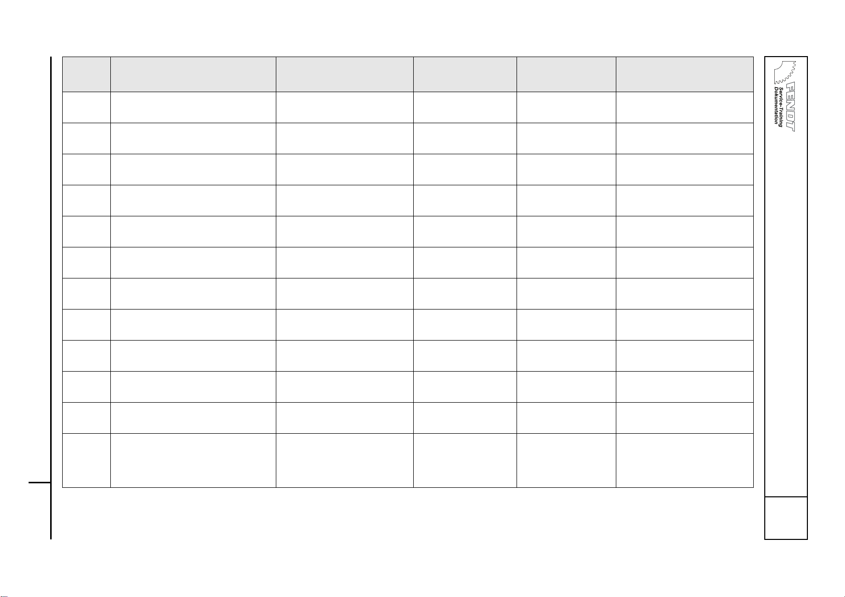
FENDT 400 Vario COM III, FENDT 700 Vario COM III, FENDT 800 Vario COM III Faults
B
OVERALL SYSTEM/TRACTOR
Fault code table COM III
400 .. 1001- 724 .. 1001- 731 .. 1001-
401 .. 1001- 725 .. 1001-
402 .. 1001- 726 .. 1001-
403 .. 1001- 727 .. 1001-
404 .. 1001- 729 .. 1001-
0000 B T000434
Ver sio n 1
20/09/2007
8
1.2.21 K063 - Heater flange relay Brake in wiring or short circuit Pre-heater inoperable Wiring diagram
Sheet 36
SERDIA (delete error)
FC:0011
1.2.22 K063 - Heater flange relay Break in wiring or incorrectly
connected
Pre-heater inoperable Wiring diagram
Sheet 36
SERDIA (delete error)
FC:0013, 0014
1.2.23 S047 - Switch, engine brake Brake in wiring or short circuit Wiring diagram
Sheet 9
SERDIA (delete error)
FC:0034
1.2.24 Y006 - Solenoid valve, engine brake Faulty valve, faulty actuation Wiring diagram
Sheet 36
SERDIA (delete error)
FC:004A
1.2.25 Y006 - Solenoid valve, engine brake Brake in wiring or short circuit Wiring diagram
Sheet 36
SERDIA (delete error)
FC:0052
1.2.27 G001 - Battery 1 (12 VDC) Short circuit to battery or
earth
Start not possible SERDIA (delete error)
FC:00B6, 00B7, 00BA, 00BC
1.2.2C K008 - Relay, starter lockout Brake in wiring or short circuit Start not possible Wiring diagram
Sheet 7
SERDIA (delete error)
FC:00DF, 00E0
1.2.30 B004 - Vacuum switch (air filter) Pressure loss above setpoint
range
Clean/replace air filter Wiring diagram
Sheet 35
SERDIA (delete error)
FC:000B, 00F2
1.2.34 S034 - Switch, coolant level Coolant outside of setpoint
level
Check coolant level Wiring diagram
Sheet 35
SERDIA (delete error)
FC:0025
1.2.37 A051 - ECU, engine control unit
(EDC 7).
Fan speed above setpoint
range
SERDIA (delete error)
1.2.3A A051 - ECU, engine control unit
(EDC 7).
Misfiring SERDIA (delete error)
FC:002F
1.2.50 Y091 - Dispensing unit (fuel) Dispensing unit not connect-
ed, short circuit to battery or
earth
Message that the engine will stop after approx. 5 minutes is
displayed
Wiring diagram
Sheet 36
SERDIA (delete error)
FC:00B0, 00B1, 00B2, 00B3
Fault
code
DIN brief description Cause Consequences Reference FENDIAS / Note
Page 71

FENDT 400 Vario COM III, FENDT 700 Vario COM III, FENDT 800 Vario COM III Faults
B
OVERALL SYSTEM/TRACTOR
Fault code table COM III
Service Training
400 .. 1001- 724 .. 1001- 731 .. 1001-
401 .. 1001- 725 .. 1001-
402 .. 1001- 726 .. 1001-
403 .. 1001- 727 .. 1001-
404 .. 1001- 729 .. 1001-
0000 B T000434
Ver sio n 1
20/09/2007
9
1.2.51 Mechanical rail pressure limiting
valve
Rail pressure limiting valve
was opened
Message that the engine will stop after approx. 5 minutes is
displayed
SERDIA (delete error)
FC:00D0, 00EC
1.2.52 B086 - Rail pressure sensor Brake in wiring or short circuit Message that the en-
gine will stop after approx. 5 minutes is
displayed
Wiring diagram
Sheet 36
SERDIA (delete error)
FC:00D1, 00D2
1.2.53 B086 - Rail pressure sensor Rail pressure outside setpoint
range
Message that the engine will stop after approx. 5 minutes is
displayed
Wiring diagram
Sheet 36
SERDIA (delete error)
FC:00D3, 00D4, 00D5, 00D6,
00D7, 00D8
1.2.54 B086 - Rail pressure sensor Rail pressure monitoring de-
activated
SERDIA (delete error)
FC:00AF
1.2.60 A051 - ECU, engine control unit
(EDC 7).
Misfiring on several cylinders SERDIA (delete error)
FC:002E
1.2.61 A051 - ECU, engine control unit
(EDC 7).
Misfiring on cylinder 1 SERDIA (delete error)
FC:0026
1.2.62 A051 - ECU, engine control unit
(EDC 7).
Misfiring on cylinder 2 SERDIA (delete error)
FC:0027
1.2.63 A051 - ECU, engine control unit
(EDC 7).
Misfiring on cylinder 3 SERDIA (delete error)
FC:0028
1.2.64 A051 - ECU, engine control unit
(EDC 7).
Misfiring on cylinder 4 SERDIA (delete error)
FC:0029
1.2.65 A051 - ECU, engine control unit
(EDC 7).
Misfiring on cylinder 5 SERDIA (delete error)
FC:002A
1.2.66 A051 - ECU, engine control unit
(EDC 7).
Misfiring on cylinder 6 SERDIA (delete error)
FC:002B
Fault
code
DIN brief description Cause Consequences Reference FENDIAS / Note
Page 72

FENDT 400 Vario COM III, FENDT 700 Vario COM III, FENDT 800 Vario COM III Faults
B
OVERALL SYSTEM/TRACTOR
Fault code table COM III
400 .. 1001- 724 .. 1001- 731 .. 1001-
401 .. 1001- 725 .. 1001-
402 .. 1001- 726 .. 1001-
403 .. 1001- 727 .. 1001-
404 .. 1001- 729 .. 1001-
0000 B T000434
Ver sio n 1
20/09/2007
10
1.2.70 A051 - ECU, engine control unit
(EDC 7).
Start of injection period in cylinder 1 outside setpoint range
or absent.
SERDIA (delete error)
FC:0018
1.2.71 A051 - ECU, engine control unit
(EDC 7).
Start of injection period in cylinder 2 outside setpoint range
or absent.
SERDIA (delete error)
FC:0019
1.2.72 A051 - ECU, engine control unit
(EDC 7).
Start of injection period in cylinder 3 outside setpoint range
or absent.
SERDIA (delete error)
FC:001A
1.2.73 A051 - ECU, engine control unit
(EDC 7).
Start of injection period in cylinder 4 outside setpoint range
or absent.
SERDIA (delete error)
FC:001B
1. 2 . 74 A051 - ECU, engine control unit
(EDC 7).
Start of injection period in cylinder 5 outside setpoint range
or absent.
SERDIA (delete error)
FC:001C
1.2.75 A051 - ECU, engine control unit
(EDC 7).
Start of injection period in cylinder 6 outside setpoint range
or absent.
SERDIA (delete error)
FC:001D
1.2.78 A051 - ECU, engine control unit
(EDC 7).
Short circuit in cylinder bank 1
injector valves
SERDIA (delete error)
FC:0099
1.2.79 A051 - ECU, engine control unit
(EDC 7).
Break in wiring of cylinder
bank 1 injector valves
SERDIA (delete error)
FC:009A
1.2.7A A051 - ECU, engine control unit
(EDC 7).
Short circuit in cylinder bank 2
injector valves
SERDIA (delete error)
FC:009B
1.2.7B A051 - ECU, engine control unit
(EDC 7).
Break in wiring of cylinder
bank 2 injector valves
SERDIA (delete error)
FC:009C
1. 2 . 7 C A051 - ECU, engine control unit
(EDC 7).
Short circuit or break in wiring
to injector valve 1
SERDIA (delete error)
FC:009F, 00A0
1.2.7D A051 - ECU, engine control unit
(EDC 7).
Short circuit or break in wiring
to injector valve 2
SERDIA (delete error)
FC:00A1, 00A2
Fault
code
DIN brief description Cause Consequences Reference FENDIAS / Note
Page 73

FENDT 400 Vario COM III, FENDT 700 Vario COM III, FENDT 800 Vario COM III Faults
B
OVERALL SYSTEM/TRACTOR
Fault code table COM III
Service Training
400 .. 1001- 724 .. 1001- 731 .. 1001-
401 .. 1001- 725 .. 1001-
402 .. 1001- 726 .. 1001-
403 .. 1001- 727 .. 1001-
404 .. 1001- 729 .. 1001-
0000 B T000434
Ver sio n 1
20/09/2007
11
1.2.7E A051 - ECU, engine control unit
(EDC 7).
Short circuit or break in wiring
to injector valve 3
SERDIA (delete error)
FC:00A3, 00A4
1.2.7F A051 - ECU, engine control unit
(EDC 7).
Short circuit or break in wiring
to injector valve 4
SERDIA (delete error)
FC:00A5, 00A6
1.2.80 A051 - ECU, engine control unit
(EDC 7).
Short circuit or break in wiring
to injector valve 5
SERDIA (delete error)
FC:00A7, 00A8
1.2.81 A051 - ECU, engine control unit
(EDC 7).
Short circuit or break in wiring
to injector valve 6
SERDIA (delete error)
FC:00A9, 00AA
1.2.90 Y094 - Actuator unit, AGR (exhaust
gas recirculation)
Short circuit to battery, earth,
break in wiring or short circuit
SERDIA (delete error)
FC:0045, 0046, 0047, 0048
1. 2 . B 0 A051 - ECU, engine control unit
(EDC 7).
CAN message, no throttle
pedal or outside setpoint
range
Wiring diagram
Sheet 36
SERDIA (delete error)
FC:005E
1. 2 . B 1 A051 - ECU, engine control unit
(EDC 7).
CAN message, no control
function mode
Wiring diagram
Sheet 36
SERDIA (delete error)
FC:005F
1. 2 . B 2 A051 - ECU, engine control unit
(EDC 7).
CAN message, no engine protection mechanism
Wiring diagram
Sheet 36
SERDIA (delete error)
FC:006A
1. 2 . B 3 A051 - ECU, engine control unit
(EDC 7).
CAN message, no pre-heater
or engine command
Wiring diagram
Sheet 36
SERDIA (delete error)
FC:006E
1. 2 . B 4 A051 - ECU, engine control unit
(EDC 7).
CAN-message missing Wiring diagram
Sheet 36
SERDIA (delete error)
FC:0070
1. 2 . B 5 A051 - ECU, engine control unit
(EDC 7).
CAN-message missing Wiring diagram
Sheet 36
SERDIA (delete error)
FC:0071
1. 2 . B 6 A051 - ECU, engine control unit
(EDC 7).
CAN-message missing Wiring diagram
Sheet 36
SERDIA (delete error)
FC:0075
Fault
code
DIN brief description Cause Consequences Reference FENDIAS / Note
Page 74

FENDT 400 Vario COM III, FENDT 700 Vario COM III, FENDT 800 Vario COM III Faults
B
OVERALL SYSTEM/TRACTOR
Fault code table COM III
400 .. 1001- 724 .. 1001- 731 .. 1001-
401 .. 1001- 725 .. 1001-
402 .. 1001- 726 .. 1001-
403 .. 1001- 727 .. 1001-
404 .. 1001- 729 .. 1001-
0000 B T000434
Ver sio n 1
20/09/2007
12
1. 2 . B 7 A051 - ECU, engine control unit
(EDC 7).
CAN-message missing Wiring diagram
Sheet 36
SERDIA (delete error)
FC:0076
1. 2 . B 8 A051 - ECU, engine control unit
(EDC 7).
CAN-message missing Wiring diagram
Sheet 36
SERDIA (delete error)
FC:0078
1. 2 . B 9 A051 - ECU, engine control unit
(EDC 7).
CAN-message missing Wiring diagram
Sheet 36
SERDIA (delete error)
FC:0079
1. 2 . B A A051 - ECU, engine control unit
(EDC 7).
CAN-message missing Wiring diagram
Sheet 36
SERDIA (delete error)
FC:007A
1. 2 . B B A051 - ECU, engine control unit
(EDC 7).
CAN-message missing Wiring diagram
Sheet 36
SERDIA (delete error)
FC:007B
1. 2 . B C A051 - ECU, engine control unit
(EDC 7).
CAN-message missing Wiring diagram
Sheet 36
SERDIA (delete error)
FC:007C
1. 2 . B D A051 - ECU, engine control unit
(EDC 7).
CAN-message missing Wiring diagram
Sheet 36
SERDIA (delete error)
FC:007D
1. 2 . B E A051 - ECU, engine control unit
(EDC 7).
CAN-message missing Wiring diagram
Sheet 36
SERDIA (delete error)
FC:007E
1. 2 . B F A051 - ECU, engine control unit
(EDC 7).
CAN-message missing Wiring diagram
Sheet 36
SERDIA (delete error)
FC:007F
1. 2 . C 0 A051 - ECU, engine control unit
(EDC 7).
CAN-message missing Wiring diagram
Sheet 36
SERDIA (delete error)
FC:0080
1. 2 . C 1 A051 - ECU, engine control unit
(EDC 7).
CAN bus times out with at
least one sent message
Wiring diagram
Sheet 36
SERDIA (delete error)
FC:0083
Fault
code
DIN brief description Cause Consequences Reference FENDIAS / Note
Page 75

FENDT 400 Vario COM III, FENDT 700 Vario COM III, FENDT 800 Vario COM III Faults
B
OVERALL SYSTEM/TRACTOR
Fault code table COM III
Service Training
400 .. 1001- 724 .. 1001- 731 .. 1001-
401 .. 1001- 725 .. 1001-
402 .. 1001- 726 .. 1001-
403 .. 1001- 727 .. 1001-
404 .. 1001- 729 .. 1001-
0000 B T000434
Ver sio n 1
20/09/2007
13
1. 2 . C 2 A051 - ECU, engine control unit
(EDC 7).
CAN bus A, break in wiring or
short circuit
Possible to drive with
foot throttle/throttle
pedal
Wiring diagram
Sheet 35
SERDIA (delete error)
FC:00C0
1. 2 . C 3 A051 - ECU, engine control unit
(EDC 7).
CAN bus B, break in wiring or
short circuit
Possible to drive with
foot throttle/throttle
pedal
Wiring diagram
Sheet 36
SERDIA (delete error)
FC:00C1
1. 2 . C 4 A051 - ECU, engine control unit
(EDC 7).
CAN bus C, break in wiring or
short circuit
Possible to drive with
foot throttle/throttle
pedal
Wiring diagram
Sheet 36
SERDIA (delete error)
FC:00C2
1. 2 . D 0 A051 - ECU, engine control unit
(EDC 7).
Faulty external pressure sensor
SERDIA (delete error)
FC:0010
1. 2 . D 1 A051 - ECU, engine control unit
(EDC 7).
Faulty engine control unit SERDIA (delete error)
FC:008D
1. 2 . D 2 A051 - ECU, engine control unit
(EDC 7).
EEPROM memory access SERDIA (delete error)
FC:008E
1. 2 . D 3 A051 - ECU, engine control unit
(EDC 7).
Injector valve (Chip)
faulty
SERDIA (delete error)
FC:009E
1. 2 . D 4 A051 - ECU, engine control unit
(EDC 7).
Injector valve (Chip)
faulty
SERDIA (delete error)
FC:009E
1. 2 . D 5 A051 - ECU, engine control unit
(EDC 7).
Faulty engine control SERDIA (delete error)
FC:00B8
1. 2 . D 6 A051 - ECU, engine control unit
(EDC 7).
Engine monitoring system
overloaded
SERDIA (delete error)
FC:00DA
1. 2 . D 7 A051 - ECU, engine control unit
(EDC 7).
Incorrect voltage for internal 5
V reference source 1
SERDIA (delete error)
FC:00DB
1. 2 . D 8 A051 - ECU, engine control unit
(EDC 7).
Incorrect voltage for internal 5
V reference source 2
SERDIA (delete error)
FC:00DD
1. 2 . D 9 A051 - ECU, engine control unit
(EDC 7).
Incorrect voltage for internal 5
V reference source 3
SERDIA (delete error)
FC:00DE
Fault
code
DIN brief description Cause Consequences Reference FENDIAS / Note
Page 76

FENDT 400 Vario COM III, FENDT 700 Vario COM III, FENDT 800 Vario COM III Faults
B
OVERALL SYSTEM/TRACTOR
Fault code table COM III
400 .. 1001- 724 .. 1001- 731 .. 1001-
401 .. 1001- 725 .. 1001-
402 .. 1001- 726 .. 1001-
403 .. 1001- 727 .. 1001-
404 .. 1001- 729 .. 1001-
0000 B T000434
Ver sio n 1
20/09/2007
14
1. 2 . D B A051 - ECU, engine control unit
(EDC 7).
Faulty serial communication
interface
SERDIA (delete error)
FC:00EB
2.1.E0 A002 - ECU, enhanced control
A034 - Driving switch, CAN bus
CAN communication between A002 and A034 faulty
Emergency operation -- check enhanced control bus
(Chapter 9000 Reg.E)
JOYSTICK
CAN - JOYSTICK
2.1.EE ISO/LBS mounted implement ISO/LBS job computer failed Mounted implement
can no longer be operated via joystick
controls or terminal.
For fault description,
please refer to implement manufacturer's
documentation
2.1.EF ISO/LBS mounted implement ISO/LBS job computer failed Restricted operation
of mounted implement, depending on
manufacturer
For fault description,
please refer to implement manufacturer's
documentation
3.1.01 A004 - ECU, control panel Internal RAM, EEPROM faults Functions switched
off:
– Keypad, - digital /
analogue inputs,
– LED actuation
Replace control panel
3.1.02 A004 - ECU, control panel Internal RAM, EEPROM faults Functions switched
off:
– Keypad, - digital /
analogue inputs,
- LED actuation
Replace control panel
3.1.03 A004 - ECU, control panel Internal RAM, EEPROM faults Functions switched
off:
– Keypad, - digital /
analogue inputs,
- LED actuation
Replace control panel
Fault
code
DIN brief description Cause Consequences Reference FENDIAS / Note
Page 77

FENDT 400 Vario COM III, FENDT 700 Vario COM III, FENDT 800 Vario COM III Faults
B
OVERALL SYSTEM/TRACTOR
Fault code table COM III
Service Training
400 .. 1001- 724 .. 1001- 731 .. 1001-
401 .. 1001- 725 .. 1001-
402 .. 1001- 726 .. 1001-
403 .. 1001- 727 .. 1001-
404 .. 1001- 729 .. 1001-
0000 B T000434
Ver sio n 1
20/09/2007
15
3.1.04 A004 - ECU, control panel Internal RAM, EEPROM faults Functions switched
off:
– Keypad, - digital /
analogue inputs,
- LED actuation
Replace control panel
3.1.05 A004 - ECU, control panel Internal 8.5 V fault, keypad
fault
Functions switched
off:
– Keypad, - digital /
analogue inputs,
- LED actuation
Replace control panel
3.1.06 A004 - ECU, control panel External 8.5 V fault Functions switched
off:
– Keypad, - digital /
analogue inputs,
- LED actuation
Replace control panel
4.1.03 Neumaier reversing system – clutch
pedal potentiometer
Signal fault Continuation in emer-
gency mode possible
(Neumaier service manual)
Calibration code "4011"
Faulty 8.5 V supply A013 fuse 9
4.1.04 B017 - Sensor, clutch pedal Signal fault Loss of enhanced
control/function in final speed control; no
Tempomat cruise
control function, TMS
is switched off
Wiring diagram
Sheet 29
TRANSMISSION
TRAVEL RANGE
Faulty 8.5 V supply A013 fuse 8
4.1.05 B039 - Sensor, high-pressure 2 Signal fault Loss of enhanced
control functions in
operating mode (no
"active hold function")
Wiring diagram
Sheet 29
TRANSMISSION
TURBO CLUTCH
12 V supply fault A013 fuse 2
Fault
code
DIN brief description Cause Consequences Reference FENDIAS / Note
Page 78

FENDT 400 Vario COM III, FENDT 700 Vario COM III, FENDT 800 Vario COM III Faults
B
OVERALL SYSTEM/TRACTOR
Fault code table COM III
400 .. 1001- 724 .. 1001- 731 .. 1001-
401 .. 1001- 725 .. 1001-
402 .. 1001- 726 .. 1001-
403 .. 1001- 727 .. 1001-
404 .. 1001- 729 .. 1001-
0000 B T000434
Ver sio n 1
20/09/2007
16
4.1.06 B055 - Sensor, foot throttle Signal fault Restricted operation
(no hand throttle, no
memory keys)
Wiring diagram
Sheet 35
TRANSMISSION
LOAD LIMIT CONTROL
Faulty 8.5 V supply A013 fuse 17
4.1.07 B008 - Sensor, high-pressure 1 Signal fault Travel range switch-
ing from 1 to 2 not
possible, TMS
switched off
Wiring diagram
Sheet 29
TRANSMISSION
TURBO CLUTCH
Faulty 8.5 V supply A013 fuse 3
4.1.08 B016 - Sensor, travel range detection
Signal fault Travel range switch-
ing not possible; current travel range is
retained
Wiring diagram
Sheet 29
TRANSMISSION
TRAVEL RANGE
Faulty 8.5 V supply A013 fuse 13
4.1.20 A002 - ECU, enhanced control Accelerator pedal release po-
tentiometer ("slide switch")
not calibrated or EEPROM
checksum error
Driving in accelerator
pedal mode not possible
JOYSTICK
CAN - JOYSTICK
Calibration code "4010"
4.1.22 A034 - Driving switch, CAN bus Accelerator pedal release po-
tentiometer ("slide switch")
faulty
Throttle pedal mode
inoperable
JOYSTICK
CAN - JOYSTICK
4.1.23 A034 - Driving switch, CAN bus Signal fault
("Tempomat cruise control
on")
Continuation in emergency mode possible
Wiring diagram
Sheet 29
TRANSMISSION, CRUISE
CONTROL
4.1.25 A034 - Driving switch, CAN bus Signal fault
("Quick reverse")
Continuation in emergency mode possible
Wiring diagram
Sheet 29
TRANSMISSION
man. ADJUSTMENT
4.1.26 A034 - Driving switch, CAN bus Driving switch signal "throttle
pedal mode" faulty
Throttle pedal mode
inoperable
JOYSTICK
CAN - JOYSTICK
Fault
code
DIN brief description Cause Consequences Reference FENDIAS / Note
Page 79
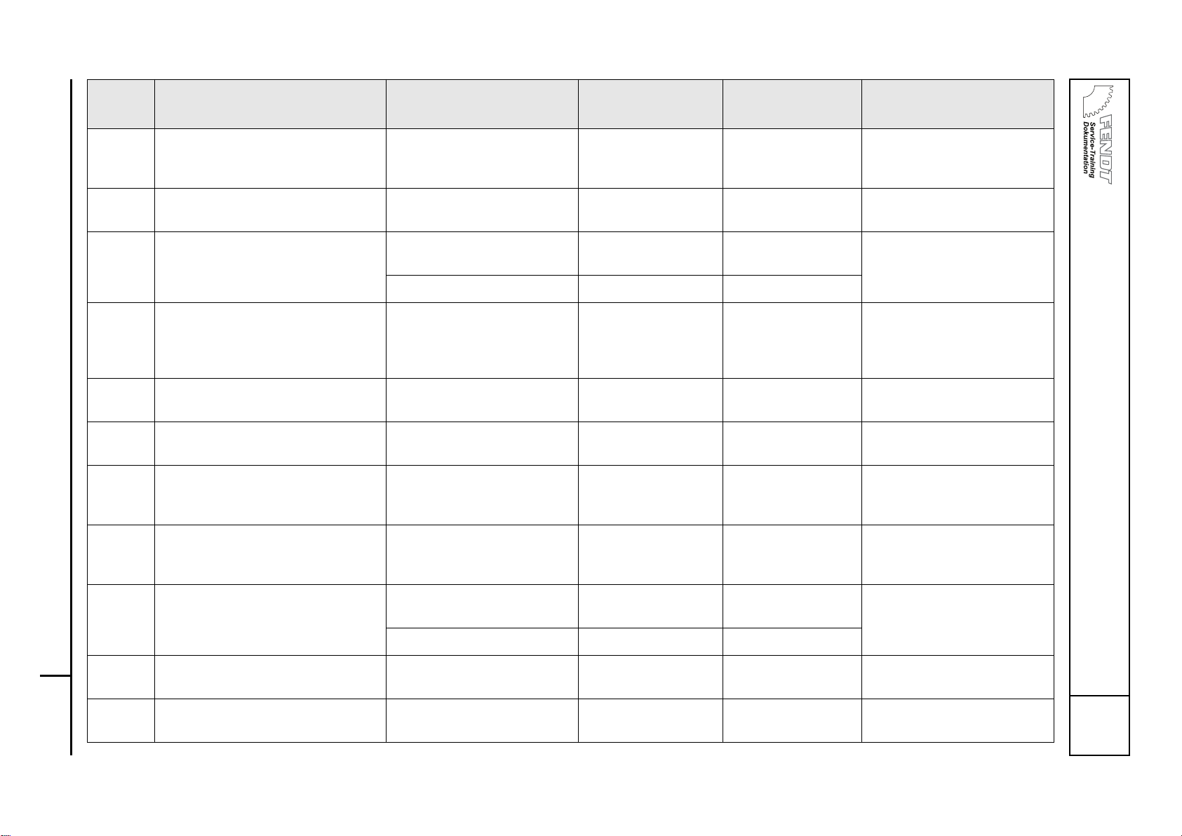
FENDT 400 Vario COM III, FENDT 700 Vario COM III, FENDT 800 Vario COM III Faults
B
OVERALL SYSTEM/TRACTOR
Fault code table COM III
Service Training
400 .. 1001- 724 .. 1001- 731 .. 1001-
401 .. 1001- 725 .. 1001-
402 .. 1001- 726 .. 1001-
403 .. 1001- 727 .. 1001-
404 .. 1001- 729 .. 1001-
0000 B T000434
Ver sio n 1
20/09/2007
17
4.1.28 A009 - Actuator unit
VR incremental encoder
Signal fault Continuation in emer-
gency mode possible
Wiring diagram
Sheet 29
TRANSMISSION
TRANSMISSION ADJUSTMENT
4.1.29 A034 - Driving switch, CAN bus joy-
stick "centre position"
Signal fault Continuation in emer-
gency mode possible
Wiring diagram
Sheet 29
JOYSTICK
CAN - JOYSTICK
4.1.2A B015 - Sensor, bevel pinion (= travel
direction)
Signal fault Continuation in emer-
gency mode possible
Wiring diagram
Sheet 29
TRANSMISSION, CRUISE
CONTROL
Faulty 8.5 V supply A013 fuse 7
4.1.2B A034 - Driving switch, CAN bus Signal fault Current travel range
remains applied; further switching not
possible
Wiring diagram
Sheet 29
JOYSTICK
CAN - JOYSTICK
4.1.2C A034 - Driving switch, CAN bus Signal fault Continuation in emer-
gency mode possible
Wiring diagram
Sheet 29
JOYSTICK
CAN - JOYSTICK
4.1.2D S061 - Switch, quick reverse Signal fault Quick reverse still
possible via joystick
Wiring diagram
Sheet 29
JOYSTICK
CAN - JOYSTICK
4.1.2E A034 - Driving switch, CAN bus "v+ transmission adjustment"
(joystick forwards)
Signal fault
Continuation in emergency mode possible
Wiring diagram
Sheet 29
JOYSTICK
CAN - JOYSTICK
4.1.2F A034 - Driving switch, CAN bus "v- transmission adjustment"
(joystick to rear)
Signal fault
Continuation in emergency mode possible
Wiring diagram
Sheet 29
JOYSTICK
CAN - JOYSTICK
4.1.31 B014 - Sensor, hydrostatic collecting shaft (= travel direction)
Signal fault Continuation in emer-
gency mode possible
Wiring diagram
Sheet 29
TRANSMISSION
TEMPOMAT cruise control
Faulty 8.5 V supply A013 fuse 16
4.1.32 A034 - Driving switch, CAN bus "Activation button" on joystick
Signal fault
Continuation in emergency mode possible
Wiring diagram
Sheet 29
JOYSTICK
CAN - JOYSTICK
4.1.42 B014
- Sensor, hydrostatic collect-
ing shaft (= RPM)
Signal fault Continuation in emer-
gency mode possible
Wiring diagram
Sheet 29
TRANSMISSION, CRUISE
CONTROL
Fault
code
DIN brief description Cause Consequences Reference FENDIAS / Note
Page 80

FENDT 400 Vario COM III, FENDT 700 Vario COM III, FENDT 800 Vario COM III Faults
B
OVERALL SYSTEM/TRACTOR
Fault code table COM III
400 .. 1001- 724 .. 1001- 731 .. 1001-
401 .. 1001- 725 .. 1001-
402 .. 1001- 726 .. 1001-
403 .. 1001- 727 .. 1001-
404 .. 1001- 729 .. 1001-
0000 B T000434
Ver sio n 1
20/09/2007
18
Faulty 8.5 V supply A013 fuse 16
4.1.44 B010 - Sensor, engine speed Signal fault Continuation in emer-
gency mode possible
Wiring diagram
Sheet 29
TRANSMISSION, CRUISE
CONTROL
12 V supply fault A013 fuse 4
4.1.45 B015 - Sensor, bevel pinion (= travel
speed)
Signal fault Continuation in emer-
gency mode possible
Wiring diagram
Sheet 29
TRANSMISSION
TEMPOMAT cruise control
Faulty 8.5 V supply A013 fuse 7
4.1.50 S017 - Switch, transmission oil contamination
Filter clogged No further indication
of clogging
Wiring diagram
Sheet 29
TRANSMISSION
TRANSMISSION OIL/FILTER
switch function inactive below oil temperature of 50°C
4.1.53 B009 - Discharge temperature "Transmission oil temperature
above 110°C"
transmission damage if journey is continued!
Wiring diagram
Sheet 29
TRANSMISSION
TRANSMISSION OIL/FILTER
4.1.58 Transmission slip monitor Transmission output speed
deviates by more than 30%
from setpoint value
May occur at extremely low temperatures in isolated
cases; repeated occurrence under normal conditions
causes a rise in oil
temperature and further transmission
damage; TMS is
switched off
Fault not active
when turbo-clutch
(TC) function is on –
clutch depressed,
TRANSMISSION
TRANSMISSION ADJUSTMENT
(Comparison "ideal gear ratio /
actual gear ratio")
4.1.59 "Emergency operation" actuation Emergency operation activat-
ed manually without apparent
reason
Fault code is not stored
Fault in emergency mode
4.1.61 Y002 - Solenoid valve, travel range I
"switching from travel range 2 - 1"
Actuation fault Continuation in emer-
gency mode possible
Wiring diagram
Sheet 29
TRANSMISSION
TRAVEL RANGE
Fault
code
DIN brief description Cause Consequences Reference FENDIAS / Note
Page 81

FENDT 400 Vario COM III, FENDT 700 Vario COM III, FENDT 800 Vario COM III Faults
B
OVERALL SYSTEM/TRACTOR
Fault code table COM III
Service Training
400 .. 1001- 724 .. 1001- 731 .. 1001-
401 .. 1001- 725 .. 1001-
402 .. 1001- 726 .. 1001-
403 .. 1001- 727 .. 1001-
404 .. 1001- 729 .. 1001-
0000 B T000434
Ver sio n 1
20/09/2007
19
4.1.62 Y003 - Solenoid valve, travel range
II "switching from travel range 1 – 2"
Actuation fault Continuation in emer-
gency mode possible
TRANSMISSION
TRAVEL RANGE
4.1.63 Y005 - Solenoid valve, speed governor (= restriction of actuator shaft rotation angle)
Actuation fault Possible to continue
at max. 30 km/h
Wiring diagram
Sheet 29
TRANSMISSION
FUNCTIONAL OVERVIEW
4.1.64 Y004 - Solenoid valve, turbo-clutch PWM actuation fault Wiring diagram
Sheet 29
TRANSMISSION
TURBO CLUTCH
4.1.65 Y053 - Active hold function solenoid valve
Actuation fault No active hold func-
tion
Wiring diagram
Engine brake – stationary control
TRANSMISSION
FUNCTIONAL OVERVIEW
4.1.66 K051 - Relay, active hold function
Y053 - Active hold function solenoid valve
Relay faulty, solenoid valve
faulty, signal line faulty
No active hold function
Wiring diagram
Engine brake – stationary control
TRANSMISSION
FUNCTIONAL OVERVIEW
4.1.67 K051 - Relay, active hold function Relay test unsuccessful, relay
contacts (pin 3 / 5) stuck.
No active hold function
Wiring diagram
Engine brake and active hold function
TRANSMISSION
FUNCTIONAL OVERVIEW
4.1.68 A002 - ECU, enhanced control
A009 - Actuator unit
Transmission characteristic
shifted in neutral point
TRANSMISSION CALIBRATION
4.1.70 A004 - ECU, control panel Faulty button
"Tempomat cruise control 1"
button
Tempomat cruise
control cannot be activated
Wiring diagram
Sheet 29
TRANSMISSION
TEMPOMAT cruise control
4.1.71 A004 - ECU, control panel Faulty button
"Tempomat cruise control 2"
button
Tempomat cruise
control cannot be activated
Wiring diagram
Sheet 29
TRANSMISSION
TEMPOMAT cruise control
4.1.72 S017 - Switch, transmission oil contamination
Signal fault No further display or
monitoring, possibly
transmission damage
Wiring diagram
Sheet 29
TRANSMISSION
TRANSMISSION OIL/FILTER
4.1.73 B009 - Discharge temperature Signal fault No further display or
monitoring, possibly
transmission damage
Wiring diagram
Sheet 29
TRANSMISSION
TRANSMISSION OIL/FILTER
Fault
code
DIN brief description Cause Consequences Reference FENDIAS / Note
Page 82

FENDT 400 Vario COM III, FENDT 700 Vario COM III, FENDT 800 Vario COM III Faults
B
OVERALL SYSTEM/TRACTOR
Fault code table COM III
400 .. 1001- 724 .. 1001- 731 .. 1001-
401 .. 1001- 725 .. 1001-
402 .. 1001- 726 .. 1001-
403 .. 1001- 727 .. 1001-
404 .. 1001- 729 .. 1001-
0000 B T000434
Ver sio n 1
20/09/2007
20
4 . 1. 74 S015 - Switch, hand brake
"OPEN/CLOSED" detection
Signal fault TMS is switched off Wiring diagram
Sheet 29
TRANSMISSION
man. ADJUSTMENT
4.1.76 S047 - Switch, engine brake Signal fault TMS is switched off Wiring diagram
Sheet 29
TRANSMISSION
TEMPOMAT cruise control
4.1.77 A034 - Driving switch, CAN bus Acceleration ramp I ... IV
switch faulty
Only acceleration rate
III available
JOYSTICK
CAN - JOYSTICK
4.1.78 S053 - Switch, driver seat Signal from seat switch faulty Selection of direction
of travel is disabled in
accelerator pedal
mode when vehicle is
stationary (the driver
must re-activate the
selection of direction
of travel)
TRANSMISSION
man. ADJUSTMENT
4.1.82 B014 - Sensor, hydrostatic collecting shaft
B015 - Sensor, bevel pinion
B016 - Sensor, travel range detec-
tion
Plausibility error (=speeds do
not match)
Continuation in emergency mode possible
Wiring diagram
Sheet 29
TRANSMISSION
TEMPOMAT cruise control
4.1.83 B014 - Sensor, hydrostatic collecting shaft
B015 - Sensor, bevel pinion
Plausibility error (=speeds do
not match)
Continuation in emergency mode possible
Wiring diagram
Sheet 29
TRANSMISSION
TEMPOMAT cruise control
4.1.84 A034 - Driving switch, CAN bus Plausibility error (F, R, FR,
Tempomat cruise control, default positions do not match)
Continuation in emergency mode possible
Wiring diagram
Sheet 29
JOYSTICK
CAN - JOYSTICK
4.1.85 B010 - Sensor, engine speed Engine speed sensor does
not report plausible speed
curves. Output speed increase or decrease outside
limits.
Continuation in emergency mode possible
Wiring diagram
Sheet 29
TRANSMISSION
LOAD LIMIT CONTROL
Fault
code
DIN brief description Cause Consequences Reference FENDIAS / Note
Page 83

FENDT 400 Vario COM III, FENDT 700 Vario COM III, FENDT 800 Vario COM III Faults
B
OVERALL SYSTEM/TRACTOR
Fault code table COM III
Service Training
400 .. 1001- 724 .. 1001- 731 .. 1001-
401 .. 1001- 725 .. 1001-
402 .. 1001- 726 .. 1001-
403 .. 1001- 727 .. 1001-
404 .. 1001- 729 .. 1001-
0000 B T000434
Ver sio n 1
20/09/2007
21
4.1.86 B008 - Sensor, high-pressure 1
B039 - Sensor, high-pressure 2
Plausibility error between
B008 sensor (transmission
drive pressure) and B039 sensor (push detection)
Loss of enhanced
control when driving
("no active hold function"), TMS switched
off
TRANSMISSION
TEMPOMAT cruise control
4.1.87 S061 - Switch, quick reverse Plausibility error at VR switch,
quick reverse
VR switch inoperable,
quick reverse on
steering wheel adjustment lever, S061
switch,
Check quick reverse
Chapter 9000 Reg. E
TRANSMISSION
man. ADJUSTMENT
4.1.88 A034 - Driving switch, CAN bus Plausibility error at the ON/
OFF button of the accelerator
pedal mode
Button not functioning
JOYSTICK
CAN - JOYSTICK
4.1.89 B009 - Discharge temperature Plausibility error, transmission
temperature
Sensor or wiring
faulty
TRANSMISSION
TRANSMISSION OIL/FILTER
4.1.94 A034 - Driving switch, CAN bus CAN communication fault be-
tween A002 ECU, enhanced
control and A034 joystick
Driving switch functions limited.
JOYSTICK
CAN - JOYSTICK
4.1.A1 A009 - Actuator unit Turn angle is not reached
within 2 seconds.
Continuation in emergency mode possible
Mechanical check:
check smooth adjustment action in
emergency mode.
TRANSMISSION
TRANSMISSION ADJUSTMENT
4.1.A2 A009 - Actuator unit CAN bus actuation fault Continuation in emer-
gency mode possible
Check CAN bus,
Chapter 9000 Reg. E
TRANSMISSION
TRANSMISSION ADJUSTMENT
4.1.A3 A009 - Actuator unit Fault or logic error in incre-
mental sensor signal (actual
position signal)
Continuation in emergency mode possible
TRANSMISSION
TRANSMISSION ADJUSTMENT
4.1.A4 A009 - Actuator unit Fault or logical error in EST
signal.
Continuation in emergency mode possible
TRANSMISSION
TRANSMISSION ADJUSTMENT
Fault
code
DIN brief description Cause Consequences Reference FENDIAS / Note
Page 84

FENDT 400 Vario COM III, FENDT 700 Vario COM III, FENDT 800 Vario COM III Faults
B
OVERALL SYSTEM/TRACTOR
Fault code table COM III
400 .. 1001- 724 .. 1001- 731 .. 1001-
401 .. 1001- 725 .. 1001-
402 .. 1001- 726 .. 1001-
403 .. 1001- 727 .. 1001-
404 .. 1001- 729 .. 1001-
0000 B T000434
Ver sio n 1
20/09/2007
22
4.1.A5 A009 - Actuator unit Initial reference (=zero posi-
tion) could not be found during ignition ON
Continuation in emergency mode possible
TRANSMISSION
TRANSMISSION ADJUSTMENT
4.1.A6 A009 - Actuator unit Reference point signal fault
during operation
Continuation in emergency mode possible
TRANSMISSION
TRANSMISSION ADJUSTMENT
4.1.B0 All bus users Initialisation error Restricted CAN bus
data communication
Check CAN bus,
Chapter 9000 Reg. E
EOL programming
4.1.B2 A002 - ECU, enhanced control Fault in EPROM programming
(travel range selector I/II)
Range cannot be
changed while driving.
EOL programming
4.1.B3 A002 - ECU, enhanced control Fault in EPROM programming
(quick reverse rate parameters)
Quick reversing possible with standard
values.
EOL programming
4.1.B4 B010 - Sensor, engine speed Input parameter values for
plausibility monitoring are incorrect.
Standard parameters
are stored, plausibility
monitoring system
remains functional.
EOL programming
4.1.B5 A002 - ECU, enhanced control Checksum error rate parame-
ters, quick reverse for Tractor
Management System (TMS)
EOL programming
4.1.B6 "Neumaier reversing system" equipment
Neumaier reversing system
control failed or faulty
(Neumaier service manual)
4.1.E0 Y004 - Solenoid valve, turbo-clutch Wrong characteristic stored Continuation in emer-
gency mode possible
Calibration code "4009"
4.1.E1 A002 - ECU, enhanced control Pressure regulator control pa-
rameters in tractive power
control (ML transmission adjustment) not plausible or
read incorrectly
EOL programming
Fault
code
DIN brief description Cause Consequences Reference FENDIAS / Note
Page 85

FENDT 400 Vario COM III, FENDT 700 Vario COM III, FENDT 800 Vario COM III Faults
B
OVERALL SYSTEM/TRACTOR
Fault code table COM III
Service Training
400 .. 1001- 724 .. 1001- 731 .. 1001-
401 .. 1001- 725 .. 1001-
402 .. 1001- 726 .. 1001-
403 .. 1001- 727 .. 1001-
404 .. 1001- 729 .. 1001-
0000 B T000434
Ver sio n 1
20/09/2007
23
4.1.E2 A002 - ECU, enhanced control Pressure regulator control pa-
rameters in tractive power
control not plausible (B008/
B039) or read incorrectly.
EOL programming
4.1.E3 A002 - ECU, enhanced control Checksum error, parameter
for throttle pedal mode
TMS is switched off EOL programming
4.1.E4 A002 - ECU, enhanced control Checksum error for active
hold function parameters
EOL programming
4.1.E5 A002 - ECU, enhanced control Checksum error for range
control parameters
EOL programming
4.1.E6 A002 - ECU, enhanced control Checksum error for load limit
control parameters
EOL programming
4.1.E7 A002 - ECU, enhanced control Checksum error for joystick
parameters
EOL programming
4.1.E8 "Neumaier reversing system" equipment
Checksum error in clutch pedal potentiometer on Neumaier
reversing system, or clutch
calibration faulty
(Neumaier service manual)
Calibration code "4011"
4.1.E9 A002 - ECU, enhanced control Values for shift from range II
to I outside tolerance
Shifting only possible
when stationary
Calibration code "4003"
4.1.EA A002 - ECU, enhanced control Internal fault (RAM/EEPROM) Continuation in emer-
gency mode possible
EOL programming
4.1.EB B016 - Sensor, travel range detec-
tion
No calibration or drifted, altered values
Continuation in emergency mode possible
TRANSMISSION
TRAVEL RANGE
Calibration code "4003"
4.1.EC B055 - Sensor, foot throttle No calibration or drifted, al-
tered values
Continuation in emergency mode possible
TRANSMISSION, LOAD LIMIT CONTROL, calibration code
"4005"
Fault
code
DIN brief description Cause Consequences Reference FENDIAS / Note
Page 86

FENDT 400 Vario COM III, FENDT 700 Vario COM III, FENDT 800 Vario COM III Faults
B
OVERALL SYSTEM/TRACTOR
Fault code table COM III
400 .. 1001- 724 .. 1001- 731 .. 1001-
401 .. 1001- 725 .. 1001-
402 .. 1001- 726 .. 1001-
403 .. 1001- 727 .. 1001-
404 .. 1001- 729 .. 1001-
0000 B T000434
Ver sio n 1
20/09/2007
24
4.1.ED B017 - Sensor, clutch pedal No calibration or drifted, al-
tered values
Continuation in emergency mode possible
TRANSMISSION
TRAVEL RANGE
Calibration code "4001"
4.1.EE A002 - ECU, enhanced control No calibration or drifted, al-
tered values
Continuation in emergency mode possible
TRANSMISSION
TRANSMISSION ADJUSTMENT
Calibration code "4007"
4.1.EF A002 - ECU, enhanced control No calibration or drifted, al-
tered values
Continuation in emergency mode possible
TRANSMISSION
TURBO CLUTCH
Calibration code "4009"
4.1.F0 A002 - ECU, enhanced control Incorrect checksum for trans-
mission calibration parameters
Transmission calibration not possible
EOL programming
4.1.FF A002 - ECU, enhanced control Internal fault (RAM/EEPROM) Continuation in emer-
gency mode possible
EOL programming
5.1.00 A002 - ECU, enhanced control EEPROM checksum error EOL programming
5.1.31 A004 - ECU, control panel
4WD 100% button
Faulty signal, button/A004 Other functions re-
main active
Wiring diagram
Sheet 33
ENHANCED CONTROL
4WD
5.1.32 A004 - ECU, control panel
Auto 4WD button
Faulty signal, button/A004 Other functions re-
main active
Wiring diagram
Sheet 33
ENHANCED CONTROL
4WD
5.1.33 Y009 - Solenoid valve, 4WD Actuation fault 4WD engages Wiring diagram
Sheet 33
ENHANCED CONTROL
4WD
5.1.34 B094 - Sensor, steering angle (4WD
differential lock)
Signal/switch fault 4WD/differential lock
auto system inoperable
Wiring diagram
Sheet 33
ENHANCED CONTROL
4WD
5.1.35 B094 - Sensor, steering angle (4WD
differential lock)
Signal/switch fault 4WD/differential lock
auto system inoperable
Wiring diagram
Sheet 33
ENHANCED CONTROL
4WD
5.1.51 A004 - ECU, control panel
Differential lock 100% button
Faulty signal, button/A004 Other functions re-
main active
Wiring diagram
Sheet 33
ENHANCED CONTROL
DIFFERENTIAL LOCK
Fault
code
DIN brief description Cause Consequences Reference FENDIAS / Note
Page 87

FENDT 400 Vario COM III, FENDT 700 Vario COM III, FENDT 800 Vario COM III Faults
B
OVERALL SYSTEM/TRACTOR
Fault code table COM III
Service Training
400 .. 1001- 724 .. 1001- 731 .. 1001-
401 .. 1001- 725 .. 1001-
402 .. 1001- 726 .. 1001-
403 .. 1001- 727 .. 1001-
404 .. 1001- 729 .. 1001-
0000 B T000434
Ver sio n 1
20/09/2007
25
5.1.52 A004 - ECU, control panel
Differential lock auto system button
Faulty signal, button/A004 Other functions re-
main active
Wiring diagram
Sheet 33
ENHANCED CONTROL
DIFFERENTIAL LOCK
5.1.53 Y010 - Solenoid valve, differential
lock (rear)
Actuation fault Differential lock dis-
engages
Wiring diagram
Sheet 33
ENHANCED CONTROL
DIFFERENTIAL LOCK
5.1.54 S006 - Switch, left brake Signal fault Differential lock auto
system no longer
available, TMS
switched off
Wiring diagram
Sheet 33
ENHANCED CONTROL
DIFFERENTIAL LOCK
5.1.55 S005 - Switch, right brake Signal fault Differential lock auto
system no longer
available, TMS
switched off
Wiring diagram
Sheet 33
ENHANCED CONTROL
DIFFERENTIAL LOCK
5.1.61 B003 - Sensor, front axle suspension position
Signal fault No further functionali-
ty, suspension remains in last position.
Further travel without
suspension possible
Wiring diagram
Sheet 31
ENHANCED CONTROL
SUSPENSION
Faulty 8.5 V supply A013 fuse 18
5.1.62 Y014 - Raise suspension solenoid
valve
12 V actuation faulty No further functionali-
ty, suspension remains in last position.
Further travel without
suspension possible
Wiring diagram
Sheet 31
ENHANCED CONTROL SUSPENSION
5.1.63 Y013 - Pressure cut-off valve, suspension
12 V actuation faulty No further functionali-
ty, suspension remains in last position.
Further travel without
suspension possible
Wiring diagram
Sheet 31
ENHANCED CONTROL
SUSPENSION
5.1.64 A004 - ECU, control panel
"Suspension ON" button
Fault in signal from button to
A004
Suspension not operational. Further travel
without suspension
possible
ENHANCED CONTROL
SUSPENSION
Fault
code
DIN brief description Cause Consequences Reference FENDIAS / Note
Page 88

FENDT 400 Vario COM III, FENDT 700 Vario COM III, FENDT 800 Vario COM III Faults
B
OVERALL SYSTEM/TRACTOR
Fault code table COM III
400 .. 1001- 724 .. 1001- 731 .. 1001-
401 .. 1001- 725 .. 1001-
402 .. 1001- 726 .. 1001-
403 .. 1001- 727 .. 1001-
404 .. 1001- 729 .. 1001-
0000 B T000434
Ver sio n 1
20/09/2007
26
5.1.65 A004 - ECU, control panel
"Suspension OFF/Lock" button
Fault in signal from button to
A004
Suspension not operational. Further travel
without suspension
possible
ENHANCED CONTROL
SUSPENSION
5.1.6E B003 - Sensor, front axle suspension position
Incorrect calibration Suspension not oper-
ational
ENHANCED CONTROL
SUSPENSION
Calibration code "7666"
5.1.8D A002 - ECU, enhanced control Checksum error old config.
data
Limited enhanced
control operation
EOL programming
5.1.8F A002 - ECU, enhanced control Checksum error old auto sys-
tem sequence data
Limited enhanced
control operation
EOL programming
5.1.91 A034 - Driving switch, CAN bus Signal fault from "Rear auto-
matic system ON/OFF" button
on joystick
Rear automatic system not functioning
JOYSTICK
5.1.93 A034 - Driving switch, CAN bus Signal fault from "Front auto-
matic system ON/OFF" button
on joystick
Front automatic system not functioning
JOYSTICK
5.1.95 A034 - Driving switch, CAN bus Signal fault from "Automatic
function STOP" button on joystick
Automatic stop not
functioning
REAR EPC ACTUATION; JOYSTICK
5.1.98 S025 - Switch, LS pump pressure
monitor
Minimum pressure not
reached
Valves may lock or
flow may be reduced
Wiring diagram
Sheet 26
See also Chapter
9000 Reg. E
Fault code only after min. 1
second > 1000 rpm
5.1.99 S026 - Switch, steering pump flow
controller
Minimum flow not reached Control valve flow au-
tomatically reduced
to 20 l/min.
Wiring diagram
Sheet 26
See also Chapter
9000 Reg. E
Fault code only after min. 1
second > 1000 rpm
Fault
code
DIN brief description Cause Consequences Reference FENDIAS / Note
Page 89

FENDT 400 Vario COM III, FENDT 700 Vario COM III, FENDT 800 Vario COM III Faults
B
OVERALL SYSTEM/TRACTOR
Fault code table COM III
Service Training
400 .. 1001- 724 .. 1001- 731 .. 1001-
401 .. 1001- 725 .. 1001-
402 .. 1001- 726 .. 1001-
403 .. 1001- 727 .. 1001-
404 .. 1001- 729 .. 1001-
0000 B T000434
Ver sio n 1
20/09/2007
27
5.1.9A S026 - Switch, steering pump flow
controller
Switch faulty (no longer closes/remains open even without oil flow)
Plausibility error (incorrect voltage value/
Ohm value)
Wiring diagram
Sheet 26
See also Chapter
9000 Reg. E
Fault code appears 8 seconds
after "Ignition ON". Error message can be acknowledged,
but reappears after 10 minutes.
5.1.9B S025 - Switch, LS pump pressure
monitor
Faulty pressure switch No monitoring Wiring diagram
Sheet 26
See also Chapter
9000 Reg. E
Fault code with engine running
5.1.9D B091 - Sensor, water in fuel Water in fuel Drain container Wiring diagram
Sheet 36
5.1.9E S034 - Switch, coolant level Level too low Engine damage! Wiring diagram
Sheet 24
Error message can be cleared
only temporarily; it is repeated
every 2 minutes
5.1.9F S034 - Switch, coolant level Signal fault No further monitoring Wiring diagram
Sheet 24
5.1.B0 A002 - ECU, enhanced control CAN bus communication re-
stricted
EOL programming
5.1.FD A002 - ECU, enhanced control CAN3 component could not
be initialised
ISO bus may not be
fully functioning
5.1.FF A002 - ECU, enhanced control Internal fault (RAM/EEPROM) EOL programming
6.1.01 A004 - ECU, control panel
Rear PTO button in cab ON/OFF
Signal fault, button/A004 PTO disengages Wiring diagram
Sheet 32
ENHANCED CONTROL
REAR PTO
6.1.02 S020 - Switch (external), rear right
PTO
Signal fault PTO can be engaged
by pressing emergency button in cab for 5
seconds
Wiring diagram
Sheet 32
ENHANCED CONTROL
REAR PTO
6.1.03 S019 - Switch (external), rear left
PTO
Signal fault PTO can be engaged
by pressing emergency button in cab for 5
seconds
Wiring diagram
Sheet 32
ENHANCED CONTROL
REAR PTO
Fault
code
DIN brief description Cause Consequences Reference FENDIAS / Note
Page 90

FENDT 400 Vario COM III, FENDT 700 Vario COM III, FENDT 800 Vario COM III Faults
B
OVERALL SYSTEM/TRACTOR
Fault code table COM III
400 .. 1001- 724 .. 1001- 731 .. 1001-
401 .. 1001- 725 .. 1001-
402 .. 1001- 726 .. 1001-
403 .. 1001- 727 .. 1001-
404 .. 1001- 729 .. 1001-
0000 B T000434
Ver sio n 1
20/09/2007
28
6.1.04 Y008 - Solenoid valve, rear PTO
(clutch)
Actuation fault PTO disengages Wiring diagram
Sheet 32
ENHANCED CONTROL
REAR PTO
6.1.05 B021 - Sensor, rear PTO speed
(clutch)
Signal fault PTO can be engaged
by pressing emergency button in cab for 5
seconds
Wiring diagram
Sheet 32
ENHANCED CONTROL
REAR PTO
12 V supply fault A013 fuse 33
6.1.0A A004 - ECU, control panel "Active"
button (only NA version)
Button signal fault PTO cannot be en-
gaged
ENHANCED CONTROL
REAR PTO
6.1.10 B020 - Sensor, rear PTO speed
(stub shaft)
Signal fault PTO can be engaged
by pressing emergency button in cab for 5
seconds
Wiring diagram
Sheet 32
ENHANCED CONTROL
REAR PTO
12 V supply fault A013 fuse 32
6.1.11 A004 - ECU, control panel
Rear PTO auto mode button
Signal fault PTO disengages, au-
tomatic mode OFF
Wiring diagram
Sheet 32
ENHANCED CONTROL
REAR PTO
6.1.15 A004 - ECU, control panel
Speed selector button NEUTRAL
Button signal fault PTO speed cannot be
modified or selected
Wiring diagram
Sheet 32
ENHANCED CONTROL
REAR PTO
6.1.16 A004 - ECU, control panel
Speed selector button 540 rpm
Button signal fault PTO speed cannot be
modified or selected
Wiring diagram
Sheet 32
ENHANCED CONTROL
REAR PTO
6.1.17 A004 - ECU, control panel
Speed selector button 750 rpm
Button signal fault PTO speed cannot be
modified or selected
Wiring diagram
Sheet 32
ENHANCED CONTROL
REAR PTO
6.1.18 A004 - ECU, control panel
Speed selector key 1000 rpm
Button signal fault PTO speed cannot be
modified or selected
Wiring diagram
Sheet 32
ENHANCED CONTROL
REAR PTO
6.1.1A Y026 - Solenoid valve, rear PTO,
stage I
Actuation fault PTO cannot be en-
gaged
Wiring diagram
Sheet 32
ENHANCED CONTROL
REAR PTO
6.1.1B Y027 - Solenoid valve, rear PTO,
stage II
Actuation fault PTO cannot be en-
gaged
Wiring diagram
Sheet 32
ENHANCED CONTROL
REAR PTO
Fault
code
DIN brief description Cause Consequences Reference FENDIAS / Note
Page 91

FENDT 400 Vario COM III, FENDT 700 Vario COM III, FENDT 800 Vario COM III Faults
B
OVERALL SYSTEM/TRACTOR
Fault code table COM III
Service Training
400 .. 1001- 724 .. 1001- 731 .. 1001-
401 .. 1001- 725 .. 1001-
402 .. 1001- 726 .. 1001-
403 .. 1001- 727 .. 1001-
404 .. 1001- 729 .. 1001-
0000 B T000434
Ver sio n 1
20/09/2007
29
6.1.1C Y028 - Solenoid valve, rear PTO,
stage III
Actuation fault PTO cannot be en-
gaged
Wiring diagram
Sheet 32
ENHANCED CONTROL
REAR PTO
6.1.41 A004 - ECU, control panelECU,
control panel Rear PTO ON/OFF button (in cab)
has been pressed for more
than 30 seconds, mechanical
or electrical fault in button
Speed selection
moves to "neutral", no
preselection possible
Wiring diagram
Sheet 32
ENHANCED CONTROL
REAR PTO
6.1.42 S020 - Switch (external), rear right
PTO
has been pressed for more
than 30 seconds, mechanical
or electrical fault in button
No speed selection,
PTO cannot be engaged
Wiring diagram
Sheet 32
ENHANCED CONTROL
REAR PTO
6.1.43 S019 - Switch (external), rear left
PTO
has been pressed for more
than 30 seconds, mechanical
or electrical fault in button
No speed selection,
PTO cannot be engaged
Wiring diagram
Sheet 32
ENHANCED CONTROL
REAR PTO
6.1.45 S021 - Switch (external), raise front
power lift
Speed selection in neutral,
PTO clutch not engaged,
B021 shows speed, PTO
clutch disc package does not
separate, PTO brake not operational
elec. speed selection
remains possible,
press PTO clutch ON/
OFF button for at
least 5 seconds
(emergency mode)
Wiring diagram
Sheet 32
ENHANCED CONTROL
REAR PTO
Speed is selected, PTO clutch
100% engaged, PTO clutch
speed deviates by more than
20% from engine speed. PTO
clutch disc package slipping.
elec. speed selection
remains possible,
press PTO clutch ON/
OFF button for at
least 5 seconds
(emergency mode)
PTO clutch speed is below
PTO stub speed
elec. speed selection
remains possible,
press PTO clutch ON/
OFF button for at
least 5 seconds
(emergency mode)
6.1.4A A004 - ECU, control panel
"Active" button (only NA version)
Button has been pressed for
more than 30 seconds, mechanical or electrical fault.
No PTO operation
possible
ENHANCED CONTROL
REAR PTO
Fault
code
DIN brief description Cause Consequences Reference FENDIAS / Note
Page 92

FENDT 400 Vario COM III, FENDT 700 Vario COM III, FENDT 800 Vario COM III Faults
B
OVERALL SYSTEM/TRACTOR
Fault code table COM III
400 .. 1001- 724 .. 1001- 731 .. 1001-
401 .. 1001- 725 .. 1001-
402 .. 1001- 726 .. 1001-
403 .. 1001- 727 .. 1001-
404 .. 1001- 729 .. 1001-
0000 B T000434
Ver sio n 1
20/09/2007
30
6.1.50 B020 - Sensor, rear PTO speed
(stub shaft)
PTO stub shaft speed > 1300
rpm, signal fault in Hall sensor
(B020 or B021)
elec. speed selection
remains possible,
press PTO clutch ON/
OFF button for at
least 5 seconds
(emergency mode)
Wiring diagram
Sheet 32
ENHANCED CONTROL
REAR PTO
Electric speed selection possible, press PTO clutch ON/
OFF button for at least 5 seconds (emergency mode). In
the event of a faulty solenoid
valve, the corresponding
speed cannot be engaged.
elec. speed selection
remains possible,
press PTO clutch ON/
OFF button for at
least 5 seconds
(emergency mode)
Wiring diagram
Sheet 32
6.1.55 A004 - ECU, control panel
Speed selector button NEUTRAL
has been pressed for more
than 30 seconds, mechanical
or electrical fault in button
All speeds can be selected and engagement is possible.
Neutral button cannot
be selected.
Wiring diagram
Sheet 32
ENHANCED CONTROL
REAR PTO
6.1.56 A004 - ECU, control panel
Speed selector button 540 rpm
has been pressed for more
than 30 seconds, mechanical
or electrical fault in button
Engagement possible, provided "540" is
selected. "1000" and
"750" selectable,
press PTO clutch button for longer than 5
secs. "540" not selectable.
Wiring diagram
Sheet 32
ENHANCED CONTROL
REAR PTO
6.1.57 A004 - ECU, control panel
Speed selector button 750 rpm
has been pressed for more
than 30 seconds, mechanical
or electrical fault in button
Engagement possible
provided "750" is selected. "1000" and
"540" selectable,
press PTO clutch button for longer than 5
secs. "750" not selectable.
Wiring diagram
Sheet 32
ENHANCED CONTROL
REAR PTO
Fault
code
DIN brief description Cause Consequences Reference FENDIAS / Note
Page 93

FENDT 400 Vario COM III, FENDT 700 Vario COM III, FENDT 800 Vario COM III Faults
B
OVERALL SYSTEM/TRACTOR
Fault code table COM III
Service Training
400 .. 1001- 724 .. 1001- 731 .. 1001-
401 .. 1001- 725 .. 1001-
402 .. 1001- 726 .. 1001-
403 .. 1001- 727 .. 1001-
404 .. 1001- 729 .. 1001-
0000 B T000434
Ver sio n 1
20/09/2007
31
6.1.58 A004 - ECU, control panel
Speed selector key 1000 rpm
has been pressed for more
than 30 seconds, mechanical
or electrical fault in button
Engagement possible
provided "1000" is selected. "750" and
"540" selectable,
press PTO clutch button for longer than 5
secs. "1000" not selectable.
Wiring diagram
Sheet 32
ENHANCED CONTROL
REAR PTO
6.1.60 B020 - Sensor, rear PTO speed
(stub shaft)
B021 - Sensor, rear PTO speed
(clutch)
The actual speed of the PTO
stub (corrected by the transmission rate) differs from the
specified speed of the PTO
clutch by more than 12%. Solenoid valve (Y026, Y027,
Y028) incorrectly wired or
stuck. Mechanical fault in
speed selector. Signal fault in
Hall sensor (B020, B021)
Electric speed selection remains possible, press "Engage
PTO" button for more
than 5 seconds
(emergency mode).
In case of a faulty solenoid valve, corresponding speed
cannot be engaged.
Wiring diagram
Sheet 32
ENHANCED CONTROL
REAR PTO
6.1.A1 A004 - ECU, control panel
Rear PTO "ON" button
Communication fault Wiring diagram
Sheet 32
ENHANCED CONTROL
REAR PTO
6.1.AA A004 - ECU, control panel
"Active" button (only NA version)
Communication fault ENHANCED CONTROL
REAR PTO
6.1.B0 A004 - ECU, control panel CAN bus communication re-
stricted.
Rear PTO non-operational
EOL programming
6.1.B5 A004 - ECU, control panel
Speed selector button NEUTRAL
Communication fault ENHANCED CONTROL
REAR PTO
6.1.B6 A004 - ECU, control panel
Speed selector button 540 rpm
Communication fault ENHANCED CONTROL
REAR PTO
6.1.B7 A004 - ECU, control panel
Speed selector button 750 rpm
Communication fault ENHANCED CONTROL
REAR PTO
6.1.B8 A004 - ECU, control panel
Speed selector key 1000 rpm
Communication fault ENHANCED CONTROL
REAR PTO
Fault
code
DIN brief description Cause Consequences Reference FENDIAS / Note
Page 94

FENDT 400 Vario COM III, FENDT 700 Vario COM III, FENDT 800 Vario COM III Faults
B
OVERALL SYSTEM/TRACTOR
Fault code table COM III
400 .. 1001- 724 .. 1001- 731 .. 1001-
401 .. 1001- 725 .. 1001-
402 .. 1001- 726 .. 1001-
403 .. 1001- 727 .. 1001-
404 .. 1001- 729 .. 1001-
0000 B T000434
Ver sio n 1
20/09/2007
32
6.1.E0 A002 - ECU, enhanced control Checksum error, parameter
current control for speed selector
EOL programming
6.1.E1 A002 - ECU, enhanced control Checksum error, PTO parame-
terisation
EOL programming
7. 1. 01 A004 - ECU, control panel
Button, front PTO ON/OFF
Signal fault, Wiring diagram
Sheet 32
ENHANCED CONTROL
FRONT PTO
7. 1. 0 4 Y011 - Solenoid valve, front PTO
(clutch)
Actuation fault ENHANCED CONTROL
FRONT PTO
7. 1. 0 5 B002 - Sensor, front PTO speed Signal fault Wiring diagram
Sheet 32
ENHANCED CONTROL
FRONT PTO
12 V supply fault A013 fuse 22
7. 1. 0 9 A004 - ECU, control panel
Front PTO "Automatic mode" button
Signal fault, Wiring diagram
Sheet 32
ENHANCED CONTROL
FRONT PTO
7. 1. 0 A A004 - ECU, control panel
"Active" button (only NA version)
Signal fault, ENHANCED CONTROL
FRONT PTO
7. 1. 4 1 A004 - ECU, control panel
Front PTO "ON" button
Plausibility error, button has
been pressed for more than
30 seconds
ENHANCED CONTROL
FRONT PTO
7. 1. 4 A A004 - ECU, control panel
"Active" button (only NA version)
Plausibility error, button has
been pressed for more than
30 seconds
ENHANCED CONTROL
FRONT PTO
7. 1. A 1 A004 - ECU, control panel
Front PTO "ON" button
Communication fault ENHANCED CONTROL
FRONT PTO
7. 1. A A A004 - ECU, control panel
"Active" button (only NA version)
Communication fault ENHANCED CONTROL
FRONT PTO
8.1.43 A004 - ECU, control panel
Automatic function (switching from
control panel to joystick)
Faulty button Switching not possi-
ble
Wiring diagram
Sheet 25
REAR EPC
ACTUATION/STATUS
Fault
code
DIN brief description Cause Consequences Reference FENDIAS / Note
Page 95
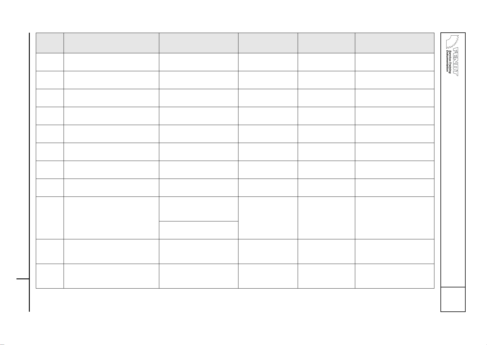
FENDT 400 Vario COM III, FENDT 700 Vario COM III, FENDT 800 Vario COM III Faults
B
OVERALL SYSTEM/TRACTOR
Fault code table COM III
Service Training
400 .. 1001- 724 .. 1001- 731 .. 1001-
401 .. 1001- 725 .. 1001-
402 .. 1001- 726 .. 1001-
403 .. 1001- 727 .. 1001-
404 .. 1001- 729 .. 1001-
0000 B T000434
Ver sio n 1
20/09/2007
33
8.3.11 A014 - ECU, EPC OBE E-box fault
(raise output)
Control barred and
locked
Wiring diagram
Sheet 25
REAR EPC
ACTUATION/STATUS
8.3.12 A014 - ECU, EPC OBE E-box fault
(lower output)
Control barred and
locked
Wiring diagram
Sheet 25
REAR EPC
ACTUATION/STATUS
8.3.14 S029 - Switch (external), raise rear
power lift, left
Signal line fault
Faulty button
Control barred and
locked
Wiring diagram
Sheet 25
REAR EPC
EXTERNAL BUTTONS
8.3.15 S030 - Switch (external), lower rear
power lift, left
Signal line fault
Faulty button
Control barred and
locked
Wiring diagram
Sheet 25
REAR EPC
EXTERNAL BUTTONS
8.3.16 A014 - ECU, EPC OBE Voltage < 1 V Control barred and
locked
Wiring diagram
Sheet 25
REAR EPC
CURRENT FAULT STATUS
8.3.17 A014 - ECU, EPC OBE Supply voltage >18 V Control barred and
locked
Wiring diagram
Sheet 25
8.3.18 S027 - Switch (external), raise rear
power lift, right
Signal line fault, button faulty Control barred and
locked
Wiring diagram
Sheet 25
REAR EPC
EXTERNAL BUTTONS
8.3.19 S028 - Switch (external), lower rear
power lift, right
Signal line fault, button faulty Control barred and
locked
Wiring diagram
Sheet 25
REAR EPC
EXTERNAL BUTTONS
8.3.22 B030 - Sensor, rear power lift posi-
tion
Signal fault Control barred and
locked
Wiring diagram
Sheet 25
REAR EPC
SPECIFIED VALUE/POSITION
SENSOR
Supply of 10.0 V from A014
faulty
8.3.23 A004 - ECU, control panel
Specified value setting for rear power lift "Depth control"
Signal line fault Control barred and
locked
REAR EPC
SPECIFIED VALUE/POSITION
SENSOR
8.3.26 External position sensor for rear
power lift
Signal line fault
Sensor out of position
Sensor faulty
Control barred and
locked
Wiring diagram
Sheet 25
Fault
code
DIN brief description Cause Consequences Reference FENDIAS / Note
Page 96

FENDT 400 Vario COM III, FENDT 700 Vario COM III, FENDT 800 Vario COM III Faults
B
OVERALL SYSTEM/TRACTOR
Fault code table COM III
400 .. 1001- 724 .. 1001- 731 .. 1001-
401 .. 1001- 725 .. 1001-
402 .. 1001- 726 .. 1001-
403 .. 1001- 727 .. 1001-
404 .. 1001- 729 .. 1001-
0000 B T000434
Ver sio n 1
20/09/2007
34
8.3.28 A004 - ECU, control panel Fault in rear EPC quick lift
switch
"Raise" and "Lower"
only possible via external buttons.
Wiring diagram
Sheet 25
REAR EPC
ACTUATION/STATUS
8.3.31 B031 - Sensor, right draught sensing pin
Signal line fault
Sensor faulty
Supply of 10.0 V from A014
faulty
Limited performance
during traction control
Wiring diagram
Sheet 25
REAR EPC
DRAUGHT SENSING PIN
8.3.32 B032 - Sensor, left draught sensing
pin
Signal line fault
Sensor faulty
Supply of 10.0 V from A014
faulty
Limited performance
during traction control
Wiring diagram
Sheet 25
REAR EPC
DRAUGHT SENSING PIN
8.3.33 A014 - ECU, EPC OBE
G001 - Battery 1 (12 VDC)
Battery voltage < 11.0 V Control barred and
locked
Wiring
diagram
Sheet 25
8.3.40 A004 - ECU, control panel
Rear power lift quick lift switch
Switch faulty Raising and lowering
only via external controls
Wiring diagram
Sheet 25
REAR EPC
ACTUATION/STATUS
CAN (K bus) fault A004/A014
8.3.41 A004 - ECU, control panel
Rear power lift quick entry button
Faulty button Quick entry not func-
tioning
Wiring diagram
Sheet 25
REAR EPC
ACTUATION/STATUS
CAN (K bus) fault A004/A014
8.3.42 A004 - ECU, control panel
Rear EPC, hitch function
Faulty button Hitch function not op-
erational
Wiring diagram
Sheet 25
REAR EPC
ACTUATION/STATUS
CAN (K bus) fault A004/A014
8.3.43 A004 - ECU, control panel
Automatic function (switching from
control panel to joystick)
Faulty button Switching not possi-
ble
Wiring diagram
Sheet 25
REAR EPC
ACTUATION/STATUS
CAN (K bus) fault A004/A014
Fault
code
DIN brief description Cause Consequences Reference FENDIAS / Note
Page 97

FENDT 400 Vario COM III, FENDT 700 Vario COM III, FENDT 800 Vario COM III Faults
B
OVERALL SYSTEM/TRACTOR
Fault code table COM III
Service Training
400 .. 1001- 724 .. 1001- 731 .. 1001-
401 .. 1001- 725 .. 1001-
402 .. 1001- 726 .. 1001-
403 .. 1001- 727 .. 1001-
404 .. 1001- 729 .. 1001-
0000 B T000434
Ver sio n 1
20/09/2007
35
8.3.50 B031 - Sensor, right draught sensing pin
Draught sensing pin is overloaded by stress on the lifting
gear in the upper range (90100% lift height) due to the
setting being too narrow.
Fault code will not be
stored
Wiring diagram
Sheet 25
REAR EPC
DRAUGHT SENSING PIN
8.3.51 B032 - Sensor, left draught sensing
pin
Draught sensing pin is overloaded by stress on the lifting
gear in the upper range (90100% lift height) due to the
setting being too narrow.
Fault code will not be
stored
Wiring diagram
Sheet 25
REAR EPC
DRAUGHT SENSING PIN
9.1.50 Y019 - Auxiliary control valve No signal from valve via bus
line.
No valve operation
available
Wiring diagram
Sheet 28
FRONT POWER LIFT/VENDI
9.1.51 Y019 - Auxiliary control valve EEPROM inconsistent Valve moves into neu-
tral position
FRONT POWER LIFT/VENDI
9.1.52 Y019 - Auxiliary control valve Supply voltage < 8 V Valve moves into neu-
tral position
FRONT POWER LIFT/VENDI
9.1.53 Y019 - Auxiliary control valve Supply voltage > 18 V Valve moves into neu-
tral position
FRONT POWER LIFT/VENDI
9.1.54 Y019 - Auxiliary control valve Main piston travel too short
due to drop of control pressure below 22 bar
Valve moves into neutral position
Check control pressure M5, check diaphragm
accumulator, check
RV7/FP
FRONT POWER LIFT/VENDI
Hydraulic oil temperature too
low
9.1.55 Y019 - Auxiliary control valve Overvoltage (> 45 V) Valve moves into neu-
tral position
9.1.56 Y019 - Auxiliary control valve Output fault at control valve
magnet
Valve moves into neutral position
FRONT POWER LIFT/VENDI
9.1.57 Y019 - Auxiliary control valve Internal position sensor fault Valve moves into neu-
tral position
FRONT POWER LIFT/VENDI
Fault
code
DIN brief description Cause Consequences Reference FENDIAS / Note
Page 98

FENDT 400 Vario COM III, FENDT 700 Vario COM III, FENDT 800 Vario COM III Faults
B
OVERALL SYSTEM/TRACTOR
Fault code table COM III
400 .. 1001- 724 .. 1001- 731 .. 1001-
401 .. 1001- 725 .. 1001-
402 .. 1001- 726 .. 1001-
403 .. 1001- 727 .. 1001-
404 .. 1001- 729 .. 1001-
0000 B T000434
Ver sio n 1
20/09/2007
36
9.1.58 Y019 - Auxiliary control valve Main piston cannot return to
neutral position due to oil contamination.
Manual actuation,
actuator must not
have any play, actuator must move to the
centre position by itself
FRONT POWER LIFT/VENDI
9.1.59 Y019 - Auxiliary control valve Main piston cannot return to
neutral position when
switched on due to oil contamination.
FRONT POWER LIFT/VENDI
9.1.5A Y019 - Auxiliary control valve Main piston deflected too far Valve moves into neu-
tral position
FRONT POWER LIFT/VENDI
9.1.5B Y019 - Auxiliary control valve Floating position is not
reached
Valve moves into neutral position
FRONT POWER LIFT/VENDI
9.1.5C Y019 - Auxiliary control valve Floating position has been de-
flected manually
No consequences FRONT POWER LIFT/VENDI
9.1.5F Y019 - Auxiliary control valve Specified value message
missing
Valve moves into neutral position
FRONT POWER LIFT/VENDI
Configuration message missing
Specified value message is
not plausible
Configuration message is not
plausible
Potentiometer or PWM fault
9.1.A0 A002 - ECU, enhanced control EEPROM fault while saving Set values (enhanced
controls) not stored.
9.1.A1 A002 - ECU, enhanced control EEPROM fault while loading Set values (enhanced
controls) cannot be
read.
Fault
code
DIN brief description Cause Consequences Reference FENDIAS / Note
Page 99

FENDT 400 Vario COM III, FENDT 700 Vario COM III, FENDT 800 Vario COM III Faults
B
OVERALL SYSTEM/TRACTOR
Fault code table COM III
Service Training
400 .. 1001- 724 .. 1001- 731 .. 1001-
401 .. 1001- 725 .. 1001-
402 .. 1001- 726 .. 1001-
403 .. 1001- 727 .. 1001-
404 .. 1001- 729 .. 1001-
0000 B T000434
Ver sio n 1
20/09/2007
37
9.1.B0 B040 - Sensor, front power lift posi-
tion
Not calibrated No position control
available
FRONT POWER LIFT
Calibration code "9002"
9.1.B1 B040 - Sensor, front power lift posi-
tion
Signal fault No position control
available
Wiring diagram
Sheet 27
FRONT POWER LIFT
8.5 V supply fault A013 fuse 11
9.1.B2 A004 - ECU, control panel
Depth control specified value potentiometer
Not calibrated Specified value can-
not be set
FRONT POWER LIFT
Calibration code "9001"
9.1.B3 A004 - ECU, control panel
Depth control specified value potentiometer
Signal fault, Specified value can-
not be set
FRONT POWER LIFT
9.1.C0 A004 - ECU, control panel
Control panel
Not available or bus not connected
9.1.C1 A004 - ECU, control panel
Automatic system (switching from
control panel/joystick)
Faulty button FRONT POWER LIFT
9.1.C2 A004 - ECU, control panel
Valve locking
Faulty button FRONT POWER LIFT
9.1.C3 A004 - ECU, control panel
Floating position
Faulty button FRONT POWER LIFT
9.1.C4 A004 - ECU, control panel
"Raise" quick lift switch
Faulty button FRONT POWER LIFT
9.1.C5 A004 - ECU, control panel
"Lower" quick lift switch
Faulty button FRONT POWER LIFT
9.1.C6
9.1.C7
9.1.C8
9.1.C9
9.1.CA
A004 - ECU, control panel CAN bus faulty Unspecified malfunc-
tions
Fault
code
DIN brief description Cause Consequences Reference FENDIAS / Note
Page 100

FENDT 400 Vario COM III, FENDT 700 Vario COM III, FENDT 800 Vario COM III Faults
B
OVERALL SYSTEM/TRACTOR
Fault code table COM III
400 .. 1001- 724 .. 1001- 731 .. 1001-
401 .. 1001- 725 .. 1001-
402 .. 1001- 726 .. 1001-
403 .. 1001- 727 .. 1001-
404 .. 1001- 729 .. 1001-
0000 B T000434
Ver sio n 1
20/09/2007
38
9.1.D0 S021 - Switch (external), raise front
power lift
Faulty button Function non-opera-
ble
Wiring diagram
Sheet 27
FRONT POWER LIFT
9.1.D1 S022 - Switch (external), lower
front power lift
Faulty button Function non-opera-
ble
Wiring diagram
Sheet 27
FRONT POWER LIFT
9.1.D2 S021 - Switch (external), raise front
power liftS022 - Switch (external),
lower front power lift
Double button operation (button possibly stuck)
Wiring diagram
Sheet 27
FRONT POWER LIFT
A.1.10 Y015 - Auxiliary control valve No signal from valve to valve
bus
No valve operation
available
Wiring diagram
Sheet 28
A.1.11 Y015 - Auxiliary control valve EEPROM inconsistent Valve moves into neu-
tral position
A.1.12 Y015 - Auxiliary control valve Valve moves into neu-
tral position
A.1.13 Y015 - Auxiliary control valve Supply voltage > 18 V Valve moves into neu-
tral position
A.1.14 Y015 - Auxiliary control valve Main piston travel too short
due to drop of control pressure below 22 bar
Valve moves into neutral position
Check control pressure M5, check diaphragm
accumulator, check
RV7/FP
ELECTRICAL VALVES VALVE
1/VENDI
Hydraulic oil temperature too
low
A.1.15 Y015 - Auxiliary control valve Overvoltage (> 45 V) Valve moves into neu-
tral position
A.1.16 Y015 - Auxiliary control valve Output fault at control valve
magnet
Valve moves into neutral position
ELECTRICAL VALVES VALVE
1/VENDI
A.1.17 Y015 - Auxiliary control valve Internal position sensor fault Valve moves into neu-
tral position
ELECTRICAL VALVES VALVE
1/VENDI
Fault
code
DIN brief description Cause Consequences Reference FENDIAS / Note
 Loading...