

Page 1

XP SERIES
LOUDSPEAKER SYSTEMS
From Fender Pro Audio
Owner's Manual for
XP 110 / 112 / 115
P/N 052004
Page 2

Fender Musical Instruments
7975 North Hayden Road, Scottsdale, Arizona 85258 U.S.A.
Fender knows the importance of sound reinforcement. From the simple box-top mixer
to today's professional touring concert systems, the need to communicate, to make the
connection between the performer and the audience is foremost in Fender's mind.
Perhaps no other single piece of gear can make or break your band's sound. You see,
your sound system is more than just a combination of dials, wires and speakers. It is
an integral part of the audio chain and should be treated with special care and attention
to detail.
At Fender, we know what building quality musical instruments and sound reinforcement
equipment is all about. In fact, many of the world's best sounding electric musical
instruments and sound reinforcement equipment proudly wear the Fender name.
Whether you need a simple box top powered mixer for your Saturday afternoon jam, or
a professional full-size concert system, Fender has the sound reinforcement equipment
to meet your needs. Likewise, your decision to purchase Fender pro audio gear is one
you will appreciate with each performance for years to come.
Wishing you years of enjoyment and a heartfelt thank you,
Bill Schultz
Bill Schultz
Chairman
Fender Musical Instruments Corporation
Page 3

INTRODUCTION
XP SERIES 110 / 112 / 115
XP SERIES 110 / 112 / 115
PROFESSIONAL LOUDSPEAKER
PROFESSIONAL LOUDSPEAKER
SYSTEMS
SYSTEMS
3/4” Birch Plywood Cabinet
High Current 1/4” Phone Jacks
Dual Piezoelectric Horn
Rugged Metal Grille
Metal Corners and Rubber Feet
Tough Synthetic Indoor/Outdoor
Carpet
Thank you for purchasing an XP Series 110 / 112 /
115 Loudspeaker System from Fender®Pro Audio. We
are sure you will find it both a unique and effective
sound reinforcement product, providing years of
trouble-free service day in and day out.
XP Series Loudspeaker Systems are professional, fullrange, two-way, compact loudspeakers designed for
the most demanding permanent or portable sound
reinforcement requirements. With scientifically derived
trapezoidal shapes, these speakers are ideal for use
as a two-way system or as the mid / high pack in a
three-way set-up incorporating a Fender 115sA /
118sA subwoofer loudspeaker system.
XP Series Loudspeaker Systems are designed to form
the basis of everything from a small public address
system to the nightly rigors of a “working band’s” sound
system. After moisture sealing, XP Series cabinets are
covered in a rugged black carpet. Likewise, XP Series
cabinets also feature metal corners and rubber feet for
a longer life and lasting looks.
Please read through this owner’s guide in order to more
fully understand the operational characteristics of your
XP Series Loudspeaker enclosure.
CAUTION: Almost all speakers produce strong
magnetic fields which may interfere with the
normal operation of nearby electronic devices,
including televisions and computer video monitors.
To reduce or eliminate interference, increase the
distance between this product and other nearby
electronic devices.
3
Page 4

SPEAKER WIRING AND CONNECTIONS
Parallel or series are the two basic ways which multiple
speakers can be connected to a single power amplifier.
When speakers are connected in parallel, their
combined impedance decreases. For speakers wired
in series the opposite is true, their combined
impedance increases. Thus, when speakers are wired
in series, higher impedance speakers in the series draw
more power from the amplifier than do speakers in the
series with lower impedances. When speakers are
wired in parallel, the opposite is true. Higher
impedance speakers will draw less power from the
amplifier than lower impedance speakers will draw.
At Fender®, we recommend connecting multiple
speakers in parallel for several reasons. First, if one
speaker fails, the others will continue to operate. Second,
because in a series connection one speaker affects the
output of the other speakers, unpredictable frequency
response is a concern. Third, most speaker cabinets
are already wired for parallel connections making parallel
connections the most common wiring method.
Below are two charts demonstrating how to calculate
both parallel and series impedance.
Keep in mind, power and audio signal cables are the
most common sources of sound system failure. Well
made and carefully maintained cables are essential to
the reliability of the entire sound system. If long speaker
cables are required, it is important to ensure the cable‘s
gauge is sufficient to transfer all of the available
amplifier power to the speakers rather than absorbing
the power itself. As a rule of thumb, larger wires are
better as they conduct more power to the speakers
(larger wire has smaller gauge numbers).
Below are two charts listing speaker wire gauges and
recommendations for best results.
SPEAKER WIRE GAUGE
100'-UP
(30.5 m-UP)
50'-100'
(15.25-30.5 m)
*25'-50'
(7.60-15.25 m)
10
12
14
12
14
16
14
*16 18
PARALLEL IMPEDANCE
Z
5.3* 8
16Ω*
4 5.3
8Ω
Cabinet B
Impedance
8Ω*16Ω
Cabinet A
Impedance
*Example- Cabinet A is 8 ohms. Cabinet B is
16 ohms . The total impedance when connected
in parallel is:
Z
=
p
181
SERIES IMPEDANCE
18 20* 24 32
16Ω*
8Ω
10 12 16 24
4Ω
Cabinet B
6 8 12 20
Impedance
2Ω
4 6 10 18
2Ω 4Ω*8Ω16Ω
Cabinet A
Impedance
+ -
1
+
16
Z
=
p
1
+
Z
+
-
= 5.3 ohms.
=
+
s
+ -
1
1
1
...
Z
Z
2n1
+
AB
-
ZZZ
...
2n1
+
A
-
+
B
-
10'-25'
(3.05-7.60 m)
0'-10'
SPEAKER WIRE LENGTH
(0.00-3.05 m)
16
18
4Ω
18
18
*8Ω
18
18
16Ω
SPEAKER IMPEDANCE [z]
*Example - If the speaker wire length
required is between 25-50 feet (7.60-
15.25 meters) and the speaker
impedance is 8Ω, the minimum
recommended speaker wire gauge is 16.
AWG
18
16
14
12
10
8
Cross-
Section
[mm ]
0.83
1.32
2.10
3.32
5.27
8.38
Resistance in Ω per foot
2
(30.5 cm) @ 77º F (25º C)
.00651
.00409
.00258
.00162
.00102
.00064
4
Page 5

XP SERIES SPEAKER CONNECTIONS
30º
The XP Series Loudspeaker Systems’ 1/4" jacks are
wired in parallel allowing any one of the connectors to
be used as an input and any other as an output. This
allows "daisy chaining" of multiple loudspeakers,
eliminating the need for several long, cumbersome runs
of speaker cable (see diagram on page 6). Their
connections are as follows:
Polarity Phone Jack
Positive (+) Tip
Negative (-) Sleeve
If XP enclosures are used as the mid / high pack in a
larger three-way loudspeaker array, an external
crossover may be used with the speaker and two
channels of power amplification will be required: one for
the low frequencies and another for the high frequencies
(see diagram on page 7).
SETUP SUGGESTIONS
The placement of any speaker can dramatically affect
its sound. Thus, there are several considerations to
review when placing loudspeakers.
First, the range of the horizontal coverage should be
determined. The speaker may be used as a single unit,
as part of a pair, or as part of a group of widely spaced
enclosures, in any case, maximum horizontal coverage
will be desired. Examples of these types of setups
are shown. The horn in this configuration has a
horizontal coverage angle of 70º and a vertical
coverage of 35º.
XP
Cabinet
Two speakers in a "loose pack" array
requiring maximum horizontal
coverage
NOTE: When setting up your XP Series enclosures, be
sure to place the cabinets in such a way as to minimize
overlapping radiating patterns.
A second consideration is for feedback and bass
performance. If the speaker is placed near a large, flat
wall, the bass output will increase by approximately 6
dB. Placing the speaker near a wall can cause
feedback. If this occurs, the speaker must be moved.
A third consideration is to what degree the speaker
should be "heard and not seen", especially in
permanent installations. Remember, where the
speaker cabinets are placed will effect both their tone
and radiating patterns.
XP
Cabinet
CARPET COVERING CARE
XP Series cabinets are covered in a
tough, soil resistant synthetic
indoor/outdoor carpet for long life and
lasting good looks. To clean the
carpeted cabinet, use a brush to wipe
away any smudges or dirt. For stubborn
stains, a sponge with a light soapy
solution may be used. Avoid spilling liquids on the
input panel, grille and speakers.
XP
Cabinet
Two speakers arranged as a mono or stereo
pair requiring maximum horizontal coverage
Stage
Audience
XP
Cabinet
5
Page 6
“DAISY CHAINING” XP SERIES ENCLOSURES
6
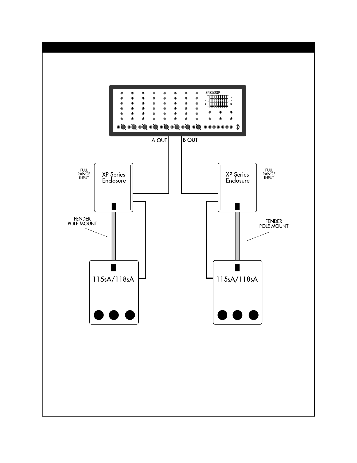
Page 7

USING AN ELECTRONIC CROSSOVER WITH XP SERIES ENCLOSURES
XP Series
Enclosure
INPUT
-
∞
- ∞-
∞
PCN-2 ELECTRONIC CROSSOVER
∞
HIGH
OUT
INPUT
- ∞- ∞-
LOW
OUT
XP Series
Enclosure
7
Page 8

SPECIFICATIONS
MODEL 110-XP 112-XP 115-XP
PART NUMBER 071-1100-100 071-1200-100 071-1500-100
MAXIMUM dB SPL
OUTPUT LONG TERM 120 dB 121 dB 121 dB
CABINET 3/4" (1.9 cm) 3/4" (1.9 cm) 3/4" (1.9 cm)
Birch Plywood Birch Plywood Birch Plywood
CONNECTIONS (2) 1/4" Phone Jacks (2) 1/4" Phone Jacks (2) 1/4" Phone Jacks
DRIVER Low: 10" (25.4 cm) woofer 12" (30.5 cm) woofer 15" (38.1 cm) woofer
2" (5 cm) voice coil 2" (5 cm) voice coil 2.5" (6.35 cm) voice coil
High: 1" (2.5 cm) Exit Throat 1" (2.5 cm) Exit Throat 1" (2.5 cm) Exit Throat
Polymer Diaphragm Polymer Diaphragm Polymer Diaphragm
Dual Piezoelectric Driver Dual Piezoelectric Driver Dual Piezoelectric Driver
FREQUENCY Axial
RESPONSE +/- 3 dB: 65 Hz to 20kHz 60 Hz to 20kHz 60 Hz to 20kHz
AXIAL SPL @
SENSITIVITY 1W/1m: 94 dB 95 dB 95 dB
POWER RATING 100W 100W 150W
NOMINAL IMPEDANCE 8Ω 8Ω 8Ω
DIMENSIONS Height 20.25" (51 cm) 21.25" (54 cm) 23.8" (60 cm)
Width (front) 14.6" (37 cm) 18" (46 cm) 20.9" (53 cm)
Width (rear) 6.4" (16 cm) 6.4" (16 cm) 8.4" (21 cm)
Depth 15.6" (40 cm) 18.4" (47 cm) 19.6" (50 cm)
WEIGHT 37 lbs. (16.7 kg) 50 lbs. (22.7 kg) 58 lbs. (26.3 kg)
A PRODUCT OF:
FENDER MUSICAL INSTRUMENTS CORP.
CORONA, CA 91720 USA
 Loading...