

Page 1

POWERED MIXERS
From Fender Pro Audio
6302 / 8302
6302 / 8302
Owner's Manual for
SRM 6302 / 8302
P/N 050804
REV A
Page 2

Fender Musical Instruments
7975 North Hayden Road, Scottsdale, Arizona 85258 U.S.A.
Fender knows the importance of sound reinforcement. From the simple box-top mixer
to today's professional touring concert systems, the need to communicate, to make the
connection between the performer and the audience is foremost in Fender's mind.
Perhaps no other single piece of gear can make or break your band's sound. You see,
your sound system is more than just a combination of dials, wires and speakers. It is
an integral part of the audio chain and should be treated with special care and attention
to detail.
At Fender, we know what building quality musical instruments and sound reinforcement
equipment is all about. In fact, many of the world's best sounding electric musical
instruments and sound reinforcement equipment proudly wear the Fender name.
Whether you need a simple box top powered mixer for your Saturday afternoon jam, or
a professional full-size concert system, Fender has the sound reinforcement equipment
to meet your needs. Likewise, your decision to purchase Fender pro audio gear is one
you will appreciate with each performance for years to come.
Wishing you years of enjoyment and a heartfelt thank you,
Bill Schultz
Bill Schultz
Chairman
Fender Musical Instruments Corporation
Page 3

INTRODUCTION
SRM 6302
SRM 6302
PROFESSIONAL POWERED
PROFESSIONAL POWERED
MIXER
MIXER
/ 8302
/ 8302
150 Watts per Channel at 4Ω
Assignable Dual Power Amplifiers
9-Band Assignable Graphic Equalizer
with 30mm Sliders
3-Band Equalizer per Input Channel
+48V DC Phantom Power
Individual Channel Effects Level Control
Both 1/4 inch Phone TRS and 3-Pin XLR
Female Input Connectors
Patch Points for Line Level Output and
Power Amp Inputs and Outboard Gear
Full-bodied Spring Reverb
The SRM 6302 / 8302: a dual 150 watt professional
powered mixer from your friends at Fender®Pro
Audio. We are sure you will find your new SRM
6302 / 8302 to be both a unique and effective
sound reinforcement product, providing years of
trouble-free service.
With ease of setup in mind, the integrated
mixer/amplifier design of your SRM 6302 / 8302
makes it a complex and versatile unit, yet simple to
operate. Enclosed in a boxtop style cabinet, your
SRM 6302 / 8302 features individual channel
preamps, an assignable dual power amplifier, +48V
DC phantom power, a 9-band graphic equalizer, line
and mic level channel inputs, a patch bay and much,
much more. With 1/4 inch TRS phone jacks, 3-Pin
XLR female input jacks and stereo RCA input jacks,
your SRM 6302 / 8302 can accommodate almost
any input connection and signal level.
Ideal for live music, churches, auditoriums, hotel
conference or meeting rooms, your SRM 6302 /
8302 is suitable for a wide variety of sound
reinforcement applications. With its assignable dual
power amplifier, your SRM 6302 / 8302 can feed
your main front of house speakers while
simultaneously providing power for stage monitors.
Its front panel patch bay makes using outboard
effects gear and signal processing equipment a
snap. Moreover, the patch bay provides easy
access for adding or rerouting power amplifiers.
Designed to meet the most demanding needs of
audio professionals, your SRM 6302 / 8302 will
provide years of reliable, trouble-free service, day in
and day out. Please read through this owner’s
manual in order to more thoroughly understand the
operation of your SRM 6302 / 8302.
WARNING:
- TO REDUCE THE RISK OF FIRE OR SHOCK
HAZARD, DO NOT EXPOSE THIS UNIT TO RAIN OR
MOISTURE.
- NO USER SERVICEABLE PARTS INSIDE, REFER
SERVICING TO QUALIFIED PERSONNEL ONLY.
- ALLOW AT LEAST 3” (7.6 cm) AROUND THE UNIT
FOR PROPER VENTILATION.
- THIS UNIT MUST BE EARTH GROUNDED.
3
Page 4

INPUT CHANNEL CONTROL FUNCTIONS
PA TCH BAY PANEL CONNECTIONS
A. EFFECTS - This knob controls
the amount of signal its respective
A
channel sends to the overall effects
mix. When the knob is set at 0, the
0
EFFECTS
MAX
output is “dry”.
B. HIGH - Adjusts the amount of
high frequency boost or cut in the
B
channel. When all the tone controls
are set at 0 (straight up), the
+15 15
HIGH
HIGH
channel is “flat” with no frequencies
cut or boosted.
C. MID - Adjusts the amount of
C
middle frequency boost or cut in
the channel.
+15 15
MID
MID
D. LOW - Adjusts the amount of
low frequency boost or cut in the
channel.
D
E. MONITOR - This knob controls
+15 15
LOW
LOW
the amount of signal its respective
channel sends to the monitor mix.
When the knob is set at 0, the
E
channel’s signal is not sent to the
monitor bus.
0
MONITOR
MAX
F. LEVEL - Adjusts the volume
control of the individual channel.
Rotating the knob clockwise
F
increases the respective channel’s
contribution to the “Main Out” mix.
Adjust this control after the MAIN or
LEVEL
MAX
overall volume of the SRM 6302 /
0
8302 has been set.
INPUT CHANNEL CONNECTIONS
G. LINE - Plug your instrument in
G
here. This 1/4 inch TRS balanced
input jack suited for use with items
having a line level output such as
LINE
MIC
impedance microphones. Pins 2 and 3 provide
Phantom Power (+48V DC) for condenser style
microphones when the phantom power switch is on.
high impedance microphones,
keyboards, drum machines,
outboard effects, etc. It accepts
H
both balanced and unbalanced
cables
H. MIC - Plug your microphone in
here. This three pin XLR balanced
female input connector is intended
for input signals from low
KMI
MAIN OUT
J
PA 1 IN
I. MAIN OUT - This 1/4 inch, TS, unbalanced, line
level output is designed to feed the SRM 6302 /
8302’s main bus signal to an external power
amplifier or main house mixer.
J. PA 1 IN - This 1/4 inch, TS, unbalanced, line
level input jack allows the SRM 6302 / 8302’s power
amplifier #1 (PA 1) to be fed from an external signal
source. When this connection is used, the “main
out” connection to PA 1 is overridden.
K. MON OUT - This 1/4 inch, TS, unbalanced, line
level output is designed to feed the SRM 6302 /
8302’s monitor bus signal to an external power
amplifier or monitor system.
L. PA 2 IN - This 1/4 inch, TS, unbalanced, line
level input jack allows the SRM 6302 / 8302’s power
amplifier #2 (PA 2) to be fed from an external signal
source. When this connection is used, the internal
connection to PA 2 is overridden.
M. EFFECTS OUT/FOOTSWITCH - This 1/4 inch,
TS, unbalanced, line level output jack is designed to
feed the SRM’s effects bus signal to an external
signal processing device, such as a digital delay or a
chorus unit. When a footswitch (P/N 048458,
optional) is inserted into this jack, the SRM’s internal
reverb can be turned on or off remotely.
N. EFFECTS IN - This 1/4 inch, unbalanced, TS, line
level input jack is designed to accept signal from an
external processing device, such as a digital delay or
a chorus unit. The signal entering this jack is mixed
into the Main and Monitor using the “Tape/Effects”
controls labeled “Return to Main” and “Return to
Monitor”.
MON OUT EFFECTS OUT/
PA 2 IN EFFECTS IN
FOOTSWITCH
L
N
4
Page 5
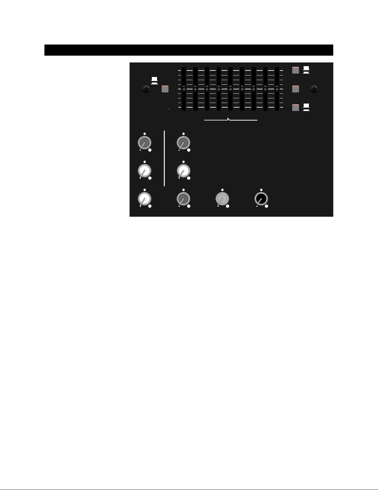
MASTER CONTROL PANEL FUNCTIONS
A. EQ ASSIGN - This button
switches the graphic equalizer
between the main and the
monitor bus. When this
button is pressed, the EQ is
assigned to the monitor bus.
B. GRAPHIC EQUALIZER -
EQ ASSIGN
A
MAIN
MON
+12dB
OdB
12dB
This 9 band graphic equalizer
consists of active band pass
/ band reject filters spaced at
octave intervals. Moving the
sliders up or down boosts or
cuts the gain at the indicated
frequency.
TAPE/
EFFECTS
F
MAX
0
RETURN
TO MONITOR
GJ
REVERB
0
RETURN
TO MONITOR
C. PHANTOM POWER When this button is pressed,
a +48V DC Phantom Power
supply is activated, necessary
0
RETURN
TO MAIN
H
0
RETURN
TO MAIN
MAX
for some condenser style
microphones. Before
plugging or unplugging any
0
MAIN
MAX
0
MONITOR
microphone, make sure the
Phantom Power supply is off.
D. POWER LED - This LED illuminates when the
SRM 6302 / 8302 is on.
E. PA 2 ASSIGN - This button switches the second
power amplifier between the main and the monitor bus.
When this button is pressed, the second power
amplifier is assigned to the monitor bus providing
power to drive monitor speakers. When this button is
in the Main position, the second power amplifier is
assigned to the main bus providing additional power for
front of house enclosures. When connecting the
speakers to your SRM 6302 / 8302, connect one
cabinet to the PA 1 Out jack and the other to the PA2
Out jack.
F. TAPE/EFFECTS RETURN TO MONITOR Adjusts the tape/effects signal level sent to the
monitor mix from either the Effects In or Tape In jacks.
Rotating the knob clockwise increases the tape/effects
signal sent to the monitor mix.
G. TAPE/EFFECTS RETURN TO MAIN - Adjusts
the tape/effects signal level sent to the main mix from
either the Effects In or Tape In jacks. Rotating the
knob clockwise increases the tape/effects signal sent
to the main mix.
H. MAIN - The main output volume control of the
SRM 6302 / 8302. Any adjustments to this control
will affect the signal level at the Main Out, as well as,
PA1 and PA2 depending upon the PA2 Assign
switch position and patch bay configuration.
+12dB
PHANTOM POWER
OdB
D
POWER
63 125 250 500 1k 2k 4k 8k 16k
GRAPHIC EQUALIZER
B
12dB
PA 2 ASSIGN
I
MAX
MAX
KLM
MAX
I. REVERB RETURN TO MONITOR - Adjusts the
amount of reverb signal level sent to the monitor mix.
Rotating the knob clockwise increases the reverb
signal sent to the monitor mix. When the knob is set
at 0, the output is “dry”.
J. REVERB RETURN TO MAIN - Adjusts the
amount of reverb signal level sent to the main mix.
Rotating the knob clockwise increases the reverb
signal sent to the main mix. When the knob is set at
0, the output is “dry”.
K. MONITOR - The monitor output volume control
of the SRM 6302 / 8302. Any adjustments to this
control will affect the signal level at the Mon Out, as
well as, PA1 and PA2 depending upon the PA2
Assign switch position and patch bay configuration.
L. EFFECTS - Adjusts the signal level present at the
Effects Out / Footswitch jack, as well as, the signal
driving the reverb. Rotating the knob clockwise
increases the amount of tape/effects and reverb drive
signal. When the knob is set at 0, there is no effects
drive signal.
M. REC OUT - Adjusts the tape out signal level of
the SRM 6302 / 8302. (The Main Out signal feeds
this control.) Rotating the knob clockwise increases
the output level. When the knob is set at 0, there is
no signal level output.
5
0
EFFECTS
MAX
0
REC OUT
MAX
OFF
C
ON
MAIN
E
MON
Page 6

TAPE INPUT / OUTPUT JACKS
O. TAPE IN - Unbalanced
phono (RCA) input jacks
L
designed for use with a tape
player, CD player, etc. These
jacks sum the stereo left and
right input signal to a mono
R
signal useful for playing
TAPE
OUT
prerecorded music. The
P
tape/effects return to main and
O
IN
tape/effects return to monitor control the volume to
these buses respectively.
REAR PANEL
Q
PARALLEL SPK JACKS
Q. PA 1 OUT / PA 2 OUT - These are speaker level
output jacks designed to feed your main or monitor
speaker enclosures. Remember, the minimum
impedance load is 4 ohms. Connecting a load of
less than 4 ohms may result in unsatisfactory
performance such as overheating to the point of
thermal shutdown. PA 1 Out jacks are intended for
the main speakers. The use of the PA 2 Out jacks
depends on the position of the PA 2 Assign switch.
(See item E on page 5).
R
150W
4Ω MIN TOTAL
POWER
ON
PA 2
OUT
R.POWER SWITCH -
Turns the AC power ON
and OFF. When the switch
is in the OFF position, the
SRM 6302 / 8302 is
completely shut down.
P. TAPE OUT - Unbalanced phono (RCA) output
jacks designed for use with a tape recorder. They
produce a mono signal. The rec out knob controls
the tape out signal level.
PA 1
OUT
PARALLEL SPK JACKS
150W
4Ω MIN TOTAL
S. SUPPLY CORD - This
S
is a grounding type supply
cord to reduce the
possibility of shock
hazard. Completely
unwind the cord from its
cord wrap to prevent
blocking air flow to the
transformer. Be sure to
connect the cord to a
grounded receptacle. DO
NOT ALTER THE AC
PLUG.
OFF
6
Page 7

SPEAKER WIRING AND CONNECTIONS
Parallel or series are the two basic ways which
multiple speakers can be connected to a single
power amplifier. When speakers are connected in
parallel, their combined impedance decreases. For
speakers wired in series the opposite is true, their
combined impedance increases. Also, when
speakers are wired in series, higher impedance
speakers in the series draw more power from the
amplifier than do speakers in the series with lower
impedances. When speakers are wired in parallel,
the opposite is true.
At Fender®, we recommend connecting multiple
speakers in parallel for several reasons. First, if one
speaker fails, the others will continue to operate.
Second, because in a series connection one
speaker affects the output of the other speakers,
unpredictable frequency response is a concern.
Third, most speaker cabinets are already wired for
parallel connections making parallel connections the
most common wiring method.
When using your SRM 6302 / 8302, be sure that the
minimum load connected to each channel is 4
ohms. Below are two charts demonstrating how to
calculate both parallel and series impedance.
Additionally, power and audio signal cables are the
most common sources of sound system failure.
Well made and carefully maintained cables are
essential to the reliability of the entire sound system.
If long speaker cables are required, it is important to
ensure the cable is sufficient to transfer all of the
available amplifier power to the speakers rather than
absorbing the power itself. As a rule of thumb,
larger wires are better as they conduct more power
to the speakers (larger wire has smaller gauge
numbers).
Below are two charts listing speaker wire gauges
and recommendations for best results.
SPEAKER WIRE GAUGE
100'-UP
(30.5 m-UP)
50'-100'
(15.25-30.5 m)
*25'-50'
(7.60-15.25 m)
10
12
14
12
14
16
14
*16 18
PARALLEL IMPEDANCE
Z
5.3* 8
16Ω*
4 5.3
8Ω
Cabinet B
Impedance
SERIES IMPEDANCE
16Ω*
Cabinet B
Impedance
8Ω*16Ω
Cabinet A
Impedance
*Example- Cabinet A is 8 ohms. Cabinet B is
16 ohms . The total impedance when connected
in parallel is:
18 20* 24 32
8Ω
10 12 16 24
4Ω
6 8 12 20
2Ω
4 6 10 18
2Ω 4Ω*8Ω16Ω
*Example- Cabinet A is 4 ohms. Cabinet B is
16 ohms. The total impedance when
connected in series is 4 + 16 = 20 ohms.
Z
p
Cabinet A
Impedance
=
1
181
+
+ -
16
Z
=
p
1
Z
+
-
= 5.3 ohms.
=
s
+ -
1
1
1
+
...
Z
Z
2n1
+
AB
-
ZZZ
...
+
2n1
+
A
-
+
B
-
10'-25'
(3.05-7.60 m)
0'-10'
SPEAKER WIRE LENGTH
(0.00-3.05 m)
16
18
4Ω
18
18
*8Ω
18
18
16Ω
SPEAKER IMPEDANCE [z]
*Example - If the speaker wire length
required is between 25-50 feet (7.60-
15.25 meters) and the speaker
impedance is 8Ω, the minimum
recommended speaker wire gauge is 16.
AWG
18
16
14
12
10
8
Cross-
Section
[mm ]
0.83
1.32
2.10
3.32
5.27
8.38
Resistance in Ω per foot
2
(30.5 cm) @ 77º F (25º C)
.00651
.00409
.00258
.00162
.00102
.00064
7
Page 8

INPUT / OUTPUT CONNECTIONS
BASIC SETUP OF YOUR SRM 6302 / 8302
Jack
MIC
INPUTS
LINE
INPUTS
MAIN,
MONITOR,
EFFECTS
OUTPUTS
FOOT
SWITCH
PA 1,
PA 2,
EFFECTS
INPUTS
TAPE
IN / OUT
PA 1,
PA 2
OUT
The SRM 6302 / 8302 has a variety of
connectors on its input / output panels.
Below is a chart listing the various types
and their pin outs.
Style Connection Pin Out
XLR
Female
1/4"
TRS
1/4" TS Unbalanced
1/4" TS
1/4" TS
Dual
RCA
1/4" TS Speaker
Balanced
Input
Balanced
Input
Output
Switch
Unbalanced
Input
Unbalanced
Input /
Output
Output
Pin 1 = GND
Pin 2 = POS
Pin 3 = NEG
Tip = POS Signal
Ring = NEG Signal
Sleeve = GND
Tip = Signal Output
Sleeve = GND
Tip = Signal
Sleeve = GND
Tip = Input Signal
Sleeve = GND
Inner Ring = Signal
Outer Shell = GND
Tip = Signal
Sleeve = GND
Before using the SRM 6302 / 8302,
please read and follow the steps listed
below:
1. IMPORTANT Heed all safety warnings when
operating the SRM 6302 / 8302.
2. Make sure the power switch is in the OFF position
and all volume levels are in the 0 position.
3. Next, plug the supply cord into a power source
with the correct voltage.
5. Connect the speaker cables from the SRM 6302 /
8302 PA out jacks to the input jacks of the speaker
cabinets.
6. Connect the cord(s) from any outboard gear,
microphones or other signal source(s) to the
appropriate input jack(s) on your SRM 6302 /
8302's.
7. First, turn all outboard gear, instruments and other
equipment ON, then the SRM 6302 / 8302.
8. Increase volume controls and effects level controls
to their desired levels, listening for feedback or
ringing.
9. When shutting down the SRM 6302 / 8302, turn
OFF the SRM 6302 / 8302 first then any additional
outboard gear, instruments or other equipment.
For more detail on setting up your SRM 6302 / 8302,
please refer to the diagrams on pages 10 thru 13.
8
Page 9

TROUBLESHOOTINGGROUNDING AND HUMS
Ground loops are one of the most
common causes of hum and buzz in
sound reinforcement systems and other
audio products. A ground loop usually
occurs if the separate pieces of
equipment are plugged into different AC
circuits. Also, if the audio wiring is placed too close
to the power cords, hums or buzzes can bleed into
the system. Still, improperly maintained power and
audio cables are yet another cause of bothersome
noise. In order to help minimize stray hums and
buzzes, here are some helpful hints.
1. Keep all electronics connected to the sound
system on the same electrical circuit.
2. Keep audio signal cables away from the AC
power cords.
3. Use balanced cables when applicable.
4. Always plug the SRM 6302 / 8302 into a
grounded AC electrical outlet.
5. Be sure to use properly maintained cords and
cables with the SRM 6302 / 8302.
TOLEX COVERING CARE
If the SRM 6302 / 8302 is set up but
does not function, please check the
following items:
• Is the SRM 6302 / 8302's power cord properly
plugged into an electrical outlet?
• Is there power at the outlet?
• (If applicable) does your instrument have power?
• Are the volume control knobs on the SRM 6302 /
8302 turned above the 0 position?
• Are the volume control knobs on your instruments
turned above their minimum position?
• Is the mic/instrument properly plugged into the
SRM 6302 / 8302?
• Is the mic/instrument turned on?
• Are your audio cables frayed, cut or damaged?
• If using a condenser mic, is the phantom power
turned on?
• If using an outboard gear, are the cords
properly connected?
• Is there power to the outboard gear?
• Are the levels on your outboard gear above their
minimum positions?
The SRM 6302 / 8302 is covered in
genuine Tolex®for long life and lasting
good looks. To clean the cabinet, use a
sponge with a light soapy solution.
Avoid spilling any liquids on the operating
surface, heat sink, grille, volume and tone controls,
switches and line cord. ALWAYS unplug the SRM
6302 / 8302 before cleaning it or approaching it with
fluids. Before plugging in the SRM 6302 / 8302 wait
until the unit has completely dried.
If after checking all of the above the SRM 6302 /
8302 is still not performing correctly, consult your
authorized Fender Service Center.
9
Page 10

SIMPLE SRM SETUP WITH MONITORS
1. Connect a microphone to a Mic input jack and any
keyboard or other instrument to a Line input jack.
2. Next, connect speaker cords from the PA 1 Out
jacks to the main speakers and from the PA 2 Out
jacks to the monitor speakers.
3. The level control in each channel strip adjusts the
amount of signal sent to the main bus where all
channel signals are summed. The Main control in
the master section adjusts the volume level to the
main speakers. The Monitor control in each
channel strip adjusts the amount of signal sent to
the monitor bus where all monitor channel signals
are summed. The Monitor control in the master
section adjusts the volume level to the monitor
speakers.
4. Be sure to turn the tape deck, keyboard or other
instruments and gear on first, then the SRM 6302 /
8302.
10
Page 11

RUNNING AN EFFECTS PROCESSOR THRU YOUR SRM 6302 / 8302
1. Connect speakers, microphones and other
equipment to the SRM 6302 / 8302 as before.
2. Next, connect a cord from the Effects
Out/Footswitch jack to the input of the effects
processing unit. Return the signal to the SRM 6302 /
8302 by connecting a cord from the output of the
effects unit to the Effects In jack on the SRM. (When
PA 2 is assigned to the main front of house
enclosures, be sure one enclosure is connected to a
PA 1 Out jack and the other is connected to a PA 2
Out jack.)
3. The Effects control in each channel strip adjusts
the amount of signal sent to the reverb / effects bus
where all the effects signals from the channels are
summed. The Effects control in the master section
adjusts the signal level to the effects processing unit
and the reverb pan.
4. Be sure to turn on the tape deck, keyboard or
other instruments and outboard gear before
powering up the SRM 6302 / 8302.
11
Page 12

SRM WITH AN EXTERNAL MONITOR POWER AMP FOR MONITOR SPEAKERS
1. Connect a cord from the Mon Out jack to the
monitor power amp and system. With an external
monitor power amp, the SRM’s second power
amp may be assigned to the main bus for
additional power to the front of house speakers.
When PA 2 is assigned to the main front of house
enclosures, be sure one enclosure is connected to
the PA 1 Out jacks and the other is connected to
the PA 2 Out jacks.
2. The Monitor control in the master section adjusts
the signal level to the monitor power amp.
3. Be sure to turn the tape deck, keyboard or other
instruments and gear on first, then the SRM 6302 /
8302.
12
Page 13

SRM WITH AN EXTERNAL POWER AMP FOR FRONT OF HOUSE SPEAKERS
1. Connect a cord from the Main Out jack to an
external power amp. Be sure one monitor enclosure
is connected to a PA 1 Out jack and the other is
connected to a PA 2 Out jack. (PA 1 power amp can
now be assigned to monitor speakers by connecting
a small, shielded jumper cable from the Mon Out jack
to PA 1 In. Next, connect the PA2 power amp to
Monitor Out by placing the PA2 Assign switch to the
Mon position. The Monitor control will now adjust
volume for both PA 1 and PA 2.)
2. The Main control in the master section adjusts
the signal level to your external power amp.
3. Be sure to turn your tape deck, keyboard or
other instruments and gear on first, then your SRM
6302 / 8302 and external power amplifier.
13
Page 14

SRM 6302 / 8302 SIGNAL FLOW DIAGRAM
Typical signal path
for each channel
LEVEL
MIC
INPUTS
LINE
21
3
CHANNEL EQ
HIGH
MID
LOW
TO PHANTOM BUS
EFFECTS
TO MONITOR BUS
TO MAIN BUS
TO EFFECTS/
REVERB BUS
EFFECTS IN
TAPE IN
MONITOR
PHANTOM
EFFECTS/REVERB
TAPE / EFFECTS
L
R
MAIN
MONITOR
MAIN
MONITOR
GRAPHIC EQ
EQ ASSIGN
RETURN TO MAIN
RETURN TO MONITOR
REC
OUT
PA 1
PA 2
ASSIGN
PA 2
EFFECTS/REVERB
MONITOR
PHANTOM
MAIN
L
TAPE
OUT
R
MAIN
OUT
PA 1
IN
PA 1 OUT
PA 1 OUT
MON OUT
PA 2 OUT
EFFECTS
PHANTOM
POWER
SWITCH
+48 VDC
REVERB RETURN
TO MONITOR
REVERB
DELAY LINE
REVERB RETURN
TO MAIN
14
PA 2 OUT
PA 2 IN
EFFECTS OUT/
FOOTSWITCH
Page 15

SPECIFICATIONS FOR THE SRM 6302
DESIGNATION TYPE PR 332
PART NUMBER 071-6321-000 (120 V)
071-6321-030 (240 V) Aust
071-6321-040 (230 V) UK
071-6321-060 (230 V) Euro
POWER SPECIFICATIONS 120V version: 120V AC, 60 Hz, 900W
230V version: 230V AC, 50 Hz, 900W
240V version: 240V AC, 50 Hz, 900W
PRE-AMPLIFIER SECTION
MIC INPUT IMPEDANCE 1.8 kΩ
LINE INPUT IMPEDANCE 18.2 kΩ
MIC INPUT SENSITIVITY 7 mV
LINE INPUT SENSITIVITY 65 mV
CHANNEL TONE CONTROLS Low +/- 15 dB @ 30 Hz
Mid +/- 15 dB @ 750 Hz
High +/- 15 dB @ 15 kHz
GRAPHIC EQUALIZER +/- 12 dB @ 63, 125, 250, 500, 1 k, 2 k, 4 k, 8 k and 16 kHz
THIS EQUIPMENT CONFORMS TO
THE FOLLOWING DIRECTIVES :
EMC 89/336/EEC AND LV 73/23/EEC
OVERALL AMPLIFIER -3 dB @ 10 Hz to -3 dB @ 50 kHz
FREQUENCY RESPONSE (Line In @ 10 mV)
PHANTOM POWER +46.5 V DC
POWER AMPLIFIER SECTION
POWER OUTPUT 150W per channel, <0.05% T.H.D. + noise @ 1 kHz into 4 Ω
RATED LOAD IMPEDANCE 4 Ω
INPUT SENSITIVITY 1.25 V R.M.S.
INPUT IMPEDANCE 22 kΩ
DELTACOMP™RANGE 20 dB
DIMENSIONS Height: 12 in 30.5 cm
Width: 21 in 53.3 cm
Depth: 11.75 in 29.8 cm
Weight: 35 lbs 15.9 kg
PRODUCT SPECIFICATIONS ARE SUBJECT TO CHANGE WITHOUT NOTICE.
15
Page 16

SPECIFICATIONS FOR THE SRM 8302
DESIGNATION TYPE PR 332
PART NUMBER 071-8321-000 (120 V)
071-8321-030 (240 V) Aust
071-8321-040 (230 V) UK
071-8321-060 (230 V) Euro
POWER SPECIFICATIONS 120V version: 120V AC, 60 Hz, 900W
230V version: 230V AC, 50 Hz, 900W
240V version: 240V AC, 50 Hz, 900W
PRE-AMPLIFIER SECTION
MIC INPUT IMPEDANCE 1.8 kΩ
LINE INPUT IMPEDANCE 18.2 kΩ
MIC INPUT SENSITIVITY 7 mV
LINE INPUT SENSITIVITY 65 mV
CHANNEL TONE CONTROLS Low +/- 15 dB @ 30 Hz
Mid +/- 15 dB @ 750 Hz
High +/- 15 dB @ 15 kHz
GRAPHIC EQUALIZER +/- 12 dB @ 63, 125, 250, 500, 1 k, 2 k, 4 k, 8 k and 16 kHz
OVERALL AMPLIFIER -3 dB @ 10 Hz to -3 dB @ 50 kHz
FREQUENCY RESPONSE (Line In @ 10 mV)
THIS EQUIPMENT CONFORMS TO
THE FOLLOWING DIRECTIVES :
EMC 89/336/EEC AND LV 73/23/EEC
PHANTOM POWER +46.5 V DC
POWER AMPLIFIER SECTION
POWER OUTPUT 150W per channel, <0.05% T.H.D. + noise @ 1 kHz into 4 Ω
RATED LOAD IMPEDANCE 4 Ω
INPUT SENSITIVITY 1.25 V R.M.S.
INPUT IMPEDANCE 22 kΩ
DELTACOMP™RANGE 20 dB
DIMENSIONS Height: 12 in 30.5 cm
Width: 21 in 53.3 cm
Depth: 11.75 in 29.8 cm
Weight: 36 lbs 16.3 kg
PRODUCT SPECIFICATIONS ARE SUBJECT TO CHANGE WITHOUT NOTICE.
FENDER MUSICAL INSTRUMENTS CORP.
A PRODUCT OF:
CORONA, CA 91720 USA
 Loading...