

Page 1

Owner’s Manual for
SR-6520PD
SR-8520PD
P/N 049152
Page 2

TABLE OF CONTENTS
1. OVERVIEW
1-1. BLOCK DIAGRAM
1-2. INTRODUCTION
2. FRONT PANEL CONTROLS, JACKS, AND LEDS
2-1. INPUT JACKS
2-1-1. LINE INPUTS
2-1-2. MICROPHONE INPUTS
2-2. CHANNEL CONTROLS
2-2-1. CHANNEL MAIN CONTROL
2-2-2. CHANNEL TONE CONTROLS
2-2-3. EFF./REV. CONTROL
2-2-4. MONITOR CONTROL
2-3. MASTER SECTION CONTROLS
2-3-1. MAIN MASTER LEVEL CONTROL
2-3-2. MONITOR MASTER LEVEL CONTROL
2-3-3. REVERB RETURN TO MAIN CONTROL
2-3-4. REVERB RETURN TO MONITOR CONTROL
2-3-5. EFF./REV. SEND LEVEL CONTROL
2-3-6. AUX. LEVEL CONTROL
2-3-7. GRAPHIC EQUALIZER
2-3-8. DIGITAL REVERB and EFFECTS CONTROLS
2-3-9. PHANTOM POWER
2-3-10. DELTACOMP
2-3-11. POWER LED
2-4. PATCH BAY
2-4-1. MAIN OUTPUT
2-4-2. MONITOR OUTPUT
2-4-3. EFF. OUTPUT / REVERB FOOTSWITCH
2-4-4. GEQ OUTPUT
2-4-5. GEQ INPUT
2-4-6. AUX. INPUT
2-4-7. TAPE INPUTS
2-4-8. TAPE OUTPUTS
2-4-9. PWR. AMP INPUT
TM
3. REAR PANEL
3-1. SPEAKER OUTPUT JACKS
3-2. POWER SWITCH
3-3. POWER CORD
4. SETUP AND OPERATION
4-1. INITIAL CONTROL SETTINGS
4-1-1. TYPICAL PRESETS
4-1-2. MAIN CONTROL
4-1-3. MON. CONTROLS
4-1-4. CHANNEL TONE CONTROLS
4-1-5. GRAPHIC EQUALIZER
4-2. USING THE THE GRAPHIC EQUALIZER TO ELIMINATE ACOUSTIC FEEDBACK
4-2-1. THE CAUSE OF ACOUSTIC FEEDBACK
4-2-2. TYPICAL PROCEDURE FOR ROOM EQUALIZATION
4-3. CORDS AND CABLES
4-3-1. MICROPHONE CORDS
4-3-2. SPEAKER CABLES
4-4. INPUT PADS
4-5. PATCHING
5. UPKEEP AND SERVICE
6. TROUBLESHOOTER'S CHECKLIST
7. SPECIFICATIONS
Page 3
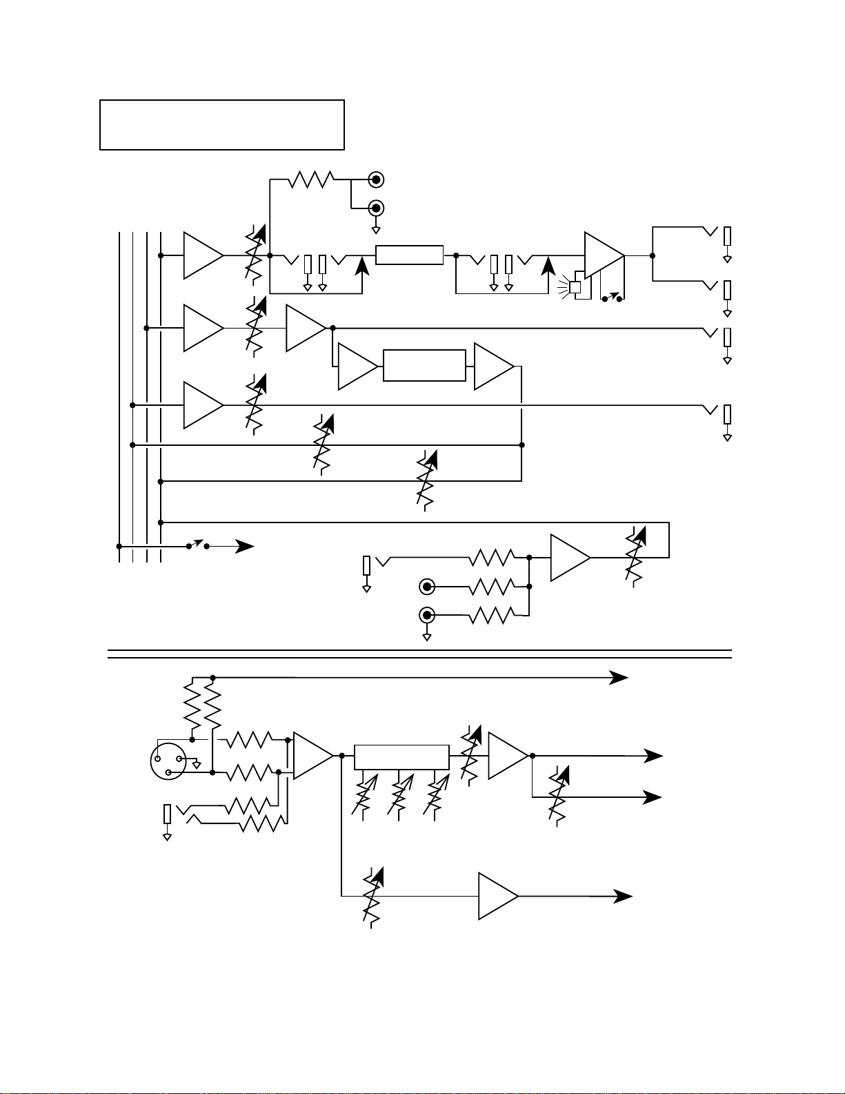
1-1 Block Diagram
MAIN
MONITOR
PHANTOM
EFFECTS/REVERB
MAIN
MASTER
EFF./REV.
SEND LEVEL
OUTPUT
MONITOR
MASTER
MAIN
GEQ
INPUT
REVERB RETURN
TO MONITOR
L
TAPE
OUTPUTS
R
GRAPHIC EQ
DIGITAL SIGNAL
PROCESSER
GEQ
OUTPUT
POWER
AMP INPUT
PEAK
PILOT LAMP
POWER
AMP
DELTACOMP
SWITCH
SPEAKER
OUTPUT
2 OHM
MINIMUM
TM
EFFECTS
OUTPUT
REVERB
FT. SW.
MONITOR
OUTPUT
MICROPHONE
+
21
LINE
PHANTOM
POWER
SWITCH
3
_
REVERB RETURN
TO MAIN
+15 VDC
AUX
INPUT
TAPE
INPUTS
L
R
MAIN
CHANNEL EQ
_
+
HIGH
MID
LOW
Signal path exclusive
of individual channel
AUX.
LEVEL
TO PHANTOM BUSS
TO MAIN BUSS
TO EFFECTS/
REVERB BUSS
EFF./REV.
Signal path typical
for each channel
TO MONITOR BUSS
MON.
Page 4

1. OVERVIEW.
1-2. INTRODUCTION.
The SR series integrated mixer/amplifiers have been
designed for easy setup and simple but versatile operation. Requiring only the addition of microphones and
speakers, the SR powered mixers are self-contained
sound reinforcement systems, with features and performance generally found only in units costing much
more.
not exceed 0.8 VRMS. Higher amplitude signals, such
as balanced line levels signals, may also be patched
into these jacks if an input pad is used (see Section 4-
4). The XLR jack is wired according to the following
standard:
Pin 1 is ground.
Pin 2 is the non-inverting (+) input.
Pin 3 is the inverting (-) input.
Signals at the XLR jacks experience 20 dB more gain
than those at the 1/4” channel input jacks.
Each input preamp channel provides a balanced XLR
MICROPHONE input with switchable phantom power
for condenser microphones, a 1/4’’ phone jack LINE
input, MAIN level control, LOW, MID, and HIGH frequency tone controls, MON. send control and an
EFF./REV. send control.
The master section features MAIN MASTER, MON.
MASTER, AUX. LEVEL, and DIGITAL REVERB and
EFFECTS level controls, a GRAPHIC EQUALIZER, and a
versatile patch bay.
The SR series mixers include DELTACOMP
tive compression system. DELTACOMP
TM
, an adap-
TM
is a high performance power amp limiter that senses amplifier
error due to clipping, and automatically reduces the
gain until the distortion is minimized. A front panel
yellow PEAK LED indicates power amp input limiting.
To make setup as simple as possible, the mixer,
graphic equalizer, and power amplifier are prepatched in a standard configuration that requires
plugging in only the microphones and speakers to be
“on the air.” To make the system as versatile as possible, this “normalized” patch may be bypassed by
using the inputs and outputs of the patch bay. These
allow the individual components of the system to be
used in various combinations, and for external equipment to be added into the system as the need arises.
2-2. CHANNEL CONTROLS.
2-2-1. CHANNEL MAIN CONTROL. The channel’s
MAIN control determines how much of the channel’s
signal is sent to the Main mixing buss and to the
EFF./REV. control. For best signal to noise ratio, this
control should be set relatively high; usual settings are
around 2 o'clock, except when input signal levels are
great enough to cause clipping. See Section 4-1-2.
2-2-2. CHANNEL TONE CONTROLS. The LOW, MID,
and HIGH controls on each channel may be adjusted
to enhance the qualities of its particular audio signal
and to control excessive boominess or sibilance (“s”
sounds) by using the LOW, MID, and HIGH controls.
When these controls are at 0 (straight up), the channel
is “flat” (no frequencies cut or boosted). The most natural sound is achieved by avoiding extreme tone control settings.
2-2-3. EFF./REV. CONTROL. This control determines
how much signal from each channel goes onto the
Effects/Reverb buss. All signals on this buss are combined in the master mixer section, and sent both to the
EFF. OUTPUT jack and to the internal reverb system.
The EFF./REV. control is wired post MAIN control and
post-EQ; thus, the level and tone of the EFF./REV. signal are altered by the settings of the MAIN, LOW,
MID, and HIGH controls.
The SR Series has been designed to meet the needs of
professionals, and can be counted on to provide reliable service in the most demanding situations.
1-1. BLOCK DIAGRAM. The block diagram illustrates
the typical signal path for the SR series.
2. FRONT PANEL CONTROLS, JACKS AND LEDs.
2-1-1. LINE INPUTS. The 1/4” phone jacks are
intended for high impedance balanced or unbalanced
inputs whose amplitude is under 8 VRMS. This would
include instrument and line level signals. When used
as a balanced input, the tip connection of the 1/4”
jack is the non-inverting (+) input and the ring connection is the inverting (-) input.
2-1-2. MICROPHONE INPUTS. The three-pin audio
connectors (often called “XLR” or “Cannon” connectors) on the front panel are intended for balanced
input signals from low impedance microphones. To
avoid clipping in the input stage, signal levels should
2-2-4. MON. CONTROL. The MON. control determines how much of a channel’s signal is sent to the
Monitor buss. This allows a separate mix to be created for stage monitoring. The control is wired preMAIN control and pre-EQ; thus, the monitor signal is
independent of other channel controls.
2-3. MASTER SECTION CONTROLS.
2-3-1. MAIN MASTER LEVEL CONTROL. This is the
master level control for the main mix. It controls the
signal level present at the MAIN OUT jack, if nothing
is patched into the EQ. IN jack or the PWR. AMP
INPUT jack. The MAIN MASTER control also determines the graphic equalizer and power amplifier input
levels.
2-3-2. MONITOR MASTER LEVEL CONTROL. This is
the master level control for the monitor mix. It controls the signal level present at the MONITOR OUTPUT
jack.
Page 5

2-3-3. REVERB RETURN TO MAIN CONTROL. This
control determines how much of the signal from the
reverb system is added or returned to the main mix.
When the LED is illuminated, the phantom power is
on. The 15 volts used for phantom power will run
nearly all condenser microphones.
2-3-4. REVERB RETURN TO MONITOR CONTROL.
Determines how much of the signal from the reverb
system is added to the monitor mix. Many vocalists
like to hear some reverb on their voices in the monitor
system; be aware that reverb in the monitors increases
the likelihood of feedback in the monitor system due
to increased gain.
2-3-5. EFF./REV. SEND LEVEL CONTROL. The mix
created by the settings of the channel EFF./REV. controls appears at the EFF. OUPUT jack, as well as being
sent to the reverb system. The signal level at the EFF.
OUTPUT jack is adjusted by the individual channel
EFF./REV. controls, and the EFF./REV. SEND LEVEL
master control.
2-3-6. AUX. LEVEL CONTROL. Signals patched into
the AUX. INPUT jack and / or the TAPE INPUTS are
sent to the Main buss via the AUX. LEVEL control. This
control determines how much of the AUX. INPUT signal appears in the main mix.
2-3-7. GRAPHIC EQUALIZER. The 9 band graphic
equalizer consists of active band pass / band reject filters spaced at octave intervals. The lowest frequency
filter is centered at 63Hz while the highest frequency
filter is centered at 16kHz. All others are centered on
the frequencies indicated below their sliders. Moving
the sliders up or down boosts or cuts the gain at the
indicated frequencies. This allows the sound engineer
to suppress feedback by compensating for room resonances encountered in live sound reinforcement applications. The EQ controls are accurately scaled in dB to
indicate the amount of cut or boost applied at each
frequency.
NOTE: It is possible for distortion to occur in the
Graphic Equalizer if excessive attenuation is used (slider well below center) while also trying to achieve significant level within the attenuated bands.
2-3-8. DIGITAL REVERB AND EFFECTS CONTROLS.
The internal DSP (Digital Signal Processor) system provides 126 different types of reverb and effects. These
are selected by the two rotary switch controls located
in the DIGITAL REVERB and EFFECTS section of the
front pannel. These two controls work together to
select and modify each reverb sound or effect algorithm. When the bottom switch chooses one of the
fourteen reverb selections, the top switch chooses the
reverb or delay time. When the bottom switch is in the
SPECIAL EFFECTS setting, the top switch chooses the
special effects algorithm. This is indicated by the pannel graphics, which show light and dark colored sections.
2-3-9. PHANTOM POWER (Select Switch and
Indicator LED). Engaging the switch applies 15 volts of
phantom power to all the XLR microphone input connectors for powering electret condenser microphones.
PHANTOM POWER LED. The green LED is the “phantom power on” indicator.
2-3-10. DELTACOMP
TM
. The yellow DELTACOMP
TM
LED comes on when excessive signal levels are being
sent to the power amp. It illuminates on signal peaks
that cause clipping (distortion) with DELTACOMP
activated, or for signal peaks that cause DELTACOMP
to reduce power amp input level (DELTACOMP
TM
not
TM
active). If the limiter is on for a large percentage of the
time, the dynamic range of the system is reduced and
the overall sound suffers; for this reason, level controls
should be adjusted so that the LIMIT light only flashes
on occasional signal peaks.
DELTACOMP
engaging the DELTACOMP
TM
SWITCH. DELTACOMPTMis activated by
TM
SWITCH.
2-3-11. POWER LED. The red POWER LED is the front
panel “power on” indicator.
2-4. PATCH BAY.
2-4-1. MAIN OUTPUT. Signals from each of the
channels are combined with AUX. and TAPE INPUTS
and the REVERB RETURN TO MAIN signal to form the
final main mix. The overall level of the mix is controlled by the MAIN MASTER control and this mix
appears at the MAIN OUTPUT jack. The mix is also
normally passed on to the GRAPHIC EQUALIZER and
to the power amplifier (see Sections 2-4-5 and 2-4-9).
Inserting a plug into the MAIN OUTPUT jack does not
interrupt the normal signal flow. It can be used for
inserting signal processing equipment into the signal
path (see Section 4-5), using the MAIN OUTPUT as a
send, and the GEQ INPUT as a return.
2-4-2. MONITOR OUTPUT. Signals present on the
Monitor buss are combined in the monitor summing
amplifier and sent to the MONITOR OUTPUT jack.
The signal level present at this output is determined by
the MONITOR MASTER control.
2-4-3. EFF. OUTPUT / REVERB FOOTSWITCH. Signals
present on the Effects/Reverb buss are mixed in the
Effects/Reverb summing amplifier. This mix is sent
both to the Reverb driver and to the EFF. OUTPUT
jack. Thus the mix created by the settings of the
EFF./REV. level controls on each of the preamp channels is present at the EFF. OUTPUT jack. The overall
level at this output is determined by the master mix
section EFF./REV. SEND LEVEL control. This output
may be used to drive external effects (echo units,
phase shifters, flangers, digital delays, etc.). The
return signal from the effect may be patched into the
mixer through the AUX. INPUT jack, or by way of a
preamp channel 1/4” input jack. Use of a preamp
channel as a return gives you the ability to shape the
frequency response of the signal; however, care must
be taken to insure that the EFF./REV. control on that
TM
Page 6

channel is turned all the way down - otherwise a feedback loop will exist which could cause oscillation and
possible damage to speakers. Care must be taken to
insure that the amplitude of the return signal is not too
great for the preamp channel input. An input pad
may be used if needed.
REVERB FOOTSWITCH. The Digital Reverb and Effects
processer can be defeated by inserting an optional
footswitch into the REVERB FOOTSWITCH jack. This
allows the Reverb and Effects to be turned off and on
remotely.
2-4-4. GEQ. OUTPUT. The output of the GRAPHIC
EQUALIZER is present at the GEQ. OUTPUT jack;
inserting a plug into this jack does not interrupt the
normal signal path. The jack is useful for patching
more power amplifiers into the system, for post-equalizer recording and for inserting signal processing
equipment (limiters, parametric equalizers, etc.)
between the equalizer and the power amplifier (see
Section 4-5).
2-4-5. GEQ. INPUT. The GRAPHIC EQUALIZER is
prepatched to the main output signal. However, the
GEQ. INPUT jack allows this “normalized” patch to be
defeated; inserting a 1/4” phone plug into the jack
disconnects the equalizer from the main signal and
instead connects it to any signal carried by the phone
plug. This allows the equalizer to be patched to other
SR outputs or to other pieces of audio equipment.
2-4-6. AUX. INPUT. This input is generally used as a
return from an external signal processing device
(flanger, phase shifter, etc.). Signals present at this
input are routed to the Main buss by way of the AUX.
LEVEL control. In emergencies, it is possible to use the
AUX. INPUT as a line level preamp channel, although
it lacks the preamp channel’s equalization, monitor,
and effects sends.
2-4-7. TAPE INPUTS. Patching the output of a stereo
tape deck into the two phono (RCA) jacks produces a
monophonic signal in the main mix. This is useful for
playing music during breaks in the performance, or for
performances where prerecorded music is required.
The TAPE INPUTS signal level is controlled by the AUX.
LEVEL control.
2-4-8. TAPE OUTPUTS. connecting the two phono
(RCA) TAPE OUTPUTS to a tape deck’s recording inputs
allows monophonic signal from the MAIN OUTPUT to
be recorded. The signal present at the TAPE OUTPUTS
is pre-GRAPHIC EQUALIZER and its level is determined
by the MAIN MASTER control.
2-4-9. PWR. AMP INPUT. Under normal circumstances, the power amplifier receives its input from the
GRAPHIC EQUALIZER. However, by inserting a 1/4”
phone plug into the PWR. AMP INPUT jack, the normal
signal path is broken and any signal carried by the
phone plug becomes the power amplifier’s input. This
3-1
3-1
3-2
REAR PANEL
SERIAL NUMBER
TYPE: PR 179
c
b
b
520 WATTS
2 OHM
MINIMUM
TOTAL
c
SPEAKER
OUTPUTS
POWER
e
d
FENDER MUSICAL INSTRUMENTS CORP.,
CAUTION: CHASSIS SURFACE HOT
WARNING: TO REDUCE THE RISK OF FIRE OR
ELECTRIC SHOCK, DO NOT EXPOSE THIS EQUIPMENT
AVIS: RISQUE DE CHOC ELECTRIQUE NE PAS OUVRIR
ATTENTION: SUPERFICIE DE CHASSIS CHAUDE
ON
OFF
MODEL
SR6520PD
DSP POWERED MIXER
A PRODUCT OF:
CORONA, CA 91720
MADE IN U.S.A.
TO RAIN OR MOISTURE
CAUTION:
RISK OF ELECTRIC SHOCK
DO NOT OPEN
INPUT POWER
INFO
1200W
3-3
WARNING:
DO NOT ALTER THE
AC (MAINS) PLUG.
Page 7

allows the power amplifier to be used independently
from the rest of the SR powered mixer. Possible uses
of this feature include dedicating the power amp to
the monitor system while employing an auxiliary
power amplifier for the mains, or using the SR power
amp as one of the two power amplifiers in a biamped
system (this would require the addition of an external
crossover). See Section 4-5.
3. REAR PANEL
3-1. SPEAKER OUTPUT JACKS(In Parallel). These are
the speaker outputs for the built-in power amplifier.
Do not connect loads with impedances lower than 2
ohms to the SPEAKER OUTPUT, as this may result in
amplifier overheating which will cause the SR mixer to
eventually self protect, “turning off” for a period of
time. (To calculate the speaker impedance, see Section
4-3-2.) In addition, be sure that the speaker cable
you use is of adequate gauge; otherwise, power will
be lost in the wire instead of being delivered to the
speaker.
3-2. POWER SWITCH. AC Power to the SR powered
mixer is turned on and off by a rocker switch located
on the back panel. If you have any external signal
processing devices patched to the system, turn them
on first to avoid pops in the loudspeakers. Also, when
you turn on the mixer, make sure that the main fader
is down - this eliminates the risk of the system immediately feeding back when it is turned on, and also
minimizes turn-on-pops.
3-3. POWER CORD. WARNING! Do not remove the
grounding prong of the AC plug. To do so risks exposure to potentially lethal voltages and voids the warranty. DO NOT ALTER THE AC (MAINS) PLUG.
4. SETUP AND OPERATION.
FIGURE 1 illustrates the simplest way to set up your PA
system.
4-1. INITIAL CONTROL SETTINGS. When you first set
up the sound system, initial settings are critical for
arriving at a satisfactory mix quickly. Often, to the
distress of many sound engineers, the show must
begin without a preliminary sound check. The following recommendations should help to alleviate some of
the engineer’s headaches.
4-1-1 TYPICAL PRESETS. Set the channel HIGH, MID,
and LOW frequency controls to their mid positions,
and also set the GRAPHIC EQUALIZER to its mid or flat
position. Set the MAIN MASTER and MONITOR MASTER controls to around the 1o'clock position. Set all
other controls to zero.
4-1-2 MAIN CONTROL. Adjust the MAIN controls to
the approximate level you desire, with a mix that you
feel will be acceptable.
4-1-3. MON. CONTROLS. Most groups like to hear
their voices in the monitors; some also like to hear
certain instruments as well (keyboard, acoustic guitar,
and so forth). A good initial MON. control setting is 5
(straight up). Assuming that the various vocalists use
similar miking techniques and sing at similar volumes,
the levels appearing in the monitor mix should be fairly matched. Further adjustments can be made as
needed.
4-1-4. CHANNEL TONE CONTROLS. Most vocal,
keyboard, and other full range signals are best left flat
(controls at 0, or straight up). For signals having a
great deal of low frequency content, such as drums
and bass guitars, the LOW control should
initially be backed off slightly (rotated to the left) from
the 0 position to reduce boominess. Naturally, all
controls should be set to achieve the most pleasing
sounds, but the settings listed above should help in
achieving good results quickly. In general, extreme
settings cause the sound to be unnatural and should
be avoided.
4-1-5. GRAPHIC EQUALIZER. Start out with equalizer
set “flat” (O dB). On the SR mixers, the 63 Hz control
may be set initially 3 to 6 dB below the center position,
since excessive low frequencies rob power from the
rest of the system and low-end feedback can damage
loudspeakers.
4-2. USING THE GRAPHIC EQUALIZER TO ELIMINATE ACOUSTIC FEEDBACK.
4-2-1. THE CAUSE OF ACOUSTIC FEEDBACK.
Acoustic feedback in a sound system is the result of
coupling between the speakers and microphones. The
microphones will always pick up a certain amount of
signal from the speakers; how much they pick up
depends on the room acoustics, the frequency
response of the microphones and speakers, and the
mic and speaker placement. If the received signal is
amplified enough (in the mixer and power amplifier),
the speakers will continue to produce the signal, and
the characteristic howl of acoustic feedback will begin.
This feedback will occur at the frequency which
receives the largest amount of gain from the sound
system (including the room). If the signal can be
attenuated at that frequency, more gain can be added
to the rest of the signal frequencies before feedback
occurs. This is the primary role of an equalizer in a
sound system.
4-2-2. TYPICAL PROCEDURE FOR ROOM EQUALIZATION.
1. Set up your entire sound system the way it will be
used, including all auxiliary equipment, and adjust it
the way you would normally use it. If feedback occurs
during setup, reduce the gain of the mixer with the
MAIN and MONITOR level controls. Follow the procedure outlined in the paragraphs below, first for the
main system and then for the monitors (assuming you
are using an equalizer in your monitor system, which
is highly recommended).
2. Set the controls on the GRAPHIC EQUALIZER to the
“flat” position, indicated as “0 dB” on the panel.
3. Slowly increase the output level (using the appropriate level control) until the sound system is on the
threshold of feedback - a ringing sound will occur
when you tap on the microphones.
Page 8

4. Slowly attenuate the Equalizer control which has
the greatest effect on reducing the ringing. This will
take some trial and error - the first ringing usually
occurs between 1 kHz and 4 kHz. Continue until the
ringing has stopped.
5. Again, slowly increase the output level control until
the system is on the verge of feeding back. Adjust the
equalizer to remove the potential feedback. Continue
this procedure until you have achieved sufficient gain
for your application or until the equalizer becomes
ineffective at removing the ringing. It is best to back
off the gain once maximum gain before feedback has
been established. Avoid extreme settings or settings
which require a large amount of cut in the middle frequency bands, as such settings impair intelligibility.
• Use the highest quality patch cords available
and keep them as short as possible.
• Avoid patching a buss output back into its input.
An example of this is patching a phase shifter
from the EFF. OUTPUT / REVERB FOOTSWITCH
and returning it to the input of a channel which
has its EFF./REV. control turned up. Doing so
may result in oscillation (possibly inaudible)
that can damage loudspeakers and create distortion.
• Do not use a mic level or instrument level effect
(such as an effect intended for guitar) with a line
level signal (such as the Main or Graphic EQ
output).
6. “Fine tune” the equalizer settings as the performance progresses to achieve the best overall sound
from the system.
4-3. CORDS AND CABLES.
4-3-1. MICROPHONE CORDS. On the SR mixers, use
balanced two-conductor shielded cable for all long
runs. Balanced systems are capable of rejecting noise
introduced from such sources as cash registers, electric
motors and triac-controlled lights. If a balanced cable
is connected to an unbalanced output (e.g., a keyboard mixer output) or microphone, use a balancing
transformer close to the unbalanced device. This
ensures maximum common-mode noise rejection for
the entire system.
If you have no choice and must use unbalanced
cables, use the shortest cables possible and keep them
away from AC power mains, lighting cables and
speaker wires. If you want the quietest system possible, you should follow these rules with balanced lines
as well.
4-3-2. SPEAKER CABLES. Use two conductor zip cord
to connect the amplifier outputs to your speakers. The
gauge of the wire is important; wire that is too light in
gauge consumes power (the power from the amplifier
heats up the wire for your particular situation). To calculate your speaker impedance, use Figure 3.
4-4. INPUT PADS. If input signal levels are too great,
the input stage may be overdriven and cause distortion. The solution in such cases is to use an input pad.
A 30 dB pad can be made by using a Switchcraft connector (part #S3FM) with the resistor network shown
in Figure 4.
4-5. PATCHING. Figures 5 through 8 show possible
ways of patching external equipment into the SR
mixer. They are by no means the only patches possible. If you want to try a patch that is not illustrated,
consult the Block Diagram to determine if your patch is
possible. When patching external equipment into the
signal chain, best results will be obtained by following
these rules:
5. UPKEEP AND SERVICE
The SR powered mixers have been designed to give
years of trouble free service. With a few precautions,
you can help to insure its continued reliable service.
• Do not obstruct the air vents on the rear panel.
• Transport the mixer with care.
• Periodically inspect the mixer for damage which
may occur during transportation.
• If you leave the mixer set up when you are not
using it, protect it from dust with a soft cover.
DO NOT SET FOOD OR BEVERAGE on the SR powered
mixer - this can not be overemphasized. Spilling a
drink can be the quickest way to ruin a potentiometer
(fader, level control, EQ control) or switch.
• When using the mixer protect it from
moisture (rain, sprinklers, beer, etc.)
• Periodically clean the mixer by wiping it
with a soft cloth and a small amount of furniture polish.
6. TROUBLESHOOTER'S CHECKLIST:
If the mixer is set up but does not function, check the
following items:
-Is the mixer power cord properly plugged into an
electrical outlet?
-Is there power at the outlet?
-Are the speakers properly hooked up to the
mixer?
-Are the proper controls turned up?
-Is the instrument turned up?
-Check all cables and wires.
If, after checking all of the above, the mixer is still not
performing correctly, consult your Fender Service
Dealer.
Page 9

7. SPECIFICATIONS
POWER AMPLIFICATION SECTION:
SR-6520PD / SR-8520PD
Part Number: 100V Version: 071-6521-270 / 071-8521-270
120V Version: 071-6521-200 / 071-8521-200
230V Version: 071-6521-260 / 071-8521-260
230V Version: 071-6521-240 / 071-8521-240 U.K.
240V Version: 071-6521-230 / 071-8521-230 AUST.
Type Specification: SR-6520PD: PR189
SR-8520PD: PR189
Power Specification: 100V Version: 100VAC, 50/60Hz, 1200W
120V Version: 120VAC, 60Hz, 1200W
230V Version: 230VAC, 50Hz, 1200W
240V Version: 240VAC, 50Hz, 1200W
Power Output: 520W RMS @ 2Ω
350W RMS @ 4Ω
Min. Load Impedance: 2Ω
Distortion at 520W: Less than .2% @ 1kHz into 2Ω
Input Sensitivity: 1.28V RMS
Input Impedance: 22kΩ
DELTACOMPTMRange: 20dB
PRE-AMPLIFIER SECTION:
LOW-Z Input Impedance: 1.82kΩ
HI-Z Input Impedance: 18.2kΩ
HI-Z Input Sensitivity for 520W: 55mV RMS
(MAIN MASTER and Channel
MAIN at maximum, all tone
controls and GEQ at "0"
detent, power amp at
520W, 4 Ω).
Channel Tone Controls: LOW +/– 15 dB at 100 Hz
MID +/– 15 dB at 750 Hz
HIGH +/– 15 dB at 10 kHz
Graphic Equalizer: +/– 12dB at 63, 125, 250, 500, 1k, 2k, 4k, 8k and
16 kHz.
PHYSICAL SPECIFICATIONS:
SR6520PD SR8520PD
Height: 10-7/16 Inches ( 26.5 cm ) Height: 10-7/16 Inches ( 26.5 cm )
Width: 23-5/8 Inches ( 60.0 cm ) Width: 27-5/8 Inches ( 70.2 cm )
Depth: 12 Inches ( 30.5 cm ) Depth: 12 Inches ( 30.5 cm )
Weight: 40.0 lbs. ( 18.2 kg ) Weight: 42.0 lbs. ( 19.1 kg )
WARNING: NO USER SERVICEABLE PARTS INSIDE. REFER SERVICING TO QUALIFIED PERSONNEL ONLY.
THIS EQUIPMENT MUST BE EARTH GROUNDED.
Page 10

2-3-11
2-3-10
2-3-8
2-3-4
2-3-6
2-3-8
2-3-5
2-4-8
ELECTRONICS
REVERB /
DELAY TIME
DELAY
DELAY
TRIPLE HIT
TAPE ECHO
DOUBLE HIT
-dB
76543
8-LONG
DEFEAT
REVERB
DELAY + REVERB
REGENERATION
POWER
TM
DELTACOMP
OFF
2
1-SHORT
DELAY
DEFEAT
DIGITAL REVERB and EFFECTS
ON
MULTI-TAP
DSP POWERED MIXER
GRAPHIC EQUALIZER
63 125 250 500 1K 2K 4K 8K 16K
9 9
6 6
3 3
0 0
3 3
6 6
12 12
+dB +dB
SR6520PD
POWER
PHANTOM
9 9
12 12
-dB
ON
OFF
BRIGHT
BRIGHT
DARK
LARGE HALL REV.
SMALL HALL REV.
SPECIAL
EFFECTS
REVERSE REVERB
MAX.
AUX. LEVEL
00
MAX.
00
TO MONITOR
REVERB RETURN
MAX.
TO MAIN
00
REVERB RETURN
BRIGHT
DARK
DARK
SMALL ROOM REV.
DARK
DELAYS
GATED REVERB
BRIGHT
LARGE ROOM REV.
BRIGHT
LARGE PLATE REV.
MAX.
EFF./REV.
00
SEND LEVEL
MAX.
MASTER
MONITOR
00
MAX.
MAIN
MASTER
00
DARK
DARK
SMALL PLATE REV.
TAPE
TAPE
BRIGHT
AUX.
PWR. AMP
GEQ
GEQ
EFF. OUTPUT
MONITOR
MAIN
OUTPUTS
INPUTS
INPUT
INPUT
INPUT
SYSTEM PATCH BAY
OUTPUT
REVERB
FOOTSWITCH
OUTPUT
OUTPUT
2-4-7
2-4-6
2-4-9
2-4-5
2-4-4
2-4-3
2-4-2
FRONT PANEL CONTROLS
2-2-3
CHANNEL CONTROLS
2-3-7
MAX.
EFF./REV.
00
2-2-2
+15
HIGH
-15
2-3-9
2-2-2
+15-15
MID
2-2-2
+15
LOW
-15
2-3-3
2-2-4
MAX.
00
MON.
2-3-1
2-2-1
MAIN
2-3-2
2-1-1
1
2-4-1
2-1-2
MICROPHONE
LINE
Page 11

FENDER MAIN
P.A. SPEAKERS
FIGURE 1
SPEAKER
OUT
MAX.
MAX.
MAX.
00
00
EFF./REV.
EFF./REV.
+15
-15
+15
-15
HIGH
HIGH
+15-15
+15-15
MID
MID
-15
-15
+15
+15
LOW
LOW
MAX.
MAX.
00
00
MON.
MON.
MAIN MAIN
2 5
1
LINE
MICROPHONE
LINE
MICROPHONE
3
LINE
MAX.
00
00
EFF./REV.
EFF./REV.
+15
-15
+15
-15
HIGH
HIGH
+15-15
+15-15
MID
MID
-15
-15
+15
+15
LOW
LOW
MAX.
MAX.
00
00
MON.
MON.
MAIN MAIN MAIN MAIN
4
MICROPHONE
LINE
LINE
MICROPHONE
GRAPHIC EQUALIZER
DSP POWERED MIXER
SR6520PD
MAX.
00
EFF./REV.
+15
-15
HIGH
+15-15
MID
-15
+15
LOW
MAX.
00
MON.
MICROPHONE
63 125 250 500 1K 2K 4K 8K 16K
+dB +dB
12 12
9 9
6 6
PHANTOM
POWER
3 3
0 0
3 3
6 6
9 9
OFF
12 12
ON
-dB
GRAPHIC EQUALIZER
MAX.
MAX.
00
00
REVERB RETURN
REVERB RETURN
TO MAIN
TO MONITOR
MAX.
MAX.
00
00
MAIN
MONITOR
MASTER
MASTER
MAIN
MONITOR
EFF. OUTPUT
OUTPUT
OUTPUT
REVERB
FOOTSWITCH
GEQ
OUTPUT
MAX.
00
EFF./REV.
+15
-15
HIGH
+15-15
MID
-15
+15
LOW
MAX.
00
MON.
6
MICROPHONE
LINE
00
AUX. LEVEL
00
SEND LEVEL
EFF./REV.
MAX.
MAX.
GEQ
INPUT
SYSTEM PATCH BAY
OFF
ON
DIGITAL REVERB and EFFECTS
MULTI-TAP
TRIPLE HIT
DOUBLE HIT
-dB
TAPE ECHO
DELAY + REVERB
REGENERATION
SPECIAL
EFFECTS
REVERSE REVERB
GATED REVERB
LARGE PLATE REV.
SMALL PLATE REV.
PWR. AMP
INPUT
DELTACOMP
DEFEAT
DEFEAT
REVERB
DELAYS
TM
POWER
ELECTRONICS
1-SHORT
2
3
DELAY
4
REVERB /
DELAY
DELAY TIME
5
DELAY
6
7
8-LONG
BRIGHT
SMALL HALL REV.
DARK
BRIGHT
LARGE HALL REV.
DARK
BRIGHT
SMALL ROOM REV.
DARK
DARK
BRIGHT
BRIGHT
LARGE ROOM REV.
DARK
DARK
BRIGHT
TAPE
TAPE
AUX.
INPUT
INPUTS
OUTPUTS
MONITOR
OUT
MICROPHONES
KEYBOARD
FENDER MODEL M-300
STAGE MONITOR AMPLIFIER
FENDER MONITORS
(MODEL 1272A,
1275A, 1282 Mk. II,
OR 1285 Mk. II).
Page 12

Speaker Wire Gage
100'-UP 8 10 12 14
50'-100' 10 12 14 16
*25'-50' 12 14 *16 18
10'-25' 14 16 18 18
0'-10' 16 18 18 18
Speaker Wire Length
2Ω 4Ω *8Ω16Ω
Speaker Impedance
1
Z
1
=
p
1.8 3.2 5.3 8
16Ω
1.6 2.7 4 5.3
8Ω
1.3 2 2.7* 3.2
4Ω*
1 1.3 1.6 1.8
2Ω
2Ω 4Ω 8Ω*16Ω
Cabinet B Impedance
Cabinet A Impedance
+
Z
1
...
Z
2n1
1
Z
CHART A
Impedance
+ -
Parallel
+
-
+
AB
*Example- The length of speaker wire
required is between 25 and 50 feet
and the speaker impedance is 8
ohms. The minimum recommended
gauge speaker wire is 16 gauge.
FIGURE 3
Impedance
A
-
B
FIGURE 2
CHART B
Series
+
+
-
Z
=
s
16Ω*
8Ω
4Ω
2Ω
Cabinet B Impedance
+ -
Cabinet A Impedance
ZZZ
+
2n1
18 20* 24 32
10 12 16 24
6 8 12 20
4 6 10 18
2Ω 4Ω*8Ω16Ω
...
*Example- Cabinet A is 8 ohms.
Cabinet B is 4 ohms. The total
impedance when connected in
parallel is = 1 = 2.7 ohms
181
+
4
FIGURE 4
SWITCHCRAFT
PIN 1
PIN 2
PIN 3
680
FEMALE
OHM
(to microphone)
30dB PAD
S3FM
22K
22K
*Example- Cabinet A is 4
ohms. Cabinet B is 16 ohms.
The total impedance when
connected in series is 4 + 16
= 20 ohms.
PIN 1
PIN 2
PIN 3
150
OHM
MALE
(to mixer)
ALL RESITORS ARE 5%
1/4 WATT
Page 13

FIGURE 5
AN ILUSTRATION USING AN AUXILIARY POWER AMP AND ADDITIONAL SPEAKERS ON THE MAINS FOR
MORE POWER, AND THE BUILT IN SR POWER AMP TO POWER UP TO 4 STAGE MONITOR LOUDSPEAKERS.
BUILT IN GEQ NOW WORKS ON MONITORS.
SPEAKER
OUT
4Ω
total
Fender Monitors
(1272A 16Ω , 1275A 16Ω
1282 Mk.II 8Ω or 1285 Mk.II 8Ω )
MAX.
00
00
EFF./REV.
EFF./REV.
+15
-15
-15
HIGH
HIGH
+15-15
MID
-15
-15
+15
LOW
MAX.
00
00
MON.
MON.
MAIN MAIN
2 5
1
LINE
MICROPHONE
LINE
MAX.
MAX.
00
EFF./REV.
+15
-15
+15
HIGH
+15-15
+15-15
MID
MID
-15
+15
+15
LOW
LOW
MAX.
MAX.
00
MON.
MAIN MAIN MAIN MAIN
4
3
LINE
MICROPHONE
MICROPHONE
LINE
00
EFF./REV.
-15
-15
00
GRAPHIC EQUALIZER
FENDER SPL 6000 OR
SPL 9000 POWER AMPLIFIER
DSP POWERED MIXER
63 125 250 500 1K 2K 4K 8K 16K
+dB +dB
12 12
9 9
6 6
3 3
0 0
3 3
6 6
9 9
12 12
-dB
GRAPHIC EQUALIZER
MAX.
MAX.
00
00
REVERB RETURN
REVERB RETURN
TO MAIN
TO MONITOR
MAX.
MAX.
00
00
MAIN
MONITOR
MASTER
MASTER
MONITOR
EFF. OUTPUT
OUTPUT
REVERB
FOOTSWITCH
GEQ
OUTPUT
HIGH
MID
LOW
MON.
MICROPHONE
MAX.
MAX.
00
EFF./REV.
+15
+15
-15
HIGH
+15-15
+15-15
MID
-15
+15
+15
LOW
MAX.
MAX.
00
MON.
LINE
MICROPHONE
SR6520PD
MAX.
00
EFF./REV.
PHANTOM
POWER
+15
-15
HIGH
+15-15
OFF
MID
ON
-15
+15
LOW
MAX.
00
MON.
6
MAIN
OUTPUT
LINE
MICROPHONE
MAIN OUT
Power amp input (dual mono mode)
SPL 6000
ELECTRONICS
00
AUX. LEVEL
00
SEND LEVEL
EFF./REV.
MAX.
MAX.
GEQ
INPUT
SYSTEM PATCH BAY
DELTACOMP
OFF
ON
DIGITAL REVERB and EFFECTS
DEFEAT
MULTI-TAP
DELAY
TRIPLE HIT
DELAY
DOUBLE HIT
DELAY
-dB
TAPE ECHO
DELAY + REVERB
DEFEAT
REVERB
REGENERATION
SPECIAL
EFFECTS
REVERSE REVERB
DELAYS
GATED REVERB
DARK
LARGE PLATE REV.
BRIGHT
DARK
SMALL PLATE REV.
BRIGHT
PWR. AMP
INPUT
TM
POWER
ELECTRONICS
1-SHORT
2
3
4
REVERB /
DELAY TIME
5
6
7
8-LONG
BRIGHT
SMALL HALL REV.
DARK
BRIGHT
LARGE HALL REV.
DARK
BRIGHT
SMALL ROOM REV.
DARK
BRIGHT
LARGE ROOM REV.
DARK
TAPE
AUX.
INPUT
INPUTS
SPEAKER
OUTPUTS
TAPE
OUTPUTS
8Ω
8Ω
Fender
Main P.A.
Speakers
4Ω
total
8Ω
4Ω
total
8Ω
Page 14

FIGURE 6
PATCHING AN EFFECT BETWEEN THE EFFECTS OUT AND THE AUX. IN.
DSP POWERED MIXER
MAX.
MAX.
MAX.
00
00
EFF./REV.
EFF./REV.
-15
-15
HIGH
HIGH
MID
MID
-15
-15
LOW
LOW
00
00
MON.
MON.
MAIN MAIN
MAIN MAIN
1
1
LINE
LINE
MICROPHONE
MICROPHONE
MAX.
00
00
EFF./REV.
EFF./REV.
+15
+15
-15
+15
+15
-15
HIGH
HIGH
+15-15
+15-15
+15-15
+15-15
MID
MID
+15
+15
+15
+15
-15
-15
LOW
LOW
MAX.
MAX.
MAX.
MAX.
00
00
MON.
MON.
2 5
2 5
LINE
LINE
MICROPHONE
MICROPHONE
MAX.
MAX.
MAX.
00
00
00
00
EFF./REV.
EFF./REV.
EFF./REV.
EFF./REV.
+15
-15
-15
+15
-15
-15
HIGH
HIGH
HIGH
HIGH
+15-15
+15-15
MID
MID
MID
MID
+15
+15
-15
-15
-15
-15
LOW
LOW
LOW
LOW
MAX.
MAX.
00
00
00
00
MON.
MON.
MON.
MON.
MAIN MAIN MAIN MAIN
MAIN MAIN MAIN MAIN
4
4
3
3
LINE
LINE
MICROPHONE
MICROPHONE
LINE
LINE
MICROPHONE
MICROPHONE
MAX.
MAX.
MAX.
00
00
EFF./REV.
EFF./REV.
+15
+15
-15
+15
+15
-15
HIGH
HIGH
+15-15
+15-15
+15-15
+15-15
MID
MID
+15
+15
+15
+15
-15
-15
LOW
LOW
MAX.
MAX.
MAX.
MAX.
00
00
MON.
MON.
LINE
LINE
MICROPHONE
MICROPHONE
SR6520PD
SR6520PD
MAX.
MAX.
00
00
EFF./REV.
EFF./REV.
PHANTOM
PHANTOM
POWER
POWER
+15
-15
+15
-15
HIGH
HIGH
+15-15
+15-15
OFF
OFF
MID
MID
ON
ON
+15
+15
-15
-15
LOW
LOW
REVERB RETURN
REVERB RETURN
MAX.
MAX.
00
00
MON.
MON.
6
6
LINE
LINE
MICROPHONE
MICROPHONE
MAIN
MAIN
OUTPUT
OUTPUT
DSP POWERED MIXER
63 125 250 500 1K 2K 4K 8K 16K
63 125 250 500 1K 2K 4K 8K 16K
+dB +dB
+dB +dB
12 12
12 12
9 9
9 9
6 6
6 6
3 3
3 3
0 0
0 0
3 3
3 3
6 6
6 6
9 9
9 9
12 12
12 12
-dB
-dB
GRAPHIC EQUALIZER
GRAPHIC EQUALIZER
MAX.
MAX.
MAX.
00
00
00
00
MAX.
00
00
REVERB RETURN
REVERB RETURN
TO MONITOR
TO MONITOR
TO MAIN
TO MAIN
MAX.
MAX.
MAX.
MAX.
00
00
MAIN
MONITOR
MAIN
MONITOR
MASTER
MASTER
MASTER
MASTER
MONITOR
EFF. OUTPUT
MONITOR
GEQ
EFF. OUTPUT
GEQ
OUTPUT
REVERB
OUTPUT
OUTPUT
REVERB
OUTPUT
FOOTSWITCH
FOOTSWITCH
00
00
AUX. LEVEL
AUX. LEVEL
00
00
EFF./REV.
EFF./REV.
SEND LEVEL
SEND LEVEL
SYSTEM PATCH BAY
SYSTEM PATCH BAY
-dB
-dB
MAX.
MAX.
MAX.
MAX.
GEQ
GEQ
INPUT
INPUT
DELTACOMP
DELTACOMP
OFF
OFF
ON
ON
DIGITAL REVERB and EFFECTS
DIGITAL REVERB and EFFECTS
DEFEAT
DEFEAT
MULTI-TAP
MULTI-TAP
DELAY
DELAY
TRIPLE HIT
TRIPLE HIT
DELAY
DELAY
DOUBLE HIT
DOUBLE HIT
DELAY
DELAY
TAPE ECHO
TAPE ECHO
DELAY + REVERB
DELAY + REVERB
DEFEAT
DEFEAT
REVERB
REVERB
REGENERATION
REGENERATION
SPECIAL
SPECIAL
EFFECTS
EFFECTS
REVERSE REVERB
REVERSE REVERB
DELAYS
DELAYS
GATED REVERB
GATED REVERB
DARK
DARK
LARGE PLATE REV.
LARGE PLATE REV.
BRIGHT
BRIGHT
DARK
DARK
SMALL PLATE REV.
SMALL PLATE REV.
BRIGHT
BRIGHT
PWR. AMP
PWR. AMP
INPUT
INPUT
INPUT
INPUT
TM
TM
AUX.
AUX.
POWER
POWER
1-SHORT
1-SHORT
8-LONG
8-LONG
BRIGHT
BRIGHT
SMALL HALL REV.
SMALL HALL REV.
DARK
DARK
BRIGHT
BRIGHT
LARGE HALL REV.
LARGE HALL REV.
DARK
DARK
BRIGHT
BRIGHT
SMALL ROOM REV.
SMALL ROOM REV.
DARK
DARK
BRIGHT
BRIGHT
LARGE ROOM REV.
LARGE ROOM REV.
DARK
DARK
ELECTRONICS
ELECTRONICS
2
2
3
3
4
4
REVERB /
REVERB /
DELAY TIME
DELAY TIME
5
5
6
6
7
7
TAPE
TAPE
TAPE
TAPE
INPUTS
OUTPUTS
INPUTS
OUTPUTS
EFFECTS OUT
AUX. IN
INPUT OUTPUT
EFFECTS
FIGURE 7
PATCHING AN EFFECT BETWEEN THE EFFECTS OUT AND CHANNEL INPUT.
IMPORTANT: EFFECTS/REVERB
TURNED ALL THE WAY DOWN (OFF).
MAX.
00
EFF./REV.
-15
HIGH
MID
-15
LOW
00
MON.
MAIN MAIN
1
LINE
MICROPHONE
MAX.
00
EFF./REV.
+15
+15
-15
HIGH
+15-15
+15-15
MID
+15
+15
-15
LOW
MAX.
MAX.
00
MON.
2 5
LINE
MICROPHONE
MAX.
MAX.
00
00
EFF./REV.
EFF./REV.
+15
-15
-15
HIGH
HIGH
+15-15
MID
MID
+15
-15
-15
LOW
LOW
MAX.
00
00
MON.
MON.
MAIN MAIN MAIN MAIN
4
3
LINE
MICROPHONE
LINE
MICROPHONE
MAX.
00
EFF./REV.
+15
+15
-15
HIGH
+15-15
+15-15
MID
+15
+15
-15
LOW
MAX.
MAX.
00
MON.
LINE
MICROPHONE
SR6520PD
MAX.
00
EFF./REV.
PHANTOM
POWER
+15
-15
HIGH
+15-15
OFF
MID
ON
+15
-15
LOW
REVERB RETURN
MAX.
00
MON.
6
LINE
MICROPHONE
MAIN
OUTPUT
DSP POWERED MIXER
63 125 250 500 1K 2K 4K 8K 16K
+dB +dB
12 12
9 9
6 6
3 3
0 0
3 3
6 6
9 9
12 12
-dB
GRAPHIC EQUALIZER
MAX.
00
00
MAX.
00
REVERB RETURN
TO MONITOR
TO MAIN
MAX.
MAX.
00
MAIN
MONITOR
MASTER
MASTER
MONITOR
EFF. OUTPUT
GEQ
OUTPUT
REVERB
OUTPUT
FOOTSWITCH
00
AUX. LEVEL
00
EFF./REV.
SEND LEVEL
SYSTEM PATCH BAY
-dB
MAX.
MAX.
GEQ
INPUT
DELTACOMP
OFF
ON
DIGITAL REVERB and EFFECTS
DEFEAT
MULTI-TAP
DELAY
TRIPLE HIT
DELAY
DOUBLE HIT
DELAY
TAPE ECHO
DELAY + REVERB
DEFEAT
REVERB
REGENERATION
SPECIAL
EFFECTS
REVERSE REVERB
DELAYS
GATED REVERB
DARK
LARGE PLATE REV.
BRIGHT
DARK
SMALL PLATE REV.
BRIGHT
PWR. AMP
INPUT
INPUT
TM
AUX.
POWER
1-SHORT
8-LONG
BRIGHT
SMALL HALL REV.
DARK
BRIGHT
LARGE HALL REV.
DARK
BRIGHT
SMALL ROOM REV.
DARK
BRIGHT
LARGE ROOM REV.
DARK
ELECTRONICS
2
3
4
REVERB /
DELAY TIME
5
6
7
TAPE
TAPE
INPUTS
OUTPUTS
CHANNEL INPUT EFFECTS OUT
INPUTOUTPUT
EFFECTS
A Product of:
Fender Musical Instruments Corp.,
Corona, CA 91720
 Loading...