


3
250 Watts of Clear Stereo Sound
Custom Designed Loudspeakers Utilizing the latest in
High-Performance Speaker technology
Built-in Digital Reverb
VIP™ (Vocal Input Priority) Allows input one to
automatically override all other inputs when a signal is
present on input one
Four Mono Microphone / Line Inputs with XLR and
1/4” balanced inputs connections
Two Stereo Inputs with 1/4” and RCA Connections
Switch Mode Power Supply Allows Use Anywhere In
The World
Everything You Need To Get Started:
– Passport Mixer Amplifier
– Two Dynamic Microphones & Cables
– Two Speaker Cables, 9m (30’)
– IEC Power Cable
– Two, State of the Art, Full-Range Speaker
Enclosures
– Full transportation enclosure
This symbol warns the user of dangerous
voltage levels localized within the enclosure.
This symbol advises the user to read all
accompanying literature for safe operation of
the unit.
Congratulations on your purchase of a Fender Passport
PD-250 high performance, self-contained portable audio
system. Your Passport includes everything you will need
for great sound… Anywhere.
Carry your Passport as you would a large sized suit case.
Flip open the speaker latches, and you’ll discover two fullrange speaker cabinets, a powered mixer, dynamic
microphones, plus all the cables you need to get started.
Use your Passport to amplify voices, musical instruments,
computer sound cards, CD’s, tape playback and more.
Passport’s quick and easy set-up, its ability to cover large
audiences and simple operation are the hallmarks of this
innovative product line.
The Passport’s control panel features four mono mic/line
inputs and two stereo channels (six channels total). The
stereo input channels can be used for either mono or
stereo operation allowing superb flexibility in input use.
Moreover, the revolutionary speaker technology in each
speaker enclosure deliver remarkably clean, full range
sound with exceptional audience coverage and
remarkable feedback rejection. The self-powered mixer
provides a total of 250 watts of high quality stereo sound.
For vocal operation, the Passport’s VIP (Vocal Input
Priority) feature can be used to reduce or “duck” the
background music level as you begin to speak and then
restore your background music when you have finished
speaking. Experiment with the tone controls, digital reverb
and speaker placement and discover the Passport’s
incredible power and versatility.
IMPORTANT SAFEGUARDS:
– WARNING : TO PREVENT DAMAGE, FIRE OR
SHOCK HAZARD, DO NOT EXPOSE THIS UNIT TO
RAIN OR MOISTURE.
– NO USER SERVICEABLE PARTS INSIDE, REFER
SERVICING TO QUALIFIED PERSONNEL ONLY.
– THIS UNIT MUST BE EARTH GROUNDED.
INTRODUCTION
Fender Passpor
Fender Passpor
t PD-250
t PD-250
Deluxe Por
Deluxe Por
table Sound System
table Sound System
4
SAFETY PRECAUTIONS
The Fender Passport sound system is supplied
with a detachable power cable with an IEC
female connector and a male AC connector.
Depending on the territory in which the
Passport system is purchased, the power cable will be
supplied with one of a number of male AC connectors to
accommodate the different safety and code requirements
of specific countries. All AC cables supplied with Passport
products are three pin grounded types.
Under no circumstances should the ground (earth) pin be
disconnected or removed.
Your Passport System features a Switch-Mode-PowerSupply designed to operate on any AC voltage and line
frequency to convert AC power with maximum efficiency.
When traveling abroad with the Passport system, as a
standard precaution, always check the local voltage and
set the voltage selector switch located adjacent to the
power input socket on the rear of the mixer / amplifier to
the appropriate operating range. This check must be
performed before connecting the power cable. The
Fender Passport has two range settings: 115 V or 230 V.
Failure to select the appropriate voltage range will cause
the unit to go into protect mode, void any warranty and
may cause damage to the unit.
For example, The United States of America is
standardized at 117 volts / 60 Hz, Japan operates on
100 volts / 50 Hz. For both of these countries the range
selector must be set to 115 V. Countries in the EEC have
standardized at 230 volts / 50 Hz., however, there are
different types of AC plugs used. For all these countries
the selector should be at the 230 V position. When using
plug adapters or operating in a territory other than the one
in which the unit was purchased, take great care to
comply with local safety requirements and electrical codes
of practice.
If you are not sure of the local voltage, wiring codes &
colors, AC grounding, or correct procedures for
connection, consult a qualified technician.
Warning
Under no circumstances should the ground pin
on the Passport or on any of your electrical
equipment be lifted (cut off or disconnected).
By following the correct procedures and safety
precautions, risks of severe shock hazard can be minimized. Best of all, avoid operating the system in conjunction with ungrounded or improperly grounded
electrical equipment.
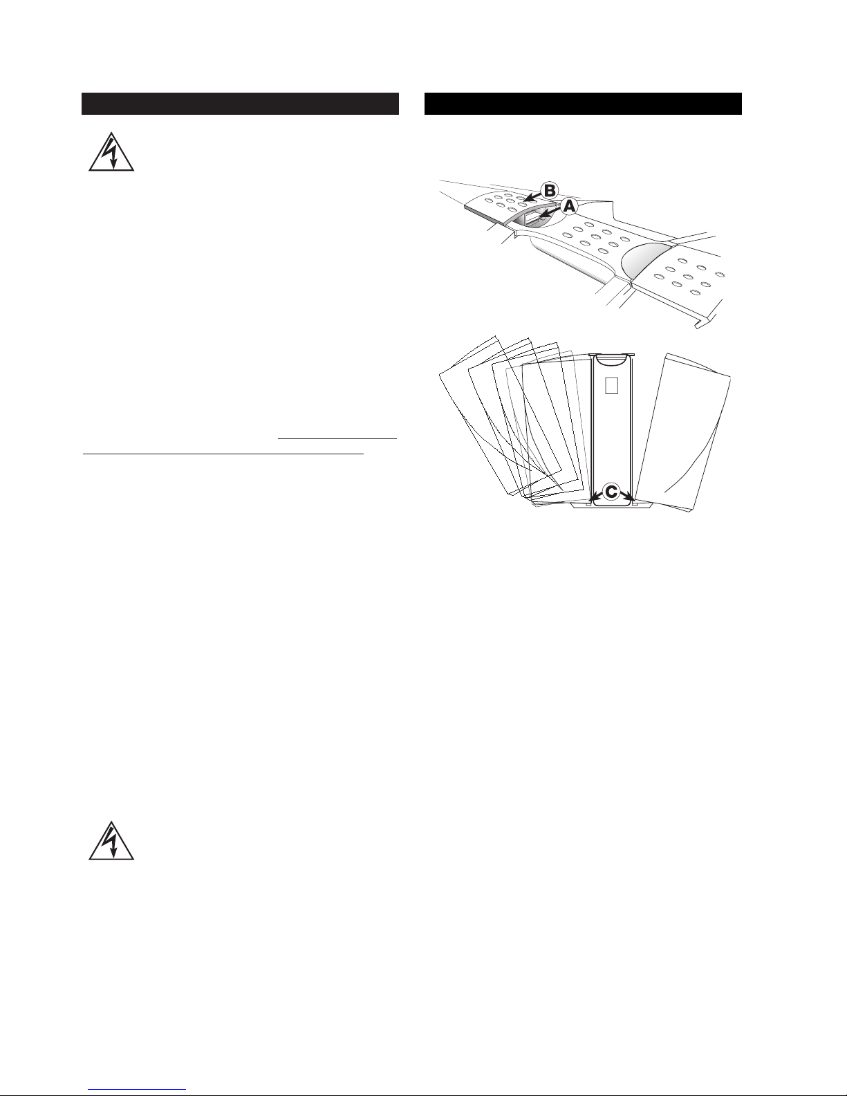
To open and close your Passport system, simply follow
these guidelines:
1. Place your finger tip under the safety latch and gently
lift. When the safety latch has disengaged, lift the main
latch to remove the speaker.
2. To replace, position the speaker on the tower foot and
bring the speaker in to close the engagement with the
tower and latch. Position the latch hook over the speaker
notch and close the latch. The safety latch will automatically engage.
Note: These parts are precision engineered and no force
is needed to secure them. Careful alignment of parts will
ensure easy operation.
TRANSPORTATION LATCHES
5
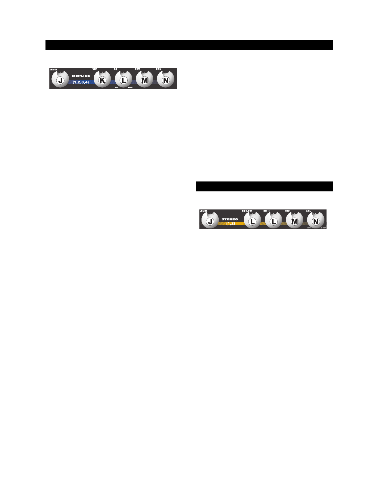
CHANNNELS 1 - 4
J. LEVEL – Adjusts the volume level of the individual
channel. Rotating the knob clockwise increases the
respective channel’s contribution to the “Main Out” mix,
while rotating it counterclockwise decreases the volume.
Adjust this control after the Passport’s master output level
volume has been set.
K. VIP (CHANNEL 1 ONLY) – The VIP or Vocal Input
Priority control adjusts the level at which the volume of all
other channels are automatically reduced in favor of the
source attached to the Mic/Line Input 1. This unique
feature permits a user to speak while other inputs (such as
background music) continue at temporarily reduced
levels. The VIP circuit is “pre-volume control” which means
it is effective regardless of level control setting of channel
one. Adjust this control while speaking into a microphone
on channel 1, with other program material input through
another channel. Depending on the duration and level of
the signal being input to Mic/Line 1 and the position of the
control, the VIP circuit will trigger a reduction in level of all
the other channels. The original levels will be automatically
restored when there is no signal present on channel 1. In
typical use, the circuit will return normal levels in about
4 seconds. With the level set at a higher or a stronger
signal, normal levels will be restored after approximately
6 seconds. The VIP circuit has an intentionally slow
release time which prevents interruptions when a speaker
pauses for thought or effect. Care should be taken to
avoid the VIP triggering on sound from the main speakers.
At high settings, the microphone may “hear” the main
system speakers and trigger a reduction in level. When
not using the VIP feature, be sure to turn the control
completely counterclockwise.
L. EQ – Adjusts the amount of frequency increase or
decrease in the channel. Rotating the knob
counterclockwise increases the bass or low frequency
response while simultaneously decreasing the treble or
high frequency response. Likewise, rotating the knob
clockwise increases the treble or high frequency response
while simultaneously decreasing the bass or low
frequency response. When the tone controls are set at
their notched or straight up position, the channel response
is “flat” with no frequencies increased or decreased. To
set the EQ, start with this control in the 12 o’clock
(notched) position. Simply turn the control until things
sound good!
M. REV/AUX – Adjusts the amount of signal sent to the
Reverb processor, and to the Rev/Aux output jack.
Reverb can be used to enhance the sound quality of any
performance where appropriate and desired. In the full left
position there is no level sent to the reverb processor or
Rev/Aux jack. Care should be taken to set the Reverb
return master control to a middle position or above, before
adjusting levels from the individual channels. When the
reverb/auxiliary mix is set, overall levels of reverb can be
adjusted at the master control.
Keep in mind that while Reverb or effects can enhance a
musical performance or presentation. Too much reverb
can make the same performance or presentation
unintelligible or “muffled”. Keep your audience in mind
when setting reverb levels.
N. PAN – The Pan control features a notched position
indicator and adjusts the perceived “position” of the mono
signal from the input within the stereo field created by the
two speaker cabinets. Full Left or Right rotation of this
control sends the signal to the that channel only, with no
signal sent to the other. The center position sends the
same amount of signal to both speakers.
J. STEREO INPUT LEVEL – Adjusts the volume level of
the stereo input channel. Rotating the knob clockwise
increases the stereo input channel’s contribution to the
“Main Out” mix, while rotating it counterclockwise
decreases the volume. Adjust this control after the
Passport’s master output level volume has been set.
L. EQ LOW – Adjusts the relative level of the low
frequency content for the stereo channel. Rotating the
knob counterclockwise decreases the bass or low frequency response. Likewise, rotating the knob clockwise
increases the bass or low frequency response.
L. EQ HI – Adjusts the relative level of the high frequency
content. Rotating the knob counterclockwise decreases
the treble or high frequency response. Likewise, rotating
the knob clockwise increases the treble or high frequency
response. When the EQ controls are set at their notched
or straight up position, the channel frequency response is
“flat” with no frequencies increased or decreased.
MONO MIC / LINE CONTROL FUNCTIONS
STEREO CONTROL FUNCTIONS

6
M. REV/AUX – Adjusts the amount of signal sent to the
internal Reverb processor, and to the Rev/Aux output
jack. In the full left position the control is effectively off.
Care should be taken to set the Reverb return master
control to a middle position or above, before adjusting
levels from the individual channels. When the
reverb/auxiliary mix is set, overall levels of reverb can be
adjusted at the master control.
N. BAL – The balance control features a notched position
indicator and adjusts the perceived “position” of the mono
signal from the input within the stereo field created by the
two speakers. Full Left or Right rotation of this control
sends the signal to the that channel only, with no signal
sent to the other. The center position sends the same
amount of signal to both speakers.
O & P. MASTER VOLUME LEVEL CONTROLS – The
Left and Right Master Volume Controls adjust the output
volume of the PD-250. The Master controls feature
notched position indicators. For the majority of
applications the Passport system has been balanced to
operate with these controls at their notched 12 o’clock
positions. In situations where more volume is required the
master controls can provide an additional 6 dB of gain
when turned to the right of the center position.
Set the system up in the normal manner and adjust levels
as necessary. Raise the master volume controls beyond
their 12 o’clock positions only after increasing the
individual channel level controls.
Passport’s internal amplifiers have on-board processing
designed to optimize the system’s performance when
used with the custom designed PD-250 speakers.
S. STEREO/ DUAL SELECTOR SWITCH – Allows the
PD-250’s power amps to be configured as stereo or
“dual-mono”. In the Stereo mode, the system operates as
a traditional stereo power mixer/ amplifier. In the Dual
mode, the channel level controls set the level for the Main
mix (LEFT master volume control). The Rev/Aux controls
set the individual channel levels for the Monitor (RIGHT
master volume control).
When the Dual mode position is selected with the switch,
the Pan and Balance controls become inoperative (you
have selected a mono setting for the output). Additionally,
the internal reverb is only sent to the MAIN speaker
output. Reverb is not available to the MONITOR speaker
output. The reverb level sends for the MAIN mix are also
controlled from the channel REV/AUX channel controls.
The overall reverb level to the MAIN mix is controlled by
the Reverb Master Control.
Q. MASTER REVERB – Adjusts the amount of reverb
signal level sent to the mix or output. Rotating the knob
clockwise increases the reverb signal sent to the main
mix. When the knob is in its full counterclockwise position,
there is no reverb heard in the mix.
R. SYSTEM EQ – Adjusts the overall amount of frequency
increase or decrease on the Passport. Rotating the knob
counterclockwise increases the bass frequency response
while simultaneously decreasing the high frequency
response. Likewise, rotating the knob clockwise increases
the high frequency response while simultaneously
decreasing the bass frequency response. When the
system EQ control is set at its notched or straight up
position, the channel response is “flat” with no
frequencies increased or decreased. To set the System
EQ, start with this control in the 12 o’clock (flat) position.
Simply turn the control until things sound good!
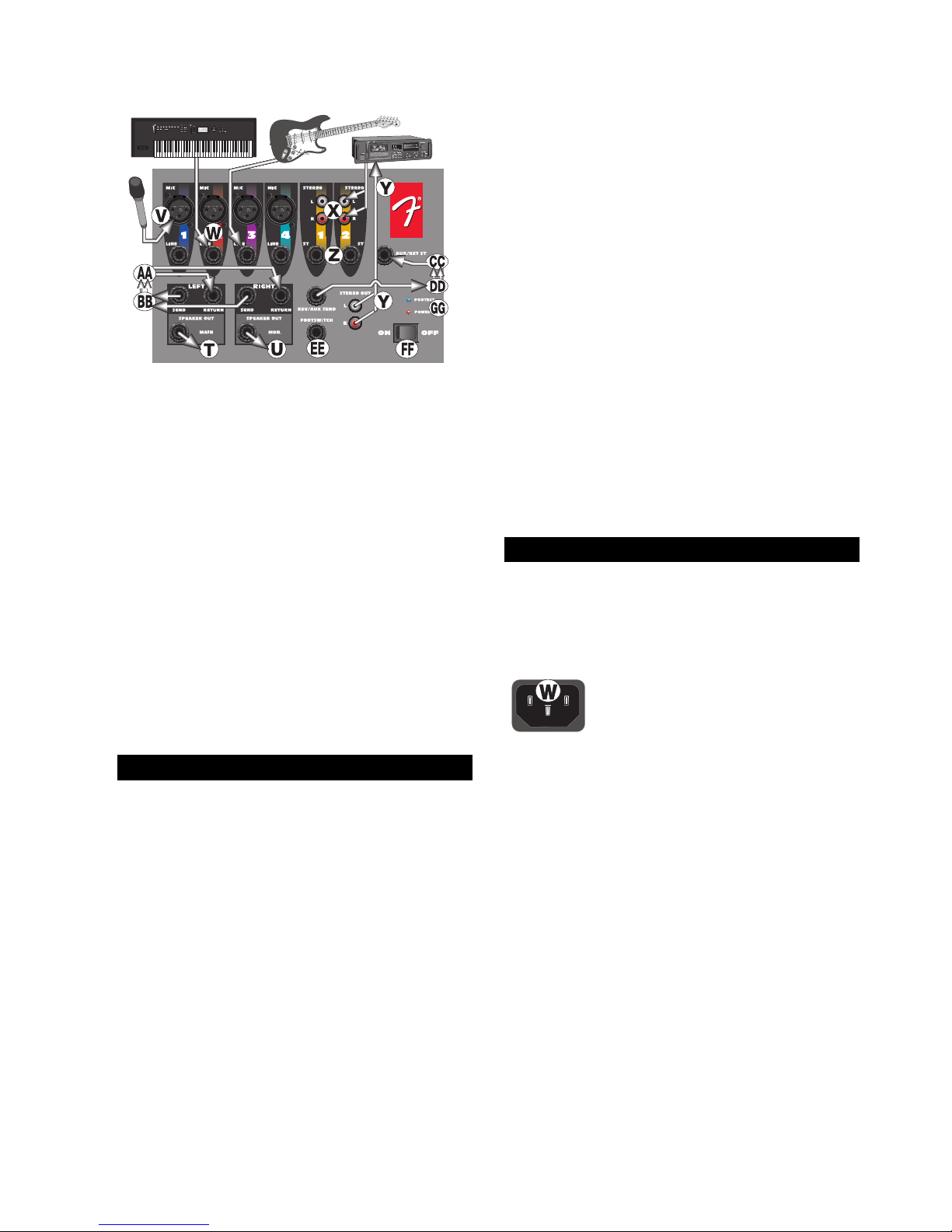
You will notice that the input jacks and channel
controls are color coded. This is done to easily
identify which set of controls is associated with which
input connections.
V. MIC INPUT JACK
– Plug your micro-
phone in here. This three
pin XLR balanced female
input connector is intended
for input signals from low
impedance microphones.
W. LINE INPUT JACK – Plug your instrument in here.
This 1/4 inch balanced input jack suited for use with items
having a line level output such as high impedance
microphones, keyboards, drum machines, outboard
effects, etc. It accepts both balanced and unbalanced
cables.
MASTER CONTROL FUNCTIONS
MIC / LINE / STEREO INPUTS
7
X & Z. STEREO INPUTS – Stereo phono (RCA) input
jacks and 1/4” TRS jacks (wired for Tip=Left, Ring=Right
and Sleeve=Ground, the standard format of commercially
available cables) designed for use with a tape player, CD
player, or any other stereo source. Use these jacks for
connecting the output of a computer sound card or other
similar device to your Passport. Adapters that convert an
1/8” male plug to RCA male phono plugs are readily
available at electronics stores. Note: These connectors
are set at a constant “line level”.
Y. STEREO OUT – The Tape Out RCA jacks provide a
mix output that is independent of the Master Level
Controls. Connect these to the inputs of a recording
device, such as a cassette or DAT recorder, to record
your event. Changes made during the performance, to the
input level controls, channel EQ, and reverb controls will
be heard in the Tape Out mix. Changes made to the
master level controls will not effect the level of the
recording. Adjust recording levels according to the
instructions on your recording device.
DD. REV/ AUX SEND – Plug your external effects signal
processor in here. Although the Passport is already
equipped with on-board digital reverb, an external effects
signal processor can be incorporated into the Passport’s
signal flow. This 1/4 inch output jack is designed to feed
the Passport’s effects bus signal to an external signal
processing device, such as a digital delay or a chorus.
CC. AUX RETURN – Plug your external effects signal
processor’s output signal in here. This 1/4 inch input
stereo jack is designed to accept signals from an external
processing device, such as a digital delay or a chorus unit.
This input can also be used as a stereo input with the
volume controlled at the master volume knobs.
EE. FOOT SWITCH – The Footswitch connector allows
the internal reverb return to be muted, or shut off, through
the use of a simple foot operated switch (Fender part
number 099-4052-000). The footswitch should be wired
to connect the tip to the sleeve to turn the reverb off, and
requires a standard speaker or instrument cable.
AA & BB. – AMPLIFIER SEND/ RETURN JACKS – Each
channel of the amplifier has a Send and Return jack.
These jacks provide a point to patch in an equalizer, or
other processor into the sound system. The signal at the
send jack is located after the mixer section and before the
power amplifier. The send jack should be connected to
the input of the external device. The return jack is a patch
point that enters into the power amplifiers. The return jack
should be connected to the output of the external device.
T & U. SPEAKER OUTPUTS – These are speaker level
(powered) output jacks designed to feed each of your
Passport speaker enclosures. Use the enclosed cables (or
other speaker cable) to connect the Passport’s speakers
to the power tower.
FF. POWER SWITCH – Turns the AC power ON and
OFF. When the switch is in the OFF position, your Passport is completely shut down.
AC CONNECTOR/ LINE CORD – The Passport is
equipped with a grounding type IEC supply cord to
reduce the possibility of shock hazard. Be sure to connect
it to a grounded AC receptacle. DO NOT ALTER THE AC
PLUG.
The power mains (AC) fuse and fuse holder
are under the IEC (power cord) socket.
Replacement fuses must be of the same
rating (6.3A, 250V) and size as originally
equipped. To replace a blown fuse, remove the IEC power cord. Pull out the fuse holder and
find the spare fuse inside.
Your Passport system is capable of running on battery
power. The off-white plastic connector on the rear of your
Passport is the DC power input connector for connecting
the Passport DC-DC converter. The converter is then
connected to a battery. Available accessories include the
Passport DC-DC converter (Fender part number
069-1002-000) and 12 volt battery pack (Fender part
number 069-9003-000).
AUX AND FOOTSWITCH JACKS
REAR PANEL

8
A small storage compartment can be found on the rear of
the Passport tower. To access this compartment, simply
lift the latch and pull open the storage door. This
compartment is ideal for storing cables, microphones or
other items when you are transporting your Passport.
On the back panel of the storage compartment you will
see a narrow metal strip with a screw on either end. This
is the protective cover for the wireless adapter terminal.
Custom wireless systems are available for your Passport.
The receiver for the wireless system installs in the storage
compartment.
Before turning on the Power, read and heed the safety
warnings on page 2.
It is wise to establish a routine for connecting and
powering up your sound system. Provided you have a
properly grounded AC outlet or outlet strip with sufficient
power handling capacity, plug all sound system
equipment into the same outlet or strip. This will enhance
system safety and performance. Take care that the AC
circuit is capable of handling the peak power demands of
your system. Consult the product handbooks or a
qualified electrician if in doubt.
When setting up, be sure to follow these simple set-up
guidelines:
1. First, turn all channel Level, VIP (channel 1 ONLY) and
Rev/Aux controls to their full counterclockwise (OFF)
positions. Next, place all EQ, Pan and Master controls at
12 o’clock in their center notched positions. Be sure to
set the appropriate input (mic/line switch position) for the
source you are setting up.
2. Next, connect each speaker cable to the appropriate
Left & Right Speaker outputs on the rear tower and on
each speaker front panel with the enclosed cables.
3. Connect all sources such as microphones, tape decks,
keyboards etc., into the appropriate inputs.
4. Finally, check the local voltage and set the voltage
selector switch located adjacent to the power input
socket on the rear of the mixer/amplifier to the appropriate
operating range. (See Safety Precautions on page 2.) Plug
the power cable into the IEC (power cord) socket on the
rear of the Passport Tower and connect the other end to
a properly grounded 3 wire AC power outlet.
POWERING UP
Turn the Power Switch to the ON position. The Power
LED will illuminate green and the system will turn on. If
other powered equipment is to be attached to the system,
it is always advisable to turn on your Passport last. In this
way any transient spikes and thumps caused by other
equipment will not be amplified and sent to your system
speakers. For the same reasons it is advisable to turn off
your Passport system first before turning off the attached
equipment.
Should the Power LED not illuminate when the rear panel
power switch is operated, check your power connections
and retry. Should the Power LED still fail to illuminate after
you have confirmed the power connections, disconnect
all cables and check the Passport fuses. Be sure to
replace any blown fuses with fuses of the correct value.
Reconnect the power and speaker cables and turn the
rear panel power switch on.
Re-set the system by turning on the power switch. If the
Power LED illuminates red, the system is indicating a
thermal protect mode or cooling problem. Be sure to
check the air inlet filter at the base of the unit by removing
it and making sure it is clear of debris.
Turn power off and wait for a few minutes allowing heat to
dissipate and the Passport to reset itself. If after doing so
the Power LED continues to glow red this indicates a fault
with your system and you should consult an authorized
Fender service center.
If no audio is present in one of the speakers, check to see
if your control settings are correct. Next, unplug the cable
from your working speaker and reconnect it to the other
speaker. If the second speaker now works, this indicates
that the first cable is bad, and should be repaired or
replaced.
SET-UP SYSTEM VOLUME AND LEVELS
To set system volume and operating levels, be sure to
follow these simple set-up guidelines:
1. First, slowly raise the large Left and Right Master
volume controls to their 12 o’clock notched positions.
2. Use a microphone (or other source) in the same
position as it will be used on stage and in the manner in
which it will be used for the event. Slowly bring up the
appropriate channel input level control listening for the
onset of feedback or howling or until the required level is
reached. Have a helper “walk” the audience area to make
sure coverage and levels are sufficient for your needs. The
system’s overall volume can be raised simply by rotating
the Left and Right Master volume controls to the desired
level.
REAR STORAGE COMPARTMENT
SET-UP AND CONNECTIONS

9
3. Consider the application and needs of the
event and set the System EQ control as
appropriate. This is best achieved by playing
recorded material of the same type as your
show program, or by having an assistant speak
into the microphone while you listen in the
audience area.
For public address (spoken voice), it is advisable
to rotate the System EQ control clockwise to
enhance the mid and high frequencies, and limit
the low frequency content. For large outdoor
spaces this will also give the maximum
headroom and output capability. Carefully
consider the individual event’s needs and set
your control for the maximum effect.
POWER TOWER™
In setting up the system, the Passport Mixing
console should ideally be placed where system
performance can be evaluated by the operator.
If no ongoing adjustments will be necessary, the
mixer may be placed conveniently and where
the cable lengths allow.
Take care to place the Power Tower where the
cables will not trip anyone. All cables should be
carefully secured.
The storage compartment in the rear of the
Tower can hold cables, microphones and other
system parts. To open simply slide the catch
upwards and pull open.
The mains (AC) fuse holder is under the IEC
(power cord) socket on the right rear of the
Tower. To change a fuse, remove the IEC plug
and, using an appropriate tool pull out the fuse
holder. Note there is a spare fuse in the fuse
holder; the Passport utilizes a T6.3A 250V fuse.
Only replace fuses with one of an identical value
and size.
The Passport System is weather resistant in its
packed- transport mode. However, when
operating outdoors, take care to fully protect the
Power Tower in the event of exposure to rain.
Remember to allow free air flow through the
front air inlet located at the bottom of the
front panel on the Passport power tower.
SPECIFICATIONS
Part Number
069-2001-0X3
Frequency Response
20 Hz to 40 kHz ± 1 dB (at send output)
30 Hz to 30 kHz ± 1 dB (at speaker output,
with processor threshold exceeded)
Distortion
< 0.05%, 20 Hz to 20 kHz, 1 dB below rated output
System Signal to Noise Ratio
> 80 dB @ 1 w, “A” WTD
Power Output
125 W/ch continuous average power, 8ohm,
both channels driven with THD < 1%
Input Impedance (Channels 1-2-3 XLR and 1/4”)
“Mic” switch position: 2 k ohm
“Line” switch position: 66 k ohm
Input Impedance (Phono and Stereo Channel 1/4”)
78 k ohm
Max. Input Level
Mic: -7 dBu
Line: 30 dBu
Stereo: 26 dBu
Return Input Impedance
47 k ohm
Fuse type
T6.3A, 250 V
Passport System
Width: 840 mm (33.7 in.)
Height: 615 mm (24.2 in.)
Depth: 300 mm (11.8 in.)
Weight: 24 kgs (53 lbs)
Speakers
Width: 340 mm (13.4 in.)
Height: 610 mm (24.2 in.)
Depth: 300 mm (11.8 in.)
Weight: 6.8 kgs (15 lbs)
Power Tower
Width 185 mm (7.3 in.)
Height 615 mm (24.2 in.)
Depth 300 mm (11.8 in.)
Weight 10.5 kgs (23 lbs)
Tower Footprint
350 x 300 mm (13.8 x 11.8 in.)
Microphone
Dynamic Cardioid, balanced
Microphone Cable
XL -Male to XL-Female, 6 m (20 feet)
Speaker Cables
1/4 in. to 1/4 in., 9 m (30 feet)
0 dBu is referenced to 0.775 volts rms


Thank you for selecting the Fender Passport Wireless System. Before installing or operating this system please read this instruction manual
thoroughly and familiarize yourself with the system components and correct operating procedures.
What is covered in this manual
Descriptions, installation and usage for the Passport Wireless Handheld System, Passport Wireless Executive System and Passport Docking Receiver
are covered in this manual.
Overview
The Fender Passport Wireless Systems are unique, extremely simple, yet effective systems, which provide high quality, reliable wireless microphone
operation.
The Fender Passport Wireless System combines high technology design with the latest construction methods and high quality components for
superior performance in all applications. Fender’s fifty-plus years of experience in building professional instruments gives us a clear understanding of
the importance of reliable and consistent operation show after show. Your choice of this high quality system will result in years of reliable service.
Design Notes
In keeping with the principles of ease of use and reliability, the Passport Wireless System accessories for the Passport family of products is designed
to require little or no additional operations or adjustments before each use. In fact these wireless systems require less set-up than even the normal
wired microphone! Once installed, the only requirement of the operator is to make sure the microphone/ transmitter is fitted with a fresh battery.
Systems
The Passport Wireless Handheld System
Contains a handheld wireless microphone (transmitter) and custom-designed docking receiver.
The Passport Wireless Executive System
Contains a belt-pack transmitter, a lavalier microphone, a headset microphone, an instrument cable, and a custom designed docking receiver.
An additional transmitter may be purchased separately to compliment either system. Make sure to order any additional transmitters in the correct
frequency. Consult your Fender dealer for details and options.
Wireless Components
Transmitters
Handheld Microphone (Handheld System)
The Fender Handheld microphone and transmitter is a high quality microphone combined in a compact and lightweight package. The microphone
element is a professional, electret-condenser type with very low handling noise, excellent frequency response and cardioid pattern characteristics.
The Handheld microphone uses a 9v battery in the lower battery housing. To replace, simply remove the bottom section by twisting counter
clockwise. Note the plus and minus signs and make sure to insert the battery in the correct direction and orientation. Take care to not cross threads in
the housing when replacing.
An ON/OFF switch is the only control on the unit. When the switch is moved to the ON position the LED indicator should momentarily flash red. If
the LED stays on, the battery level is too low for normal operation.

Belt Pack Transmitter Unit (Executive System)
The Belt Pack transmitter has a 4-pin input connector for use with the interchangeable microphones and instrument cable. The microphone and
instrument cables have a miniature jack plug. These have threaded collars to assure secure attachment to the transmitter. When attaching an input
source, make sure to insert its jack plug, then turn clockwise to lock into place
Located on the front panel is an on/off switch and battery low indicator. The Power LED will flash briefly upon turn-on when the battery is in good
condition. When the LED is on continuously, the battery level is too low for normal operation.
On the side of the transmitter are level controls. A level switch provides two input level settings – GT (electric guitar) and MT (microphone). When
in the MT position, the Gain control adjusts the input gain for the microphone. The gain is fixed (and the gain control is inoperative) when in the GT
position.
The transmitter uses one 9-volt alkaline battery, with the battery compartment accessed on the lower right side. Take care to place the battery into its
housing in the correct direction. Look carefully at the battery and identify the plus or positive terminal.
Lavalier Microphone
For general purpose public speaking a lavalier microphone, sometimes known as a lapel microphone, can be very effective. One advantage of this type
of microphone is its relative invisibility. The microphone element is an electret-condenser type.
Headset Microphone
This microphone is essentially of the same type as the lavalier microphone. Fender’s design features a number of advantages for entertainment and
presentation applications. The Fender headset system can be worn securely and comfortably even when used by physically active performers or
instructors. It is designed to go underneath and around the hairline at the back of the neck and fix lightly but securely to the ears of the user.
The headset assembly has a number of adjustments. The neckband is adjustable for size and fit. The pivot arm tension and length can be adjusted. Do
not adjust the arm without loosening the screws slightly.
Instrument Cable
The instrument cable allows virtually noise-free, high quality wireless transmission of instruments or line level sources. The cable simply plugs
directly into the source instrument and the transmitter.
Receiver
Custom Docking Receiver
The wireless receiver is built into the “docking” unit that mounts inside Passport’s storage compartment. All power, audio and antenna connections
are built into the docking receiver.
When you install the docking receiver, audio connections are automatically made to input channel one of the Passport. In other words, input channel
one is now dedicated to the Wireless System. The Wireless Systems come with “blanking plugs” (install in the XLR and ¼” jacks for channel one)
intended as a reminder that this input is in use.
Docking Receiver Indicators
The Passport docking receiver receives power from the Passport. When the Passport main power switch is on (*), the red “Power” LED on the
Wireless docking receiver will illuminate.
* For DC operation only: The Passport front panel ON/OFF switch is not operational when used with a DC-DC converter. The Passport is turned on
and off via the DC Converter On/Off switch. The Wireless Module power LED (red) will illuminate as normal.
The “Signal Present” Green LED on the docking receiver will illuminate when the transmitter is turned “on”- showing the receiver is “seeing” a signal
from your transmitter.
Tone Key
With the Passport Wireless System, the transmitter and receiver are locked to a specific tone key frequency that is carried “invisibly” with the signal
from the transmitter. If the receiver loses this tone key, it soft-mutes the output of the receiver. In this way, should for example, the battery run low
in your transmitter, and its transmission is interrupted, no annoying noises or spurious signals will be fed to the system.

A second advantage to this tone key system is that the transmitter can be turned on and off without having to turn off the receiver – or mute its
channel on the Passport.

Setting Up
Unpacking
Your Passport Wireless System (or accessory) was packed with care at the factory. The shipping carton was designed to protect it during initial
shipment. Please retain this carton in the unlikely event that you need to return your Passport Wireless for servicing.
Remove the Docking Receiver and the transmitter (either Handheld or Belt pack) from their respective packaging and check that nothing is missing
and/ or damaged from shipping.
Confirm that the Receiver and Transmitter are of the same frequency. If you find the pieces are NOT the same frequency please contact the dealer
where you purchased the item(s).
Pre-Installation
The Passport Wireless Systems and accessories are custom designed to work with “wireless ready” Passport Sound Systems. “Wireless Ready”
Passport Sound Systems have a “docking connector” in their rear storage compartment. This is very easy to identify as “non-wireless ready”
Passports have nothing in their storage compartments.
If you have purchased a wireless system and find you’re Passport does not have the “wireless ready” feature, please contact your Authorized Fender
Pro Audio dealer or our Customer Service department for information and availability of a “wireless retro-fit kit”. This kit will need to be installed by
an Authorized Fender Pro Audio Service Center.
Safety Precautions
Warning: To avoid the risk of shock or fire, do not expose this unit to moisture. Do not attempt to disassemble or alter any circuitry. There are no
user-serviceable parts inside. Refer all servicing to an Authorized Fender Pro Audio qualified service personnel.
Installation
Custom Docking Receiver
Disconnect power cable!
Identify the Docking Receiver module and familiarize yourself with the unit, noting the two locking screws and multi-pin connector.
Place your Passport power tower facedown on a level and stable surface. Open the storage compartment door and identify the docking connector on
the rear wall of the storage compartment.
Locate the two small screws attaching the protective cover over the docking connector. Loosen these screws just enough to allow the cover to be
removed from the connector. Gently re-tighten the two screws.
Holding the Docking Receiver with the logo in an upright position, place the male, multi-pin connector into engagement with the female connector on
the Passport storage compartment rear wall. When properly aligned, gently (but firmly) push the unit until it engages fully. Using the two screws on
the sides of the module, attach the module to the Passport. Do not over-tighten.
Identify the two “blanking plugs” and install these into the channel one, XLR and 1/4” connectors.
Transmitter (Handheld and belt pack)
Identify the battery compartment on the transmitter and install a fresh 9V Alkaline Battery. If using the belt pack transmitter, select a microphone or
cable to use and attach to the transmitter.
You have now completed the installation, and all that remains is to confirm the proper operation of your system.

Operation
Once installed, the wireless system is automatically input to channel one of the Passport. The Wireless Systems come with “blanking plugs” (install
in the XLR and ¼” jacks for channel one) intended as a reminder that this input is in use.
Set-up your Passport system as you would for normal use. Confirm operation of the system with a CD or wired microphone source.
Make sure the input one level control is turned to its minimum setting.
(fully counter-clockwise).
Turn the Passport main power on, open the storage compartment and confirm that the Red “Power” LED on the wireless-docking receiver is
illuminated.
Turn on the handheld or belt pack transmitter. The Green LED on the docking receiver will illuminate - showing the receiver is “seeing” a radio
frequency carrier signal from your transmitter.
While using the microphone at a normal level, slowly bring up the input level control for channel one. You should be hearing yourself in a clear and
natural tone much the same as the wired microphone with which you checked the system. Adjust the EQ control to your requirements.
Note: The front panel Mic/Line switch does not effect the level sensitivity for Wireless operation. Fender has “normalized” the docking receiver’s
output to the system-input section. No additional adjustments are required of the operator.
Congratulations you have successfully set-up the wireless system!
From this point onwards, you should need only to change batteries in your transmitter for continued operation.
If your wireless system fails to work properly, consult your authorized Fender Service Center.
Frequencies
Passport Wireless Systems are available in a number of frequencies. The last three digits of the part number indicate the frequency of your system (or
component). If ordering an additional component for your existing system, be sure to order the component with the same frequency. The frequencies
and three digit numbers are identical for all Passport Wireless Accessories.
The most popular wireless frequencies are the Travel Frequencies. As their name implies, travel frequencies are “open channels” in all areas of North
America.
Wireless systems broadcast in the same way as radio and television stations broadcast (only a much weaker signal). It is easy to see why a wireless
system could pick up interference from a local television station broadcasting on the same frequency. You will notice that all frequencies except
“travel” frequencies have television channels associated with them. When selecting a wireless frequency, choose one that is a television channel NOT
broadcast in your area (or the area where you will most typically use your Passport). Cable channels should not affect the performance of your
wireless.
The following list shows the available frequencies and their associated part numbers for Passport Wireless Systems.
Part Number: Channel Frequency
069-xxxx-001 Travel A 169.505 MHz
069-xxxx-002 Travel B 171.905 MHz
069-xxxx-004 Channel 7 174.8 MHz
069-xxxx-005 Channel 11 202.4 MHz
069-xxxx-006 Channel 12 206.4 MHz
069-xxxx-007 Channel 10 195.4 MHz
069-xxxx-008 Channel 13 208.2 MHz

Wireless System Specifications
Carrier VHF 160-250MHz specific freq. Only
Oscillation Mode Quartz-Controlled
Channel Single
Receiving Mode Non-Diversity
Dynamic Range >100dB
Squelch Tone Key squelch controlled circuitry
S/N Ratio >100dB
T.H.D. < 0.5%
Freq. Response 50Hz-18kHz +/-3dB
Product Specifications are subject to change without notice.
Please visit www.fenderaudio.com and www.fender.com
A Product of:
Fender Musical Instruments Corp.
Corona, CA 91720 USA
 Loading...