

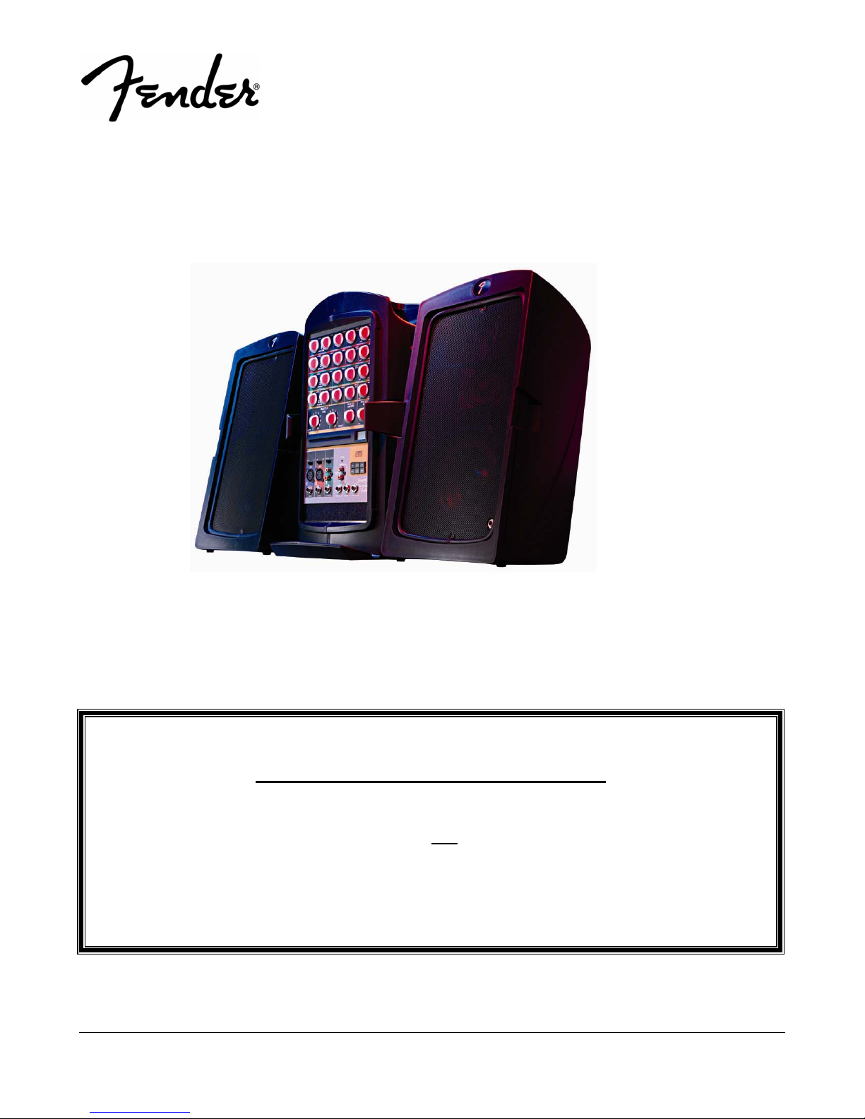
PASSPORT® PD-150 PLUS
(This is the model name for warranty claims)
SERVICE MANUAL
p/n 069-3005-000
WARRANTY SERVICE PROCEDURES
Warranty field service of the Passport PD-150 Plus will be limited to replacement of
defective PCB Assemblies and all other parts not
Warranty repairs can of course be to the component level at the Service Center’s
discretion. For non-warranty component level repairs all parts listed as “REF” in the Parts
List must be sourced from suppliers other than FMIC.
Fender Musical Instruments Corporation, 8860 East Chaparral Road Suite 100 Scottsdale, AZ 85250
ATTENTION:
marked as “REF” in the Parts List. Non-
Issued: October, 2006

2
PASSPORT
(This is the model name for warranty claims)
February, 2007
IMPORTANT NOTICE
®
PD-150 PLUS
• Copyright © 2007 FMIC. All rights reserved. All
information contained herein is CONFIDENTIAL
and PROPRIETARY and is the property of
Fender® Musical Instruments Corporation. It is
not to be sold or assigned to another party and is
disclosed solely for use by Fender Authorized
Service Centers for purposes of product service
and maintenance. All information is not to be disclosed to others without the expressed permission
of Fender® Musical Instruments Corporation. All
PARTS LIST CODES
The description codes used in the itemized Parts Lists are defined below:
CAPACITOR
CAP AE = Aluminum Electrolytic
CAP CA = Ceramic Axial
CAP CD = Ceramic Disk
CAP CR = Ceramic Radial
CAP MPF = Metalized Polyester Film
CAP MY = Mylar
CAP PFF = Polyester Film/Foil
RESISTOR
RES CC = Carbon Comp
RES CF = Carbon Film
RES FP = Flame Proof
RES MF = Metal Film
RES MOX = Metal Oxide
RES WW = Wire Wound
CODES
CODES
specifications are subject to change without notice. This information and any copies produced
electronically or otherwise must be surrendered
upon demand of Fender® Musical Instruments
Corporation.
• Parts marked with two asterisks (
required use of that specific part. This is necessary for RELIABILITY and SAFETY requirements.
DO NOT USE A SUBSTITUTE!
HARDWARE
BLX = Black Oxide
CR = Chrome Plated
HWH = Hex Washer Head
M = Machine Screw
NI = Nickel Plated
OHP = Oval Head Phillips
PB = Particle Board
PHP = Pan Head Phillips
PHPS = Pan Head Phillips Sems
SMA = Sheet Metal "A" Point
SMB = Sheet Metal "B" Point
SS = Stainless Steel
TF = Thread Forming
ZI = Zinc Plated
CODES
**) indicate the

®
PASSPORT
(This is the model name for warranty claims)
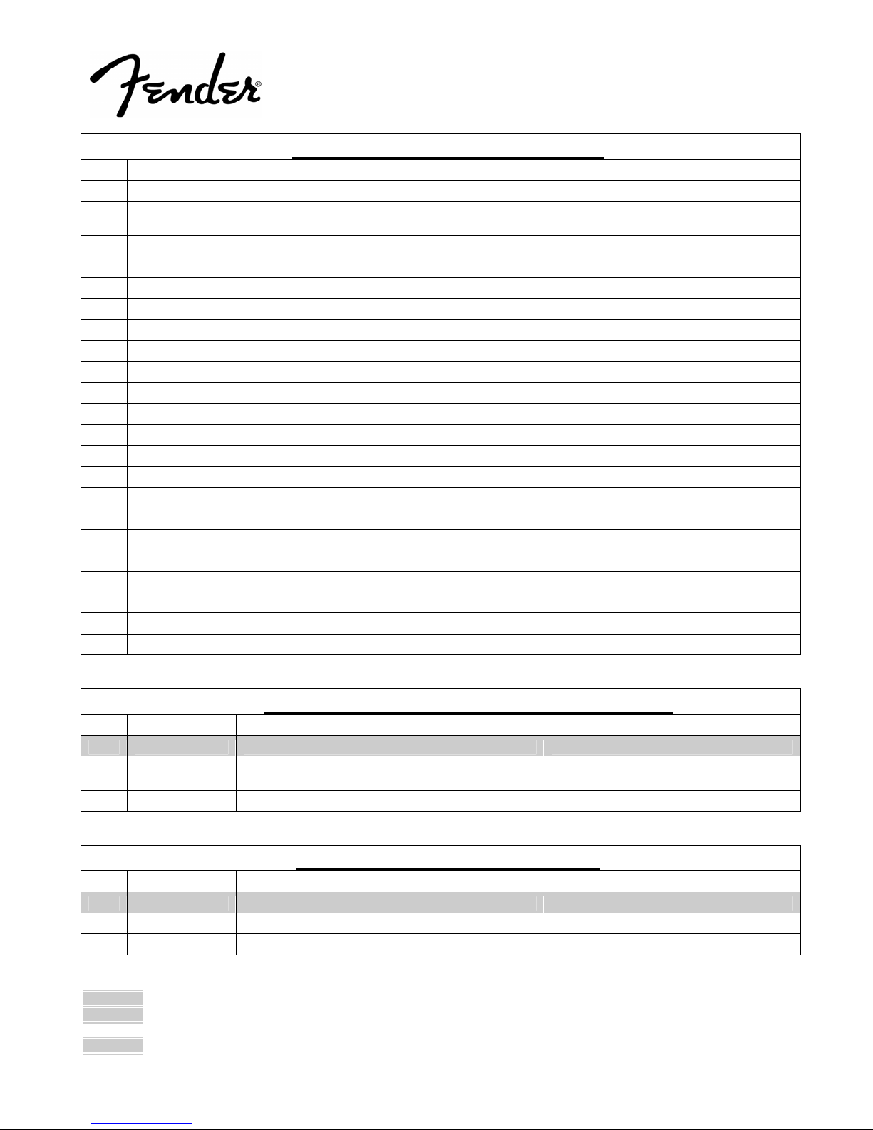
SPECIFICATIONS
Model Name: PASSPORT PD-150 PLUS
Release Number: PR688
Part Number: (120V, 60Hz) US: 069-3005-000
(120V, 60 Hz) DS: 069-3005-900
(240V, 50 Hz) AUS: 069-3005-930
(230V, 50 Hz) UK: 069-3005-940
(230V, 50 Hz) EUR: 069-3005-960
(100V, 50 Hz) JPN: 069-3005-970
Frequency Response: 50 Hz to 20 kHz ± 1 dB (at speaker output)
30 Hz to 20 kHz ± 1 dB (at send output)
Distortion: < 0.5%, 20 Hz to 20 kHz (at speaker output)
< 0.1%, 20 Hz to 20 kHz (at send output)
Signal to Noise Ratio: > 90 dB, “A” WTD
Power Output: 150W (75W/ch @ 8
Input Impedance:
(Channels 1-2 XLR and 1/4”) “Mic” switch position: 2 k
“Line” switch position: 66 k
(Phono and Stereo Channel 1/4”) 78 k
Max. Input Level: Mic: -11 dBu
Line: 20 dBu
Stereo: 26 dBu
Return Input Impedance: 47k
Fuse type: T3.15AL, 250V
Passport System: Width: 610 mm (24 in.)
Height: 541 mm (18 in.)
Depth: 254 mm (10 in.)
Weight: 14.97 kgs (33 lbs)
Speakers: Width: 245 mm (9.65 in.)
Height: 439 mm (17.5 in.)
Depth: 241 mm (9.5 in.)
Weight: 4.08 kgs (9.0 lbs)
Power Tower: Width: 245 mm (9.65 in.)
Height: 451 mm (18 in.)
Depth: 178 mm (7 in.)
Weight: 6.80 kgs (15.00 lbs)
Tower Footprint: 241 x 298 mm (9.5 x 11.75 in.)
Microphone: Dynamic Cardioid, balanced
Microphone Cable: XL -Male to XL-Female, 6 m (20 feet)
Speaker Cables: 1/4 in. to 1/4 in., 9 m (27 feet)
Ω
Ω
Ω per channel)
Ω
Ω
3
PD-150 PLUS
0 dBu is referenced to 0.775 volts rms
Product specifications are subject to change without notice

SERVICE NOTES
The following describes the procedure to dismantle
the PD-150+ Cabinets.
STEP A: PD-150+ CABINET
A1. Unscrew two M4 machine screws on each of
the left and right hatches on either side of the
unit (8 total).
A2. Unscrew two M3 pan-head machine screws
on the handle cover and detach it.
A3. Place the unit upside down. Unscrew eight M4
self-tapping screws off the foot standers.
A4. Detach the foot standers. There are six M3
self-tapping screws in the middle portion.
A5. Unscrew three M3 self-tapping screws located
on the right-hand-side.
A6. Place the unit in the normal position.
A7. Locate the four M3 and two M4 self-tapping
screws on the top and unscrew them.
A8. Separate the left and right cabinets.
A9. Locate the UHF and VHF antennas on the
right and left cabinets respectively.
A10. De-solder both antennas.
A11. Unscrew three M3 self-tapping screws on left
and right side panels (6 total) of the tower
metal assembly.
A12. Unscrew eight M2.6 and six (three on top of
front panel, three on top of rear panel) M3
self-tapping screws.
A13. Detach the left and right metal side panels.
A14. Detach the 8-pin antenna connector.
A15. Detach the top metal cover.
A16. Unscrew seven outer M3 self-tapping screws
on the rear panel.
A17. Detach all connectors.
A18. The procedure is completed.
STEP B: PD150+ MIXER PCB
B1. Detach 24 knobs and their nuts.
B2. Detach the Reverb PCB assembly.
PASSPORT
(This is the model name for warranty claims)
B3. Unscrew nine M3 machine screws from the
mixer PCB assembly.
B4. Detach all connectors.
B5. The procedure is completed.
STEP C: PD150+ DSP REVERB PCB
C1. Detach all connectors.
C2. The procedure is completed.
STEP D: PD150+ INPUT PCB
D1. Unscrew six screws and nuts from the front
panel.
D2. Detach all connectors.
D3. The procedure is completed.
STEP E: PD150+ DAMP PCB
E1. Unscrew four screws from the PD150+ DAMP
PCB.
E2. De-solder four wires connecting to Output
PCB assembly.
E3. The procedure is completed.
STEP F: PD150+ SMPS PCB
F1. Unscrew three screws from the front panel.
F2. Unscrew two screws at the back of the CD
mechanism.
F3. Detach all wiring and connectors.
F4. Unscrew six screws from the top cabinet of
the SMPS.
F5. Unscrew three screws from the bottom cabi-
nets of the SMPS.
F6. Detach the spacer from the wiring of the
SMPS.
F7. Unscrew the earthing M4 nut.
F8. Detach the mains connector from the AC inlet.
F9. Unscrew five screws from the SMPS PCB as-
sembly
F10. The procedure is completed.
PD-150 PLUS
®
4

STEP G: PD150+ LCD KEY PCB
G1. Unscrew six screws from the LCD KEY PCB.
G2. Detach all connectors.
G3. The procedure is completed.
STEP H: PD150+ CD SERVO PCB
H1. First complete STEP D.
H2. Unscrew three screws from the SMPS at the
front panel.
H3. Unscrew two screws from the CD mechanism
at the back.
PASSPORT
(This is the model name for warranty claims)
H4. Detach all wiring from the SMPS cabinet.
H5. Unscrew four M2 machine screws from the
CD SERVO PCB assembly
H6. Detach/De-solder all wiring and connectors
from the CD SERVO PCB assembly.
H7. The procedure is completed.
STEP I: Output Jack PCB
I1. Remove the two M9 nuts and washers on the
Output Jack PCB assembly.
PD-150 PLUS
®
5

PCB EXCHANGE POLICY
Parts marked with a single asterisk (
Lists are not field replaceable. If a failure due to
one of these components is detected, please
*) in the Part
CIRCUIT DESCRIPTION
This section provides concise information about new
or unusual circuitry designs incorporated into this
amplifier model. The purpose is to aid the service
technician by providing insight into the design areas
most likely to become obstacles in troubleshooting.
Information is focused for its effective use while
maintaining the security of Fender® proprietary
information wherever possible.
The PD-150+ consists of the following modules:
1. The SMPS PCB module
2. The CD servo PCB module (common with PD250+)
3. LCD Key PCB module
4. The input PCB module
5. The mixer PCB module
6. The class-D amplifier PCB module
7. The DSP Reverb PCB module (common with
PD-250+)
The SMPS PCB Module
The SMPS PCB module accepts AC mains voltage
from 90Vr.m.s. ~ 264Vr.m.s. and provides the following output voltages to power the PD-150+ for
various functions:
1. +42.5V DC for the class-D amplifier PCB assembly
2. +15/-15VDC for the input PCB assembly
3. +12VDC for the fan
4. +8VDC for the wireless microphone
5. +8VDC for the CD servo mechanism and PCB
assembly
6. +5VDC for the DSP Reverb PCB assembly
PASSPORT
(This is the model name for warranty claims)
contact the FMIC Customer Service Department to
order the complete PCB Assembly.
U1 (ML4824-1) is the PWM controller which
switches at a frequency of about 64 KHz. It also has
the function of power factor correction. U1 switches
Q1 on and off according to the load condition. Q1 in
turn drives transformer T1 which independently
supplies +42.5VDC power to the class-D amplifier
PCB assembly. The bridge rectifier BD2 rectifies the
AC input separately from LF2 and feeds the DC to
U2 (TOP249Y). U2 in turn switches and drives T4
directly. T4 then provides the rest of the power rails
for items 2 to 6 mentioned above. The fan will engage when a temperature of about 40 degrees C is
reached by RT2, and will run at full speed when a
temperature above 50 degrees C is attained.
The CD Servo PCB Module
The CD Servo PCB module consists of the following IC’s:
1. IC401 (TC94A58FA-006) - CD servo DSP
2. IC402 (TA2157F) - Digital Servo Head Amplifier
3. IC403 (MM1669AH) - Motor Driver
4. IC405 (TA7291S) - Bridge Driver
IC402 amplifies the laser pickup signal and feeds it
to IC401, which is a single-chip CD servo system.
IC 402 interfaces with the LCD Key PCB module via
three wires [DATA (pin 14), STB (pin 15) and ACK
(pin 16)] to receive control commands and return
data and status information to and from the LCD
Key PCB module. IC402 also directly controls
IC403, which in turn drives the forward and disc
motors via pins 17 and 18, and pins 11 and 12, respectively. KIA7029 provides a synchronized reset
signal to both IC401 and the LCD Key PCB module.
The CD output signal is fed to the Mixer PCB module for further processing.
PD-150 PLUS
®
6

The LCD Key PCB Module
The LCD Key PCB module consists of U701
(EM78P468NAQ) which is an MCU controlling
IC401 in the CD servo PCB module via CD_STB
(pin 38), CD_ACK (pin 39), and CD_DATA (pin 40).
It also drives the LCD display directly via pins 1 thru
19, receives an MCU RESET signal at pin 25 in
synchronization with IC401 from the CD servo PCB
module, and interfaces directly with the six keys
providing the CD functions STOP, PLAY/PAUSE,
EJECT, FF, RW, and MODE.
The Input PCB Module
The input PCB provides both channels 1 and 2 with
XLR and ¼” phone jacks, and channel 3 with stereo
RCA jacks and a ¼” phone jack. It also provides
the AUX SEND, AUX RET, and FOOT SWITCH inputs. The signals from the XLR and ¼” jacks are
amplified (mic mode by +30dB) or buffered (line
mode by 0 dB) and then fed to the Mixer PCB module.
The Mixer PCB module
The Mixer PCB module receives inputs from channels 1-3 and the CD servo PCB module. For each
channel it provides the following control functions.
1. LEVEL
2. EQ LOW
3. EQ HIGH
4. REV/AUX
5. PAN/BAL
PASSPORT
(This is the model name for warranty claims)
These signals from each channel are mixed at the
inputs of U209A and U209B. From here they are
controlled by U210A and U210B for Master Volume
Left and Right, and then by U211A and U211B for
System EQ Left and Right. Finally the left and right
channel signals are buffered by U212A and U212B
respectively before they go to the inputs of the
class-D amplifier PCB module. The REV/AUX signals from each channel are sent to pin 4 of
connector CN210, which is the input to the DSP
Reverb PCB module, via U208A and U208B. The
output signal from the DSP Reverb PCB module is
sent to pin 6 of connector CN210. The level of Reverb can be controlled by MASTER REV (VR224A).
The Class-D Amplifier PCB Module
The class-D amplifier TDA8920B is a single
42VDC-supplied bridge configured to deliver 75W
output power for both the left and right channels at
THD < 1% into an 8-ohm load.
The DSP Reverb PCB Module
The DSP Reverb PCB module receives the input
REV/AUX signals at pin 4 of connector CN401. The
DSP Reverb’s IC’s consist of U404 (AL1101 ADC),
U405 (AL1201 DAC), and U406 (AL3201B). The
outputs from U405 are fed to U402B and then buffered by U402A before feeding back to pin 6 of CN
401.
PD-150 PLUS
®
7
PASSPORT
®
PD-150 PLUS
(This is the model name for warranty claims)
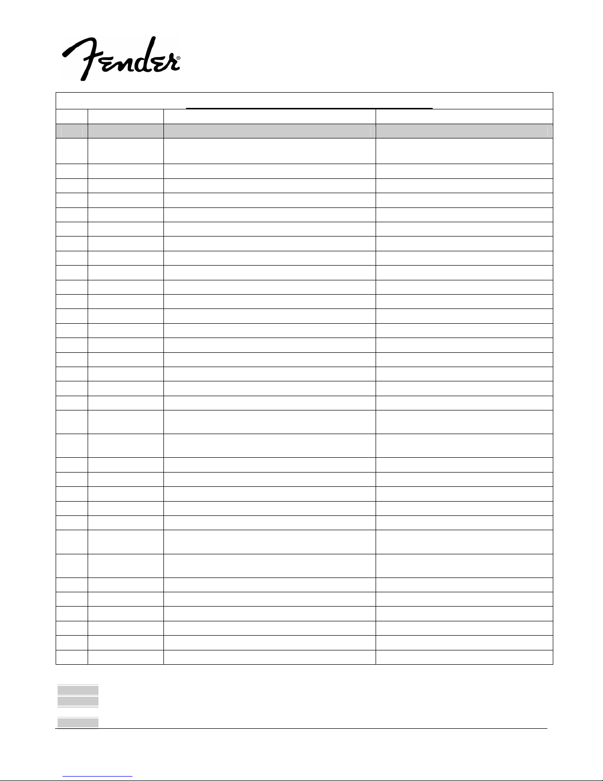
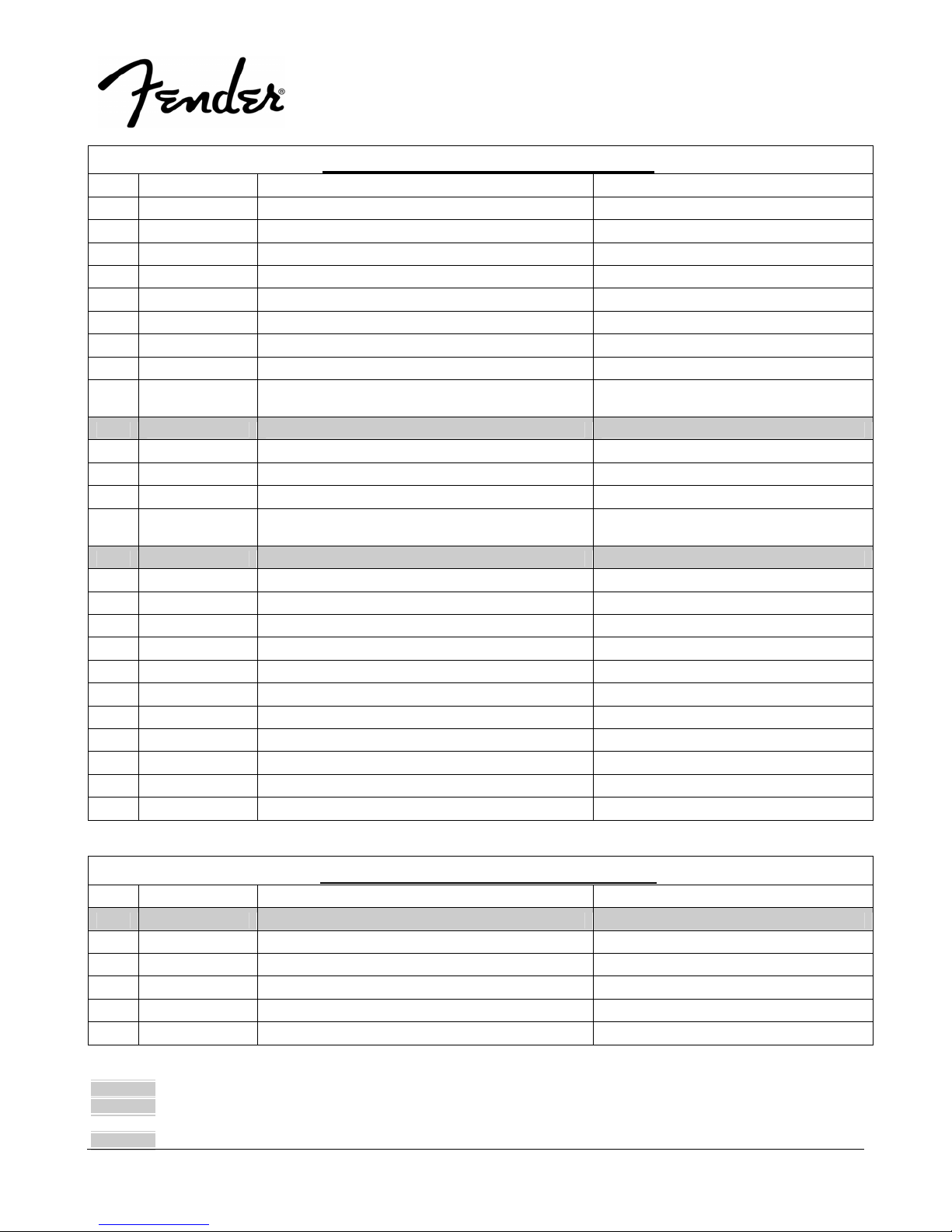
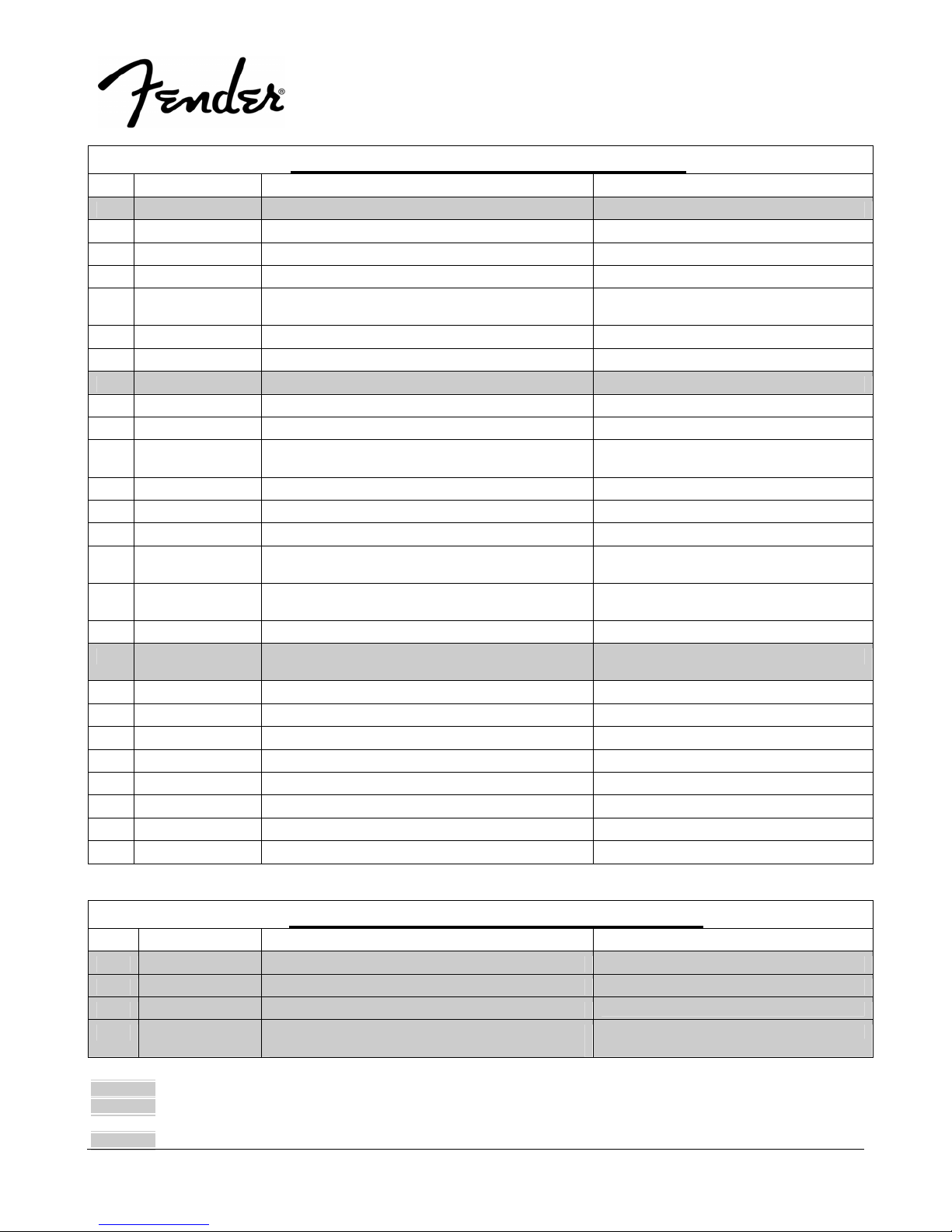
.PARTS LIST:
QTY PART # DESCRIPTION REFERENCE DESIGNATION
1 0074491000 PCB ASSY CD SERVO
14 REF
1 REF *CC 50V 0.015U 10% 0603 C427
5 REF *CC 50V 0.01U 10% 0603 MURATA C460 C465 C466 C467 C519
1 REF *CC 50V 0.01uF 10% 0603 1x2 C430
2 REF *CC 50V 0.033U 10% 0603/1608 1X2 C402 C421
5 REF *CC 50V 0.047uF 10% 0603 1x2 C407 C436-439
2 REF *CC 50V 2200pF 10% 0603 0 .8x1.6 C447 C451
1 REF *CC 50V 2700PF 10% 0603/1608 C431
2 REF *CC 50V 470P 10% 0603/1608 1X2 C434 C435
1 REF *CC 50V 47P 5% 0603 1x2 C428
1 REF *CC 50V 6800P 10% 0603/1608 1X2 C457
1 REF *CE 16V 1000u 20% RL 10X1 6 NICHICON/ ELNA C406
6 REF *CE 16V 100U 20% RLT 6.3X7 ELNA C403 C415 C419 C433 C501 C531
3 REF *CE 16V 220uF 20% RL 8x7 ELNA C401 C503 C511
1 REF *CE 16V 22U 20% RLT 4X7 RC2 ELNA C448
2 REF *CE 16V 3.3U 20% RLT 5X5 C446 C450
3 REF *CE 16V 47U 20% RLT 5X7 ELNA C413 C424 C526
1 REF *CE 50V 10U 20% RLT 4X7 C530
1 REF *CONNECTOR FFC 15P P1.0 STRAIGHT SMD
1 REF *CONNECTOR FFC 20PIN P=1.0MM (HORIZON-
1 REF *CTC 0/30 1.0pF 0.25pF 0805 1.2x2.5 C458
9 REF *CTC 0/60 100pF 5% 0603 0.8x1.6 C463-464 C516-517 C520-524
2 REF *CTC 0/60 15pF 5% 0603 0.8X1.6 C440-441
1 REF *CTC 0/60 56pF 5% 0603 0.8X1.6 C420
6 REF *FERRITE BEAD INDUCTOR BL01RN1A1F1J FB401-406
1 REF *IC CD DSP TC94A58FAG-006 64PIN QFP TO-
1 REF *IC MOTOR DRV W/3.3V REG MM1669XH
1 REF *IC REG NCP1117ST33T3G 3.3V SOT-223 IC406
1 REF *IC RF AMP TA2157FN SSOP24 TOSHIBA IC402
1 REF *IC TA7291SG(5/M)22240239 IC405
1 REF *IC VOLATGE DETECTOR KIA7029 SOT89 KEC IC406
4 REF *INDUCTOR 10UH 500MA SMD 1210 L401-403 L406
2 REF *LED HOLDER L L=9 LED
CD SERVO - PCB ASSEMBLY
*CC 16V 0.1U 10% 0603/1608 1X2 C404-405 C410 C414 C417-418 C423
C432 C502 C504 C514-515 C525 C527
CN402
SIDE ENTRY
CN408
TAL)
IC401
SHIBA
IC403
HSOP28D
8
* Non-serviceable part. Replace complete parent assembly. See PCB EXCHANGE POLICY section above.
shaded Unique Fender® part. Order directly from the FMIC Parts Department.
shaded + * Access to this part or assembly is controlled. Please contact the FMIC Customer Service Department.
** Safety Requirement part. Replacement must match Safety Agency…–Value, if specified –Type, if specified –Approval Mark(s) if on part.
shaded + ** Both a unique Fender® part and a Safety Requirement part as defined above.
PASSPORT
®
PD-150 PLUS
(This is the model name for warranty claims)
.PARTS LIST:
QTY PART # DESCRIPTION REFERENCE DESIGNATION
2 REF *LED SC 2.9X5.4XL0.5 IR 950NM HALF AN-
1 REF *PCB CD/KEY 4/L 10Z FR4 EFPAPD150+05CS17
1 REF *RCF 1/4W 4.7R 5% ATS R549
1 REF *RMG 1/16W 100R 1% 0603 R555
9 REF *RMG 1/16W 10K 1% 0603 HK RESIS-
1 REF *RMG 1/16W 10R 5% 0603 HK RESIS-
1 REF *RMG 1/16W 15K 1% 0603/1608 R518
3 REF *RMG 1/16W 1K 1% 0603/1608 R507 R535 R537
4 REF *RMG 1/16W 2.2K 1% 0603/1608 R420 R446 R447 R505
1 REF *RMG 1/16W 2.2M 5% 0603 R519
4 REF *RMG 1/16W 220R 1% 0603/1608 R401 R404 R407 R516
4 REF *RMG 1/16W 22K 1% 0603 HK RESIS-
1 REF *RMG 1/16W 470K 1% 0603 R520
1 REF *RMG 1/16W 47K 1% 0603 HK RESISTOR/ SAM-
1 REF *RMG 1/16W 5.6K 1% 0603/1608 R522
1 REF *RMG 1/16W 820R 1% 0603 HK RESIS-
4 REF *RMG 1/16W 82K 5% 0603/1608 R510-511 R513-514
1 REF *RMG 1/16W 91R 5% 0603/1608 R405
1 REF *SW DETECTOR PUSH SPST DTS-03-SMT LUP
1 REF *TR 2SA1015-GR(TE2/F/T) RLT TOSHIBA Q401
1 REF *TR PNP 2SB1457 TO-92 RL Q402
2 REF *WAFER 4P P2.0 90DEG JAPAN CN405 CN409
1 REF *X'TAL 16.9344MHZ +/-30PPM AT-51 X401
CD SERVO - PCB ASSEMBLY
LED1-2
GEL+/-10DEG
R506 R517 R521 R524 R534 R536 R538
TOR/SAMSUNG
TOR/SAMSUNG
TOR/SAMSUNG
SUNG
TOR/SAMSUNG
FUNG
R540-541
R501
R502 R504 R523 R542
R503
R515
SW401
9
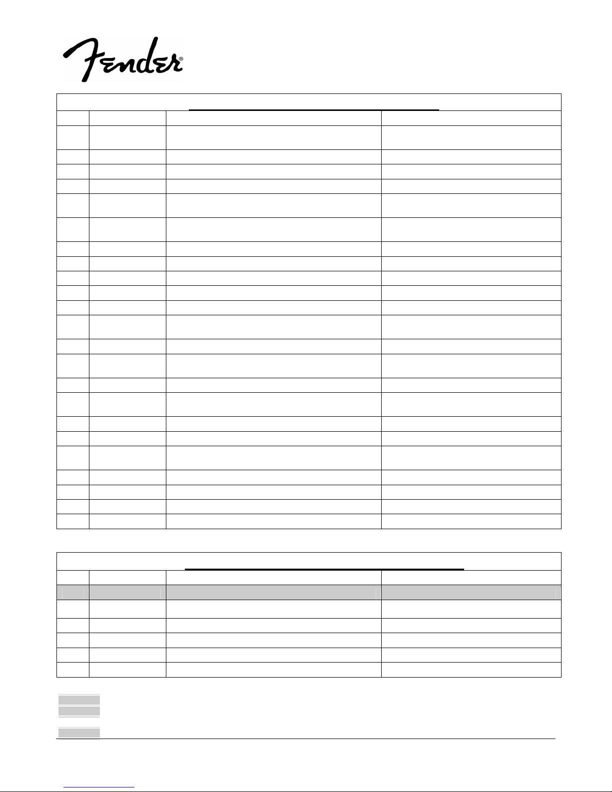
.PARTS LIST:
QTY PART # DESCRIPTION REFERENCE DESIGNATION
1 0074494000 PCB ASSY LCD DISPLAY CONTROL
5 REF *CC 16V 0.1U 10% 0603/1608 1X2 C701-704 C709
1 REF *CC 50V 2.2U 10% 1206 X7R MURATA C708
1 REF *CONNECTOR FFC 20P P1.0 STRAIGHT F J701
1 REF *CRYSTAL 32.768KHZ 2X6 +/-20PPM 6PF Y701
2 REF *CTC 0/60 22pF 5% 0603 0.8X1.6 C706-707
* Non-serviceable part. Replace complete parent assembly. See PCB EXCHANGE POLICY section above.
shaded Unique Fender® part. Order directly from the FMIC Parts Department.
shaded + * Access to this part or assembly is controlled. Please contact the FMIC Customer Service Department.
** Safety Requirement part. Replacement must match Safety Agency…–Value, if specified –Type, if specified –Approval Mark(s) if on part.
shaded + ** Both a unique Fender® part and a Safety Requirement part as defined above.
LCD DISPLAY - PCB ASSEMBLY
10
PASSPORT
®
PD-150 PLUS
(This is the model name for warranty claims)
.PARTS LIST:
QTY PART # DESCRIPTION REFERENCE DESIGNATION
1 REF *DIODE LL4148 SM D701
1 REF *DISPLAY LCD 25X14X10 POS DAI-2011-AHPT
1 REF *IC MCU LCD DRIVER EM78P468NQ QFP-64
1 REF *INSULATION SHEET ASTIGMATISM
1 REF *LED SC 2.9X5.4XL0.5 BL L-7104PBD-A KING-
1 REF *LENS TRANSMIT LIGHT 29X16X9
1 ** REF *PCB LCD/KEY FR4 D/S 1OZ A EF-
3 REF *RMG 1/16W 10K 1% 0603 HK RESIS-
1 REF *RMG 1/16W 270R 1% 0603 HK RESIS-
1 REF *RMG 1/16W 4.7K 1%. 0603/1608. R706
6 REF *SW TACT 6X3MM BODY 4.3MM HEIGHT BLACK SW701-706
1 REF *TR 3904 HFE 100-300 SM Q701
LCD DISPLAY - PCB ASSEMBLY
AMAXKEPO
ELNA
28.8X15.6X0.
BRIGHT
CLEAR/TEXTURE PD250
PAPD150+05CS17
TOR/SAMSUNG
TOR/SAMSUNG
LCD
U701
LENS TRANS
D702
LCD
R701-703
R705
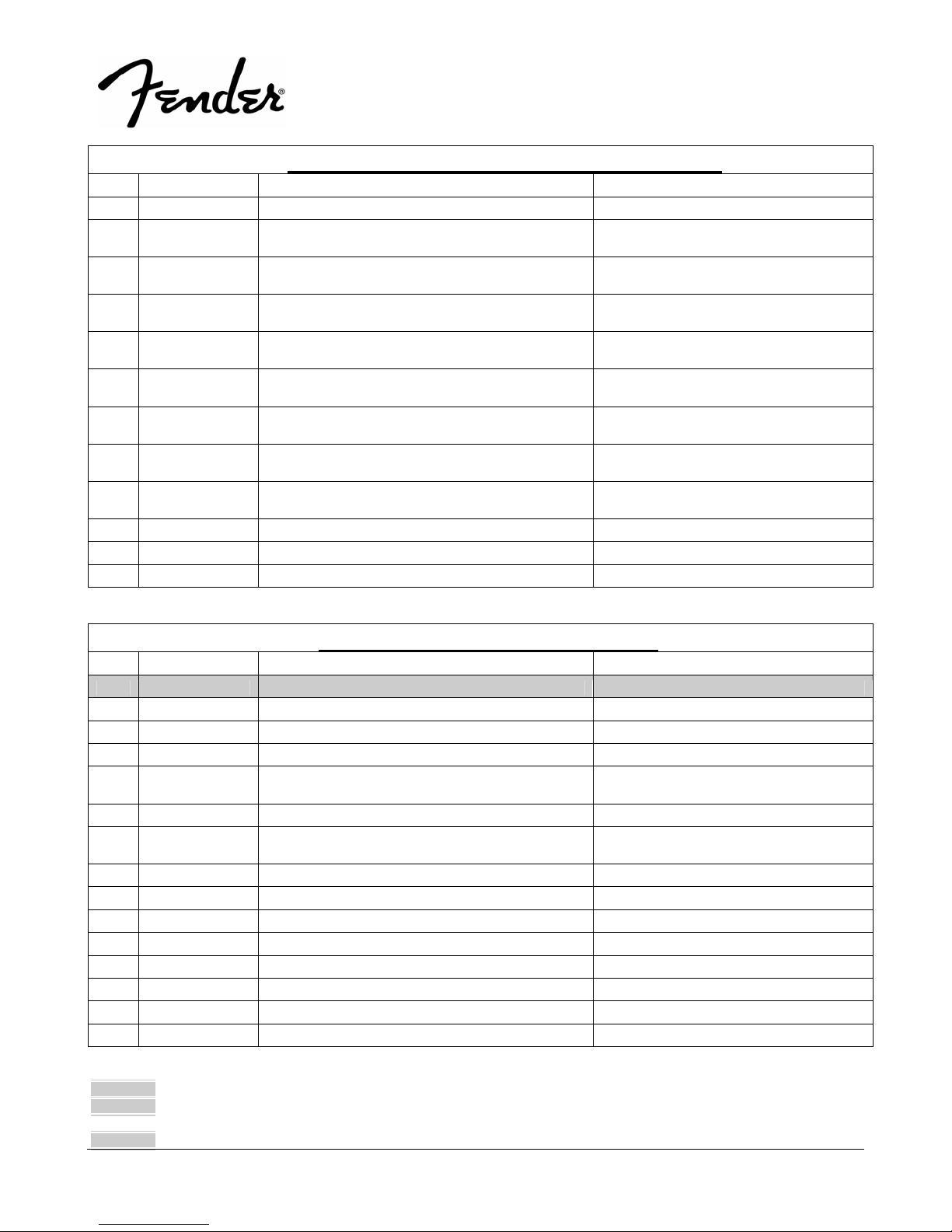
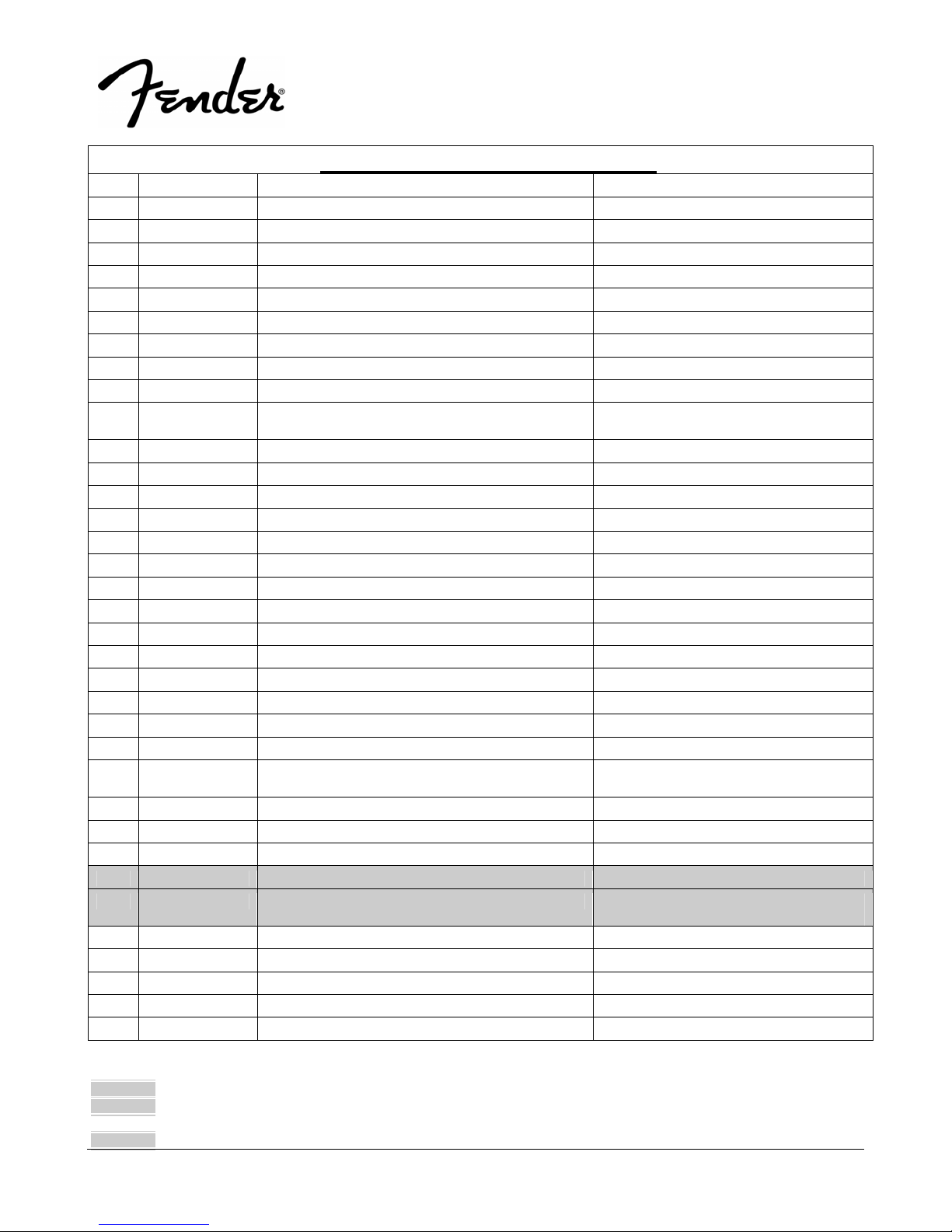
.PARTS LIST:
QTY PART # DESCRIPTION REFERENCE DESIGNATION
1 0074492000 PCB ASSY D-AMP
3 REF *2P ST.WAFER P=2.5 COULOMB CN4-6
5 REF *CC 100V 0.1uF 20% 1206 C18 C21 C45 C48 C58
4 REF *CC 50V 0.015U 10% 0805 1.2X2.0 C19-20 C46-47
16 REF *CC 50V 0.1uF 10% 0805 1.2X2.0 C11-12 C14-15 C17 C25 C27 C36-39
4 REF *CC 50V 1000p 5% 0805 1.25X2.0 MURATA C10 C2 C8 C9
14 REF *CC 50V 220pF 5% 0805 1.2X2.0 C1 C3 C13 C16 C22-23 C28 C35 C40
1 REF *CE 16V 100U 20% RLT 6.3X7 ELNA C66
4 REF *CE 35V 1000UF 20% RL 12.5x20 ELNA C140-143
4 REF *CE 50V 47UF 20% RLT 6.3X11 SHOEI C34 C55 C59-60
4 REF *CM 100V 0.68U 5% RBT 7.5X11.5 MKS2 WIMA C30-33
4 REF *CM 63V 0.68uF 10% RL 5X7.5 C171-174
1 REF *CN ASSY UL1007 #26 L=180 2P F/M P2.5 CN3
1 REF *DZ 1/2W 5.45-5.73 ROHM AT (MTZJ5.6B) D3
4 REF *FERRITE BEAD INDUCTOR BL01RN1A1F1J L5-8
* Non-serviceable part. Replace complete parent assembly. See PCB EXCHANGE POLICY section above.
shaded Unique Fender® part. Order directly from the FMIC Parts Department.
shaded + * Access to this part or assembly is controlled. Please contact the FMIC Customer Service Department.
** Safety Requirement part. Replacement must match Safety Agency…–Value, if specified –Type, if specified –Approval Mark(s) if on part.
shaded + ** Both a unique Fender® part and a Safety Requirement part as defined above.
D-AMP - PCB ASSEMBLY
C41-42 C44 C52 C54
C43 C49-50 C56-57
11
PASSPORT
®
PD-150 PLUS
(This is the model name for warranty claims)
.PARTS LIST:
QTY PART # DESCRIPTION REFERENCE DESIGNATION
4 REF *FERRITE COIL 22UH 20% BL19.2 L1-4
2 REF *IC PW AMP TDA8920BTH/N2 SOT566-3 PHIL-
IPS
1 REF *PCB AMP 94V0 FR4 D/S EFPAPD150+05CS17
5 REF *RMF 1/4W 10K 1% AT R19 R20 R38 R39 R7
2 REF *RMF 3W 1.2K 5% ATS METAL OXIDE R25-26
1 REF *RMG 1/10W 0R 5% 0805 R37
1 REF *RMG 1/10W 10K 5% 0805 R30
4 REF *RMG 1/10W 2.7K 5% 0805 R1-2 R17-18
1 REF *RMG 1/10W 22K 5% 0805 R34
2 REF *RMG 1/10W 27K 5% 0805 R3 R33
2 REF *RMG 1/10W 30K 1% 0805 R40 R41
1 REF *RMG 1/10W 39K 5% 0805 R36
1 REF *RMG 1/10W 8.2K 5% 0805 R32
2 REF *RMG 1/16W 68R 5% 0603/1608 R80-81
10 REF *RMG 1/4W 10R 5% 1206 R4 R8-9 R12 R22-24 R27-29
1 REF *RMG 1/4W 200R 5% 1206 R35
1 REF *RMG 1/4W 22K 1% 1206 R31
4 REF *RMG 1W 22R 5% 2512 R13-16
1 REF *TR 2N3904/PS Q2
2 REF *TR 2N3904TA RLT Q1 Q2
1 REF **, *WAFER 4P P3.96 STRAIGHT MALE CN1
1 REF *WAFER 6 PIN P2.5 CN2
D-AMP - PCB ASSEMBLY
U1 U5
.PARTS LIST:
QTY PART # DESCRIPTION REFERENCE DESIGNATION
1 0074507000 PCB ASSY OUT
2 REF JACK PHONE 4PIN 6.4 LJ-0695A-4R PLASTIC
1 REF **WAFER 4P P3.96 STRAIGHT MALE CON804
OUTPUT JACK - PCB ASSEMBLY
BUSH
.PARTS LIST:
QTY PART # DESCRIPTION REFERENCE DESIGNATION
1 0074493000 PCB ASSY INPUT PD150 PLUS
2 REF *2P ST. WAFER P=2.0 COULOMB CN103-104
4 REF *CC 50V 0.1uF 20% 0805 1. 2x2.0 C109-112
* Non-serviceable part. Replace complete parent assembly. See PCB EXCHANGE POLICY section above.
shaded Unique Fender® part. Order directly from the FMIC Parts Department.
shaded + * Access to this part or assembly is controlled. Please contact the FMIC Customer Service Department.
** Safety Requirement part. Replacement must match Safety Agency…–Value, if specified –Type, if specified –Approval Mark(s) if on part.
shaded + ** Both a unique Fender® part and a Safety Requirement part as defined above.
INPUT - PCB ASSEMBLY
12
PASSPORT
®
PD-150 PLUS
(This is the model name for warranty claims)
.PARTS LIST:
QTY PART # DESCRIPTION REFERENCE DESIGNATION
4 REF *CC 50V 100pF 5% 0805 1.2 x2.0 C105-108
4 REF *CE 25V 100U 20% 5X11 RLT RUBYCON YK C196-199
4 REF *CE 50V 22UF 20% RLT 5X11 SHOEI C101-104
2 REF *DIN SOCKET JY-5033-030GD PCB TYPE MJ101-102
8 REF *DIODE LL4148 SM D101-108
2 REF *IC NJM2068M-#ZZZB DUAL OP AMP U101-102
1 REF *IC NJM7812FA-#ZZZB REGULATOR U305
1 REF *IC NJM7912FA-#ZZZB REGULATOR U306
2 REF *JACK PHONE 4PIN 6.4 LJ-0695A-4R PLASTIC
BUSH
2 0074587000 JACK RCA 2P GOLDEN PLATING RCA101 RCA102
1 REF *JM24182-4P WAFER CN102
1 REF *JM24182-5P WAFER CN106
1 REF *LED HOLDER H L=22 LED102
1 REF **, *PCB INPUT/MIX 94V0 CEM-1 EF-
PAPD150+05CS17
6 0070067000 REAR PHONE JACK 5 PIN PJ101-106
1 REF *RMG 1/10W 1.5K 5% 0805 R123
4 REF *RMG 1/10W 10K 5% 0805 R117-120
8 REF *RMG 1/10W 1K 5% 0805 R101-102 R105-106 R109-110 R113-114
8 REF *RMG 1/10W 33K 5% 0805 R103-104 R107-108 R111-112 R115-116
1 REF *RMG 1/10W 47R 5% 0805 R122
1 REF *SIL 3144D GREEN LED 3MM LED102
3 REF *SW-SLIDE 2P2T SS2214RG9 Y.S.C. SW101-103
1 REF *WAFER 4P P3.96 STRAIGHT MALE CN901
1 REF *WAFER 9PIN P=2.50 CN201A
1 REF *WAFER JM24182-3P CN201B
1 REF *WIRE-CONN 6P P2.5 #26 UL1007 L=245 M/F CN103
INPUT - PCB ASSEMBLY
JP901 JP902
.PARTS LIST:
QTY PART # DESCRIPTION REFERENCE DESIGNATION
1 0074495000 PCB ASSY MIX PD150 PLUS
1 REF *3 PIN SHIELD WIRE ASSY L=130MM CN301
6 REF *CC 50V 0.022U 10% 0805 1.2X2.0 C204 C231-235
2 REF *CC 50V 0.1uF 10% 0805 1.2X2.0 C244-245
6 REF *CC 50V 1000pF 10% 0805 1 .2x2.0 C203 C205-209
4 REF *CC 50V 4700pF 5% 0805 1. 2x2.0 C236-239
* Non-serviceable part. Replace complete parent assembly. See PCB EXCHANGE POLICY section above.
shaded Unique Fender® part. Order directly from the FMIC Parts Department.
shaded + * Access to this part or assembly is controlled. Please contact the FMIC Customer Service Department.
** Safety Requirement part. Replacement must match Safety Agency…–Value, if specified –Type, if specified –Approval Mark(s) if on part.
shaded + ** Both a unique Fender® part and a Safety Requirement part as defined above.
MIXER - PCB ASSEMBLY
13
PASSPORT
®
PD-150 PLUS
(This is the model name for warranty claims)
.PARTS LIST:
QTY PART # DESCRIPTION REFERENCE DESIGNATION
20 REF *CC 50V 47pF 5% 0805 1.2x 2.0 C211-230
7 REF *CE 50V 0.47uF 20% RL 4x7 C247-253
11 REF *CE 50V 1UF 20% RLT 4X5 SSK SHOEI C260 C262 C264-272
2 REF *CE 50V 4.7U 20% RLT 4X7 C246 C263
4 REF *CE 50V 47UF 20% RLT 6.3X11 SHOEI C276-279
1 REF *CN ASSY UL2547 #26 L=210 3P M/M P2.5 CN206
4 REF *DIODE LL4148 SM D205-208
12 REF *IC NJM2068M-#ZZZB DUAL OP AMP U201-212
4 REF *RCF 1/4W 1K 5% ATS R254-255 R258-259
18 REF *RCF 1/4W 27K 5% ATS R202 R208 R273 R300-302 R304-306
6 REF *RCF 1/4W 33K 5% ATS R320-325
8 REF *RCF 1/4W 39K 5% ATS R209-215 R272
1 REF *RCF 1/4W 47R 5% ATS R298
4 REF *RCF 1/4W 56K 5% ATS R226 R315 R319 R327
1 REF *RCF 1/4W 6.8K 5% ATS R289
2 REF *RCF 1/4W 8.2K 5% ATS R218-219
15 REF *RCF 1/4W 82K 5% ATS R221-225 R227-233 R251-253
17 REF *RCF 1/8W 100K 5% AT R234-R250
15 REF *RCF 1/8W 10K 5% AT R216-217 R256-257 R261-R271
4 REF *RCF 1/8W 1M 5% AT R278-R281
4 REF *RCF 1/8W 36K 5% AT R220 R303 R307 R310
4 REF *RMG 1/10W 2.2K 5% 0805 R803-806
4 REF *RMG 1/10W 270K 5% 0805 R125-R128
4 REF *RMG 1/10W 470R 5% 0805 R801-802 R807-808
2 REF *RMG 1/16W 10K 5% 0603 HK RESIS-
TOR/SAMSUNG
2 REF *RMG 1/16W 270K 5% 0603 R129-130
3 REF *TR FET J112-TR1-E3 RLT Q208 Q209 Q210
4 REF *TR RN1241-A(TPE4/F) Q1 Q2 Q3 Q4
4 0074613000 VR RK14K1240 (100KBx2) ALPS VR202 VR206 VR211 VR216
20 0074614000 VR RK14K1240 100KBx2 W/C.C (ALPS) VR201 VR203 VR204-205 VR207-210
1 REF *WIRE-CONN 12P P2.5 #26 UL1007 L=130 F/F CN201
1 REF *WIRE-CONN 4P P2.0 #26 UL1007 L=215 F/F CN204
1 REF *WIRE-CONN 5P P2.54 #26 UL1007 L=300 F/F CN209
1 REF *WIRE-CONN 6P P2.54 #26 UL1007 L=120 F/F CN210
1 REF *WIRE-CONN 6P P2.54 #26 UL1007 L=250 F/F CN208
MIXER - PCB ASSEMBLY
R308-309 R311-314 R316-318
R809-810
VR212-215 VR217-224
* Non-serviceable part. Replace complete parent assembly. See PCB EXCHANGE POLICY section above.
shaded Unique Fender® part. Order directly from the FMIC Parts Department.
shaded + * Access to this part or assembly is controlled. Please contact the FMIC Customer Service Department.
** Safety Requirement part. Replacement must match Safety Agency…–Value, if specified –Type, if specified –Approval Mark(s) if on part.
shaded + ** Both a unique Fender® part and a Safety Requirement part as defined above.
14
PASSPORT
®
PD-150 PLUS
(This is the model name for warranty claims)
.PARTS LIST:
QTY PART # DESCRIPTION REFERENCE DESIGNATION
1 0074508000 PCB ASSY DSP REVERB
1 REF *2P ST.WAFER P=2.5 COULOMB CN403
19 REF *CC 50V 0.1uF 10% 0805 1.2X2.0 C405-406 C412-419 C422-427 C431-432
2 REF *CC 50V 220pF 10% 0805 1. 2x2.0 C407 C409
1 REF *CC 50V 4700pF 10% 0805 1 .2x2.0 C404
1 REF *CC 50V 470pF 10% 0805 1.2X2.0 C408
7 REF *CE 50V 10UF 20% RLT 5X11 SHOEI C401-403 C410-411 C430 C433
1 REF *CE 50V 1UF 20% RLT 5X11 SHOEI C420
2 REF *CE 50V 47UF 20% RLT 6.3X11 SHOEI C428-429
1 REF *CN ASSY UL1007 #26 L=180 2P F/M P2.5 CN402
1 REF *IC AL1101G WAVEFRONT ADC U404
1 REF *IC AL1201G WAVEFRONT DAC U405
1 REF *IC AL3201BG WAVEFRONT DIGITAL REVERB U406
1 REF *IC L78L05ACZ ST U407
3 REF *IC NJM2068M-#ZZZB DUAL OP AMP U401-403
1 REF *JM24182-6P WAFER CN401
1 REF *PCB DSP REVE D/S FR4 10Z REV: D EF-
1 REF *RMG 1/10W 100K 5% 0805 R401
8 REF *RMG 1/10W 10K 5% 0805 R408 R410-411 R416 R418-421
1 REF *RMG 1/10W 1K 5% 0805 R417
4 REF *RMG 1/10W 2.2K 5% 0805 R402-405
3 REF *RMG 1/10W 220R 5% 0805 R406-407 R413
2 REF *RMG 1/10W 4.7K 5% 0805 R409 R412
1 REF *RMG 1/10W 47K 5% 0805 R415
1 REF *RMG 1/8W 10R 5% 1206 R414
1 REF *X'TAL 12.288MHZ +/- 30PPM 49U XL401
DSP REVERB - PCB ASSEMBLY
PAP150D+05CS21
C434
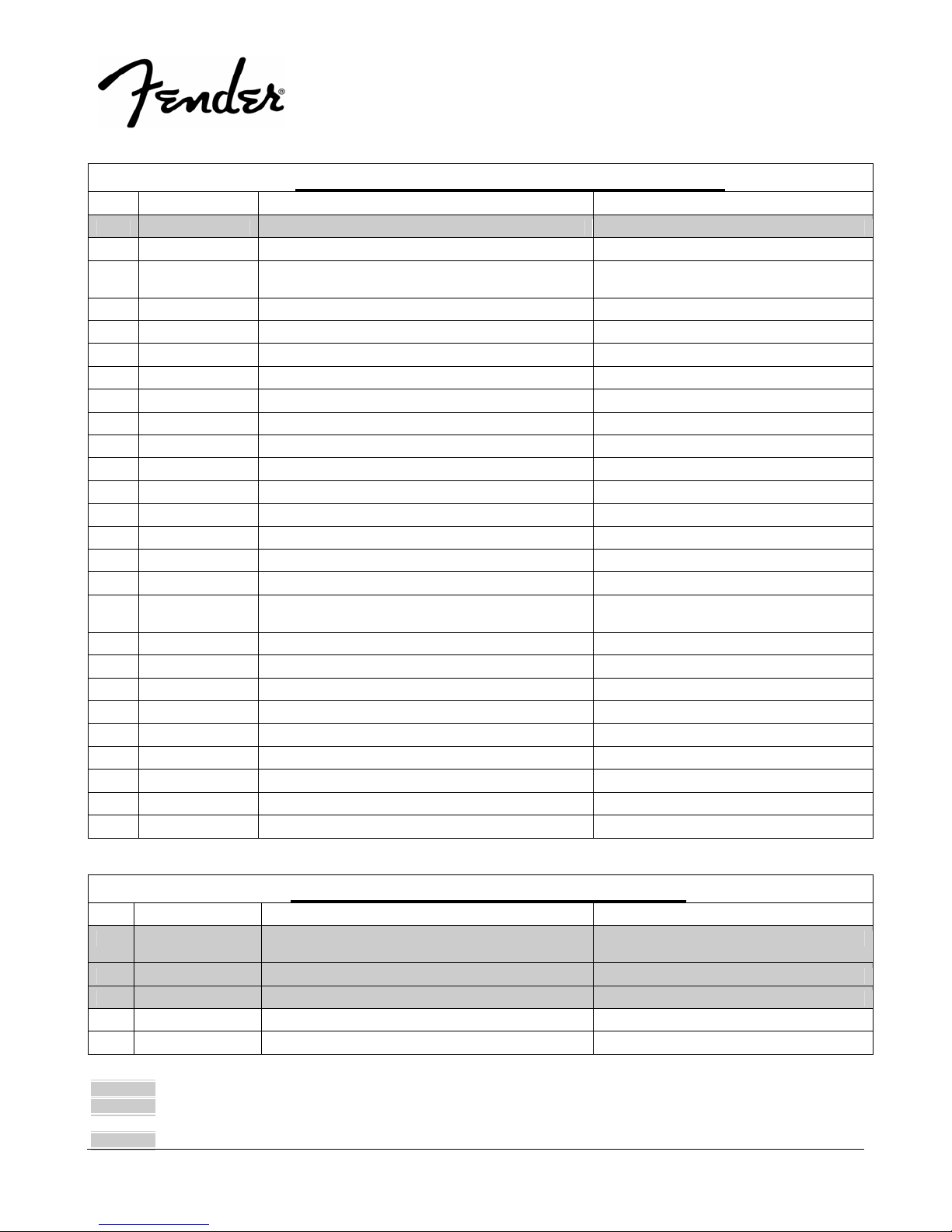
.PARTS LIST:
QTY PART # DESCRIPTION REFERENCE DESIGNATION
1 0074497000 MODULE SMPS AC100-240V 47-53HZ 240W
1 0074490000 **FAN DC 12V 4700RPM 80X80X25
1 0074489000 **FAN DC 12V 40X40X10 REAL
1 REF *COVER-BOTTOM EFPAPD150+05CS17
1 REF *COVER-TOP POWER SUPPLY PD150 PLUS
* Non-serviceable part. Replace complete parent assembly. See PCB EXCHANGE POLICY section above.
shaded Unique Fender® part. Order directly from the FMIC Parts Department.
shaded + * Access to this part or assembly is controlled. Please contact the FMIC Customer Service Department.
** Safety Requirement part. Replacement must match Safety Agency…–Value, if specified –Type, if specified –Approval Mark(s) if on part.
shaded + ** Both a unique Fender® part and a Safety Requirement part as defined above.
SMPS – MODULE ASSEMBLY
PD150
15
PASSPORT
®
PD-150 PLUS
(This is the model name for warranty claims)
.PARTS LIST:
QTY PART # DESCRIPTION REFERENCE DESIGNATION
2 0074591000 **, *FUSE T3.15A 250V 5X20MM UR & SEMKO POWER INLET
1 REF *HALO BUSHING 0813C
2 REF *M3 NUT NI FAN
2 REF *M3 NUT NI POWER INLET
1 REF **, *CHOKE EARTH TOROIDAL 200UH #18
1 REF *NUT HEX M4 KS-966N-1
1 REF *NUT HEX M4 RING T'NAL
1 0070264000 POWER INLET SOCKET SC9F-21
1 REF *RUBBER SUPPORT PCB 10X10X7
3 REF *SCREW BH M3X 5 MM BZ CRO SS COVER BOTTOM
1 REF *SCREW B-TITE BIND M4X8 CROSS-RECESS
4 REF *SCREW D3X6 S-TITE BH,BK TOP COVER
4 REF *SCREW M3X10 W/S&F WASHER (BLK) FAN
4 REF *SCREW M3X10 W/S&F WASHER (BLK) PCB SMPS
2 REF *SCREW MACHINE PAN M3X10 CROSS-
2 REF **, *SCREW S-TITE BIND M3X12 CS-RECESS
1 REF *SPACER SSRS4-5-01 P150 BOTTOM COVER
1 0074485000 SWITCH ROCKER 2PIT 6A/250V UL/SEMKO
1 REF **, *TRE 12X6X4 TOROIDAL KS-9 66N-1 L304
1 REF *WASHER INT-TOOTH M4X0.8X8.5 BZ KS-966N-1
1 REF *WASHER INT-TOOTH M4X0.8X8.5 BZ RING T'NAL
1 REF *WASHER METAL M4X0.8X10 BZ SPACER
6 REF *WASHER SPRING M3X0.9X5.5 BZ TOP COVER
1 REF *WASHER SPRING M4X1X7 NI KS-966N-1
1 REF *WASHER SPRING M4X1X7 NI RING T'NAL
1 REF **, *WIRE-CONN 3P P3.96 #18 UL1015 L=45 F/M IN LET
SMPS – MODULE ASSEMBLY
PCB/GND
WIRE GRE/YEL
SPACER
BZ
POWER INLET
RECESS BZ
FAN
BZ
R13-0-6
.PARTS LIST:
QTY PART # DESCRIPTION REFERENCE DESIGNATION
24 0074481000 KNOB-SMALL 23.6X23.6X20.5
1 0074483000 KNOB-CD EFPAPD250 CD
1 0074498000 SPEAKER CABINET ASSEMBLY, PD150+
1 0074496000 COMPLETE FRONT PANEL ASSEMBLY,
* Non-serviceable part. Replace complete parent assembly. See PCB EXCHANGE POLICY section above.
shaded Unique Fender® part. Order directly from the FMIC Parts Department.
shaded + * Access to this part or assembly is controlled. Please contact the FMIC Customer Service Department.
** Safety Requirement part. Replacement must match Safety Agency…–Value, if specified –Type, if specified –Approval Mark(s) if on part.
shaded + ** Both a unique Fender® part and a Safety Requirement part as defined above.
MISCELLANEOUS MATERIALS
PD150+
 Loading...