

SERVICE MANUAL
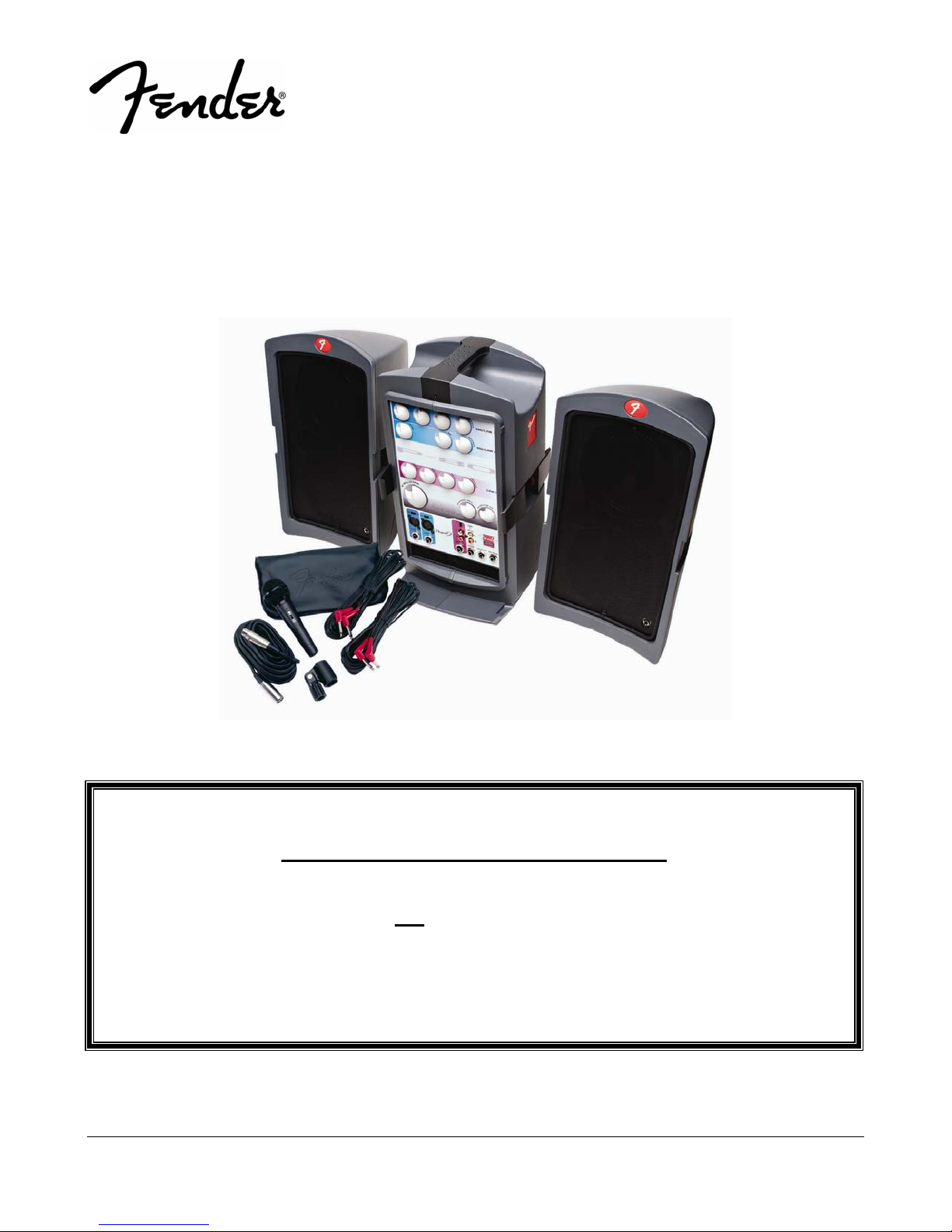
PASSPORT® P-80
(This is the model name for warranty claims)
p/n 069-1003-000
WARRANTY SERVICE PROCEDURES
Warranty field service of the Passport® P-80 will be limited to replacement of defective
PCB Assemblies and all other parts not
repairs can of course be to the component level at the Service Center’s discretion. For
non-warranty component level repairs all parts listed as “REF” in the Parts List must be
sourced from suppliers other than FMIC.
Fender Musical Instruments Corporation, 8860 East Chaparral Road Suite 100 Scottsdale, AZ 85250
ATTENTION:
marked as “REF” in the Parts List. Non-Warranty
Issued: October, 2007

2
PASSPORT
(This is the model name for warranty claims)
October, 2007
IMPORTANT NOTICE
®
P-80
• Copyright © 2007 FMIC. All rights reserved. All
information contained herein is CONFIDENTIAL
and PROPRIETARY and is the property of
Fender® Musical Instruments Corporation. It is
not to be sold or assigned to another party and is
disclosed solely for use by Fender Authorized
Service Centers for purposes of product service
and maintenance. All information is not to be disclosed to others without the expressed permission
of Fender® Musical Instruments Corporation. All
PARTS LIST CODES
The description codes used in the itemized Parts Lists are defined below:
CAPACITOR
CAP AE = Aluminum Electrolytic
CAP CA = Ceramic Axial
CAP CD = Ceramic Disk
CAP CR = Ceramic Radial
CAP MPF = Metalized Polyester Film
CAP MY = Mylar
CAP PFF = Polyester Film/Foil
RESISTOR
RES CC = Carbon Comp
RES CF = Carbon Film
RES FP = Flame Proof
RES MF = Metal Film
RES MOX = Metal Oxide
RES WW = Wire Wound
CODES
CODES
specifications are subject to change without notice. This information and any copies produced
electronically or otherwise must be surrendered
upon demand of Fender® Musical Instruments
Corporation.
• Parts marked with two asterisks (
required use of that specific part. This is necessary for RELIABILITY and SAFETY requirements.
DO NOT USE A SUBSTITUTE!
HARDWARE
BLX = Black Oxide
CR = Chrome Plated
HWH = Hex Washer Head
M = Machine Screw
NI = Nickel Plated
OHP = Oval Head Phillips
PB = Particle Board
PHP = Pan Head Phillips
PHPS = Pan Head Phillips Sems
SMA = Sheet Metal "A" Point
SMB = Sheet Metal "B" Point
SS = Stainless Steel
TF = Thread Forming
ZI = Zinc Plated
CODES
**) indicate the

PASSPORT
(This is the model name for warranty claims)
®
P-80
SPECIFICATIONS
Model Name: PASSPORT P-80
Release Number: PR600
Part Number: (120V, 60Hz) US: 069-1003-000
(240V, 50 Hz) AUS: 069-1003-030
(230V, 50 Hz) UK: 069-1003-040
(230V, 50 Hz) EUR: 069-1003-060
(100V, 50 Hz) JPN: 069-1003-070
Frequency Response: 20 Hz to 40 kHz ± 1 dB (at send output)
30 Hz to 30 kHz ± 1 dB (at speaker output, with processor threshold exceeded)
Distortion: < 0.1%, 20 Hz to 20 kHz, 1dB below rated output
Signal to Noise Ratio: > 80 dB @ 1W, “A” WTD
Power Output: 80W continuous average power, 4
Input Impedance:
(Channels 1-2-3 XLR and 1/4”) “Mic” switch position: 2 k
“Line” switch position: 66 k
(Phono Channel 1/4”) 78 k
Max. Input Level: Mic: -7 dBu
Line: 30 dBu
Stereo: 26 dBu
Return Input Impedance: 47k
Fuse type: T4AH, 250V
Passport System: Width: 610 mm (24 in.)
Height: 541 mm (18 in.)
Depth: 254 mm (10 in.)
Weight: 11.83 kgs (26 lbs)
Speakers: Width: 245 mm (9.65 in.)
Height: 439 mm (17.5 in.)
Depth: 241 mm (9.5 in.)
Weight: 3.3 kgs (7.25 lbs)
Power Tower: Width: 254 mm (10 in.)
Height: 451 mm (18 in.)
Depth: 178 mm (7 in.)
Weight: 5.23 kgs (11.5 lbs)
Tower Footprint: 241 x 298 mm (9.5 x 11.75 in.)
Microphone: Dynamic Cardioid, balanced
Microphone Cable: XL -Male to XL-Female, 6 m (20 feet)
Speaker Cables: 1/4 in. to 1/4 in., 9 m (30 feet)
Ω
Ω
Ω
Ω, both channels driven with THD < 1%
Ω
3
0 dBu is referenced to 0.775 volts rms
Product specifications are subject to change without notice

SERVICE NOTES
The following describes the procedure to dismantle
the P-80 Cabinets.
STEP A: P-80 CABINETS
A1. Unscrew four M4 machine screws on each
side of the left and right hatches.
A2. Unscrew two M3 pan-head machine screws
on the handle cover and detach it.
A3. Place the unit upside down. Unscrew eight M4
self-tapping screws off the foot standers.
A4. Detach the foot standers. There are six M3
self-tapping screws in the middle portion.
A5. Unscrew three M3 self-tapping screws located
on the right-hand-side.
A6. Place the unit in the normal position.
A7. Locate the four M3 and two M4 self-tapping
screws on the top and unscrew them.
A8. Separate the left and right cabinets.
A9. Locate the UHF and VHF antennas on the
right and left cabinets respectively.
A10. De-solder both antennas.
A11. Unscrew three M3 self-tapping screws on left
and right side panels of the tower metal assembly.
A12. Unscrew eight M2.6 and six M3 self-tapping
screws.
A13. Detach the left and right metal side panels.
A14. Detach the 8-pin antenna connector.
A15. Detach the top metal cover.
A16. Unscrew seven M3 self-tapping screw on the
rear panel
A17. Detach all connectors.
A18. The procedure is completed.
STEP B: P-80 MIXER PCB
B1. Detach 14 knobs and their nuts.
B2. Detach the Reverb PCB assembly.
PASSPORT
(This is the model name for warranty claims)
B3. Unscrew nine M3 machine screws from the
mixer PCB assembly.
B4. Detach all connectors.
B5. The procedure is completed.
STEP C: P-80 DSP REVERB PCB
C1. Detach all connectors.
C2. The procedure is completed.
STEP D: P-80 INPUT PCB
D1. Unscrew six screws and nuts from the front
panel.
D2. Detach all connectors.
D3. The procedure is completed.
STEP E: P-80 POWER AMP PCB
E1. Unscrew four screws connecting the heatsink
to the side brackets (two on either side of
tower).
E2. Detach all connectors.
E3. The procedure is completed.
STEP F: P-80 SMPS PCB
F1. Unscrew three screws from the front panel.
F2. Detach all wiring and connectors.
F3. Unscrew six screws from the top cabinet of
the SMPS.
F4. Unscrew three screws from the bottom cabi-
nets of the SMPS.
F5. Detach the spacer from the wiring of the
SMPS.
F6. Unscrew the earthing M4 nut.
F7. Detach the mains connector from the AC inlet.
F8. Unscrew five screws from the SMPS PCB as-
sembly
F9. The procedure is completed.
P-80
®
4

PCB EXCHANGE POLICY
Parts marked with a single asterisk (
Lists are not field replaceable. If a failure due to
one of these components is detected, please con-
*) in the Part
CIRCUIT DESCRIPTION
This section provides concise information about new
or unusual circuitry designs incorporated into this
amplifier model. The purpose is to aid the service
technician by providing insight into the design areas
most likely to become obstacles in troubleshooting.
Information is focused for its effective use while
maintaining the security of Fender® proprietary information wherever possible.
The P-80 consists of the following modules.
1. Mixer Section
2. Digital Reverb Section
3. Signal Processor Circuit and System EQ Circuit
4. Power Amplifier
5. Switch Mode Power Supply Unit (SMPSU)
Mixer Section
The mixer section is mainly made up of operational
amplifiers as gain stages and therefore a technical
description will not be used here. Following is a basic circuit description to familiarize you with the
layout of the circuit.
The Mic/line section is made up of 3 microphone /
line inputs each with a first stage preamplifier for
balanced or unbalanced inputs (locate on the mixer
board). Line inputs can operate as either balanced
or unbalanced if TRS or TR 1/4” jacks are used respectively. Gain selection of 1dB/+30dB is made by
switching a different value resistor in the input
stage. At this point on channel one, the signal is
picked off for the VIP control ducking circuit made
up of U1B. After the input stage there is one knob
for contour control, followed by an auto-pad level
control where the signal splits off into the rev/aux
bus and main signals with the main signals going to
a pan circuit. Here the main signal is split between
5
®
PASSPORT
(This is the model name for warranty claims)
tact the FMIC Customer Service Department to
order the complete PCB Assembly.
left and right channel signal bus. Channel three also
has an additional input via a pair of RCA connectors
where the signals are summed into mono which
may be used as an auxiliary audio signal input. This
circuit consists of an auto-pad level control, low frequency and high frequency tone controls, and a
rev/aux send control.
The audio bus is connected to three FETs that perform ducking of the signals on the bus with the
exception of channel one which is the drive circuit
for the VIP ducking circuit. This function is provided
by U1B.
Bus signals are buffered by U8A and drive the tape
out connections and the main master level control
circuitry made up of U9A. Rev/Aux signals are buffered by U12B and feed the mono aux send output.
The main level control is auto-pad configured and
drives the speaker EQ circuitry made up of U10A.
Note: Channel 1 Mic/Line reverb function will be affected by VIP control making announcements on
Channel 1 dry.
The mixer board also contains part of the signal
processor circuit and the system EQ circuit for the
power amplifier. These circuits are an integral part
of the power amplifier and appear after the return
signal path.
These circuits will all be discussed later in this
document.
Digital Reverb Section
The DSP Reverb PCB module receives the input
REV/AUX signals at pin 4 of connector CN401. The
P-80

DSP Reverb’s IC’s consist of U404 (AL1101 ADC),
U405 (AL1201 DAC), and U406 (AL3201B). The
outputs from U405 are fed to U402B and then buffered by U402A before feeding back to pin 6 of CN
401.
Signal Processor Circuit and System EQ Circuit
The signal processor is partially located on the
mixer board but is an integral part of the power amplifier section. The operation of this circuit is
performed by filtering the signal from U11A which
drives the bases of Q5 and Q7 to control the voltage level at FETs Q4 and Q6 respectively. This in
turn changes the filter characteristics of circuits
which at low levels boosts the low and high frequencies of the signal. At high signal levels with the
gate voltages approaching or at 0v, the circuit lowers the boost of the low frequencies in response.
This circuit is post aux return and therefore does
not modify the response of the signal at the aux
send outputs.
Power Amplifier
Note: In cases where the amplifier circuits are identical between the left and right channel. Only
components related to the left channel will be discussed for simplicity.
The first stage of the power amplifier is made up of
op amp U201A that acts as the input buffer and
muting circuit for minimization of turn on/off pops.
Q202 in balance with the input resistors of this circuit are designed to provide a deep muting effect.
This circuit will be called into action if the temperature of the heat sink also rises above 80 degrees
Centigrade. (Typical HS temperature is around 50
for normal operation). The output of the first stage
feed trimmer resistor VR201 which are part of the
balanced input section of low noise op-amp U203A
which sets the amplifier gain (factory set at approximately 30.5dB). The output of the second
stage directly drives the biased gates of lateral
power FETs Q205 and Q208.
PASSPORT
(This is the model name for warranty claims)
Speaker short circuit protection is provided by
U203B. This is accomplished when the output is
shorted to ground, the normal differential signal applied to U203B is absent at the negative terminal
while at the same time, the second stage is now
forced into open loop gain. The drive signal is integrated into C211 forcing a positive voltage at the
output of U203B that pulls the gate of FET Q207
into conduction from its previous negative bias off
point, nulling the output of U203A. With the output
of U203A minimized the output current of the amplifier is minimized until the short is removed. At this
time, C211 will discharge allowing normal operation
of the amplifier. Note: Some small DC offset will be
present when the amplifier is in the short circuit protect mode.
The power amplifier board also provides the ±15v
for the mixer/reverb boards as well as the supply for
the SMPSU FAN and the LED PCB which indicated
power. The power amplifier board is also connected
to the GM type fuse holder and aux DC power input
connector.
Switch Mode Power Supply Unit (SMPSU)
This unit is not recommended to be serviced in
the field except by replacing the complete module as a total assembly.
The following information is provided to assist in the
trouble shooting of the unit. Please not that the
mains fuse must be replaced with exactly the same
grade of fuse for safety regulations and to avoid risk
of damage and potential fire hazard.
The mains input to the SMPSU allows for operation
from 100V to 240V. The output of the SMPSU is
±36V DC for the main power supply rails of the
power amplifier. The unit also has connectors for
mains power input, mains power switch and chassis, earth and signal grounds.
Service Tip: You can connect to the aux DC input
(with GM fuses installed) to test the output voltage
to the rails before you open the set for service to
get an indication of a possible power supply fault as
it is connected to the rail output. Do not short these
terminals!
P-80
®
6

The SMPSU incorporates protection circuits other
than the fuses including over current protection. All
parts contained in the SMPSU should be considered to be safety parts and should be replaced with
only exact where service can be provided by properly licensed and trained repair technicians. This
includes the dust filter as well as it has a fire hazard
rating. Please be aware that voltages contained
in this module are deadly.
Service Notes on Changes and Updates
7
®
PASSPORT
(This is the model name for warranty claims)
Refer to the mixer schematic diagram of this manual for the following change. A 0.01uF mylar film
capacitor has been added to the VIP ducking circuit
to prevent a slight hum that may be heard as an artifact at the tail of the ducking action. This was
mainly detected on UL voltage settings. This capacitor is added at the junction of R18 (1Mega ohm)
and D16 and the Source (Ground) of FET Q3
(J112). This modification should be performed on
individual units that are listed below by S/N. All
other UL units have been modified by the factory.
P-80
PASSPORT
®
P-80
(This is the model name for warranty claims)
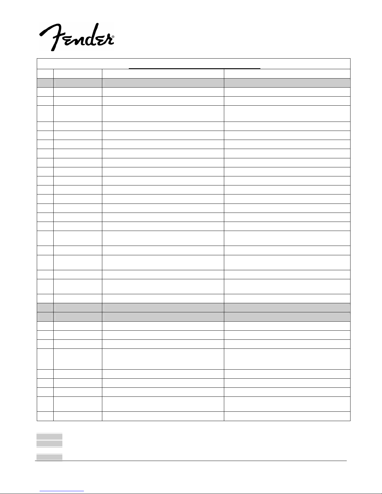
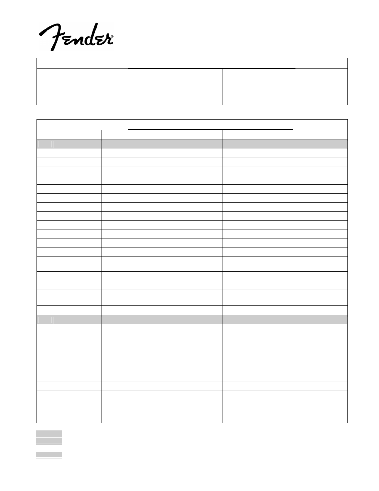
.PARTS LIST:
QTY PART # DESCRIPTION REFERENCE DESIGNATION
1.0 0074726000 PCB ASSY MIXER
1.0 REF FRONT PANEL P80
4.0 REF CC 50V 100P 10% RL 5X3 C3-4 C15-16
11.0 REF CC 50V 27P 10% RL 5X3 C9 C11 C21 C23 C37 C43 C52 C62 C78-80
4.0 REF CM 100V 0.001UF 10% RL 5x7.5 C20 C41 C83-84
1.0 REF CM 100V 0.01UF 10% RL 6x7.5 C87
2.0 REF CM 100V 0.1UF 10% RL 9x11 CENTRALAB C85-86
2.0 REF CM 100V 0.0015UF 10% RL 5X7.5 C7 C18
2.0 REF CM 100V 0.015UF 10% RL 6x9.5 C8 C19
2.0 REF CM 100V 0.0022U 10% 5x7.5 C63 C67
1.0 REF CM 100V 0.022UF 10% RL C42
2.0 REF CM 100V 0.0047UF 10% RL 5.3X7.5 C54-55
2.0 REF CE 25V 47U 20% RLR 5X11 ELNA C47-48
6.0 REF CE 50V 1U 20% RLR 5x11 ELNA C6 C10 C22 C35 C39 C82
4.0 REF CE 50V 2.2uF 20% RL 5x11 C1-2 C13-14
7.0 REF CE 50V 0.47uF 20% RL 5x11 C5 C17 C49 C51 C53 C61 C75
2.0 REF CE 50V 0.47U 20% RLR 5X11
ELNA/NCC/MATSUSHITA
1.0 REF CE 50V 4.7uF 20% RL 5x11 C66
1.0 REF CE 50V 4.7U 20% RLR 5x11
ELNA/NCC/MATSUSHITA
2.0 REF CE 50V 47uF 20% RL 8x12 C76-77
1.0 REF PCB MIXER EF040C S/S 94HB 1OZ REV:A
P50
1.0 REF WAFER JM24182-3P CN8
4.0 0070067000 PJ6-09-5STEREO JACK W/O NUT 5P PJ1-2 PJ4 PJ6
2.0 0070068000 MONO JACK PJ6-09-3 W/O NUT DIAMOND PJ5 PJ7
8.0 REF WASHER METAL M3X0.3X4 WZ MIX/RCA
2.0 REF FIBRE WASHER M3X0.8X8MM MIXER PCB
6.0 REF S-TITE 3X8 (BLK) MIC JACK
15.0 REF SCREW B-TITE BIND HEAD M3X8 CROSS-
RECESS BZ
MIXER- PCB ASSEMBLY
C64-65
C12
LED PCB MIXER PCB
RCA JACK U-BAR
8
3.0 REF SW COVER 2751-11-0 SW-SLIDE
9.0 REF IC TL072CP DUAL FET OP AMP TI U2 U4 U6-12
2.0 REF IC LM833N NS U1 U3
1.0 REF IC TL072CDR DUAL J-FET INPUT OP-AMP
(SMD)
1.0 REF SHIELD PLATE 4132-4741-0 P150
* Non-serviceable part. Replace complete parent assembly. See PCB EXCHANGE POLICY section above.
shaded Unique Fender® part. Order directly from the FMIC Parts Department.
shaded + * Access to this part or assembly is controlled. Please contact the FMIC Customer Service Department.
** Safety Requirement part. Replacement must match Safety Agency…–Value, if specified –Type, if specified –Approval Mark(s) if on part.
shaded + ** Both a unique Fender® part and a Safety Requirement part as defined above.
U13
PASSPORT
®
P-80
(This is the model name for warranty claims)
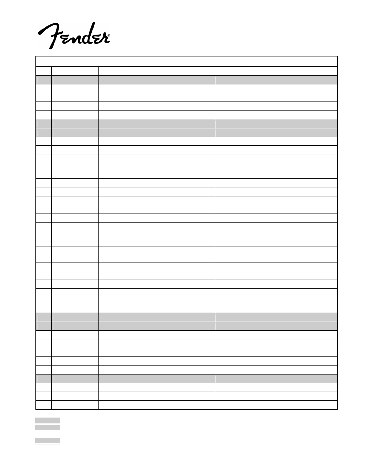
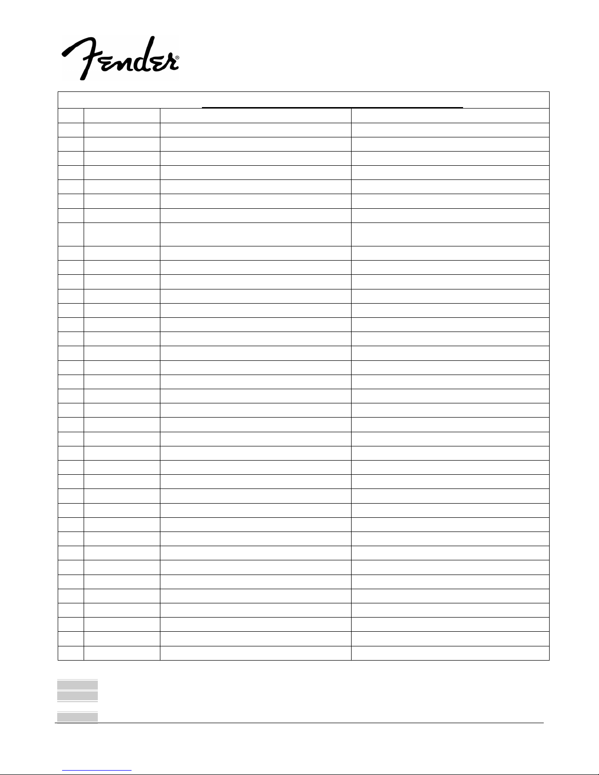
.PARTS LIST:
QTY PART # DESCRIPTION REFERENCE DESIGNATION
1.0 0074733000 MIC JACK BKT 2751-9-0
6.0 REF WASHER M13 4132-5041-0 PHONE JACK
6.0 REF T-NUT M12 4132-5031-0 PHONE JACK
2.0 REF U-BRACKET
4.0 REF CS-0813 PCB SUPPORT
1.0 0070536000 KNOB A 1463-8301-1 P150
13.0 0070537000 KNOB B 1463-8401-1 P150
1.0 REF SHEET FRONT FOR P50
6.0 REF RCF 1/8W 10K 5% AT R11 R65 R80 R90 R129 R138
9.0 REF RCF 1/8W 100K 5% AT R20 R38 R76 R86 R92 R95 R122 R139 R145
6.0 REF RCF 1/8W 1M 5% AT R17 R19 R108 R132-133 R135
2.0 REF RCF 1/8W 110K 5% AT R82 R120
3.0 REF RCF 1/8W 2.2M 5% AT R16 R107 R109
11.0 REF RCF 1/4W 1K 5% ATS R1-3 R6 R15 R25-27 R30 R88 R148
1.0 REF RCF 1/4W 11K 5% ATS R131
6.0 REF RCF 1/4W 12K 5% ATS R9 R14 R33 R37 R102 R105
4.0 REF RCF 1/4W 27K 5% ATS R67 R69 R71 R73
11.0 REF RCF 1/4W 33K 5% ATS R4-5 R7-8 R28-29 R31-32 R93-94 R143
MIXER- PCB ASSEMBLY
9
9.0 REF RCF 1/4W 39K 5% ATS R10 R13 R34 R36 R100-101 R123 R130 R141
3.0 REF RCF 1/4W 470R 5% ATS R22 R24 R136
1.0 REF RCF 1/4W 56K 5% ATS R124
5.0 REF RCF 1/4W 6.8K 5% ATS R83 R103-104 R106 R121
8.0 REF RCF 1/4W 82K 5% ATS R12 R35 R40 R42 R77 R81 R126 R128
1.0 REF RMF 2W 3.3R 5% ATS METAL OXIDE R140
6.0 0070083000 VR RK14K1240 100KBx2 W/C.C (ALPS) VR1 VR6 VR15-16 VR18 VR20
8.0 0070082000 VR RK14K1240 (100KBx2) ALPS VR2-4 VR7-8 VR14 VR21-22
11.0 REF DIODE 1N4148TA NS D1-8 D13 D15-16
1.0 REF TR FET J112 Q4
4.0 REF TR FET J112-TR1-E3 RLT Q1 Q3 Q8-9
1.0 REF TR MPS A56 VCE 80V NS Q5
1.0 REF TR MPS A56 VCE 80V NS RL T Q11
3.0 0070443000 SW-SLIDE 2P2T SS2214RG9 Y.S.C. SW1-2 SW4
1.0 REF CN ASSY UL1007 #26 L=80 15P F/M P2.5 CN1
1.0 REF CN ASSY UL2547 #26 L=170 3P M/M P2.5 CN3
1.0 REF CN ASSY UL2547 #26 L=210 3P M/M P2.5 CN4
* Non-serviceable part. Replace complete parent assembly. See PCB EXCHANGE POLICY section above.
shaded Unique Fender® part. Order directly from the FMIC Parts Department.
shaded + * Access to this part or assembly is controlled. Please contact the FMIC Customer Service Department.
** Safety Requirement part. Replacement must match Safety Agency…–Value, if specified –Type, if specified –Approval Mark(s) if on part.
shaded + ** Both a unique Fender® part and a Safety Requirement part as defined above.
PASSPORT
®
P-80
(This is the model name for warranty claims)
.PARTS LIST:
QTY PART # DESCRIPTION REFERENCE DESIGNATION
1.0 REF CN ASSY UL2547 #26 L=250 3P F/M P2.5 CN5
1.0 REF CN ASSY UL1007 #26 L=180 2P F/M P2.5 CN6
1.0 REF CN ASSY UL1007 #18 L=100 2P F P3.68 CN7
MIXER- PCB ASSEMBLY
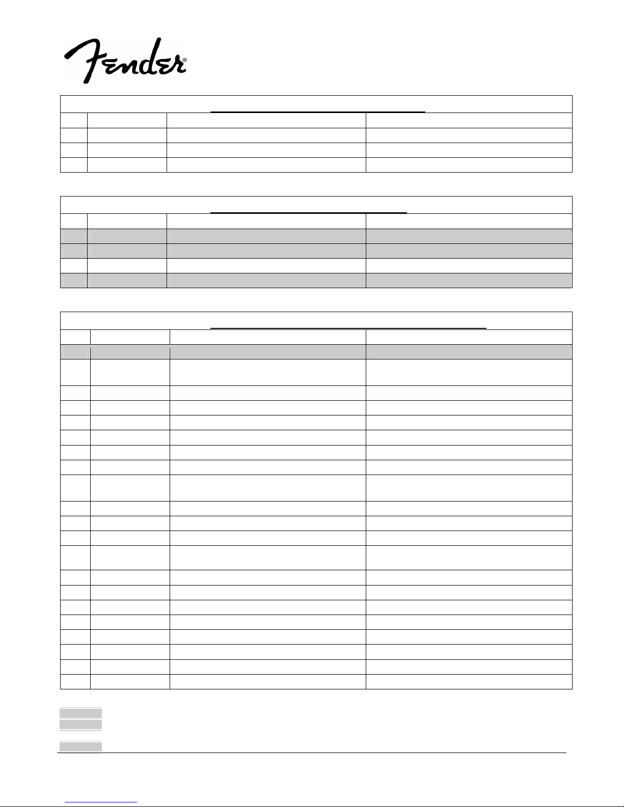
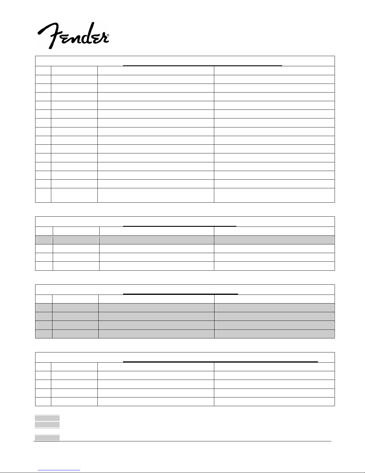
.PARTS LIST:
QTY PART # DESCRIPTION REFERENCE DESIGNATION
1.0 0074728000 PCB ASSY RCA
1.0 0074734000 4RCA JACK HSP-204V-03 GP RJ1
1.0 REF WAFER 15P ST. P=2.5 COULOMB CN1
2.0 0070078000 MIC JACK SVP561P-R MJ1-2
RCA- PCB ASSEMBLY
.PARTS LIST:
QTY PART # DESCRIPTION REFERENCE DESIGNATION
1.0 0074508000 PCB ASSY DSP REVERB
19.0 REF CC 50V 0.1uF 10% 0805 1.2X2.0 C405-406 C412-419 C422-427 C431-432 C434
DSP REVERB- PCB ASSEMBLY
10
2.0 REF CC 50V 220pF 10% 0805 1.2x2.0 C407 C409
1.0 REF CC 50V 470pF 10% 0805 1.2X2.0 C408
1.0 REF CC 50V 4700pF 10% 0805 1.2x2.0 C404
1.0 REF CE 50V 1UF 20% RLT 5X11 SHOEI C420
7.0 REF CE 50V 10UF 20% RLT 5X11 SHOEI C401-403 C410-411 C430 C433
2.0 REF CE 50V 47UF 20% RLT 6.3X11 SHOEI C428-429
1.0 REF JM24182-6P WAFER CN401
1.0 REF X'TAL 12.288MHZ +/- 30PPM 49U XL401
1.0 REF IC L78L05ACZ ST U407
3.0 REF IC NJM2068M-#ZZZB DUAL OP AMP U401-403
1.0 REF IC AL3201BG WAVEFRONT DIGITAL RE-
VERB
1.0 REF IC AL1201G WAVEFRONT DAC U405
1.0 REF IC AL1101G WAVEFRONT ADC U404
1.0 REF RMG 1/10W 1K 5% 0805 R417
8.0 REF RMG 1/10W 10K 5% 0805 R408 R410-411 R416 R418-421
1.0 REF RMG 1/10W 100K 5% 0805 R401
3.0 REF RMG 1/10W 220R 5% 0805 R406-407 R413
4.0 REF RMG 1/10W 2.2K 5% 0805 R402-405
2.0 REF RMG 1/10W 4.7K 5% 0805 R409 R412
U406
* Non-serviceable part. Replace complete parent assembly. See PCB EXCHANGE POLICY section above.
shaded Unique Fender® part. Order directly from the FMIC Parts Department.
shaded + * Access to this part or assembly is controlled. Please contact the FMIC Customer Service Department.
** Safety Requirement part. Replacement must match Safety Agency…–Value, if specified –Type, if specified –Approval Mark(s) if on part.
shaded + ** Both a unique Fender® part and a Safety Requirement part as defined above.
PASSPORT
(This is the model name for warranty claims)
.PARTS LIST:
QTY PART # DESCRIPTION REFERENCE DESIGNATION
1.0 REF RMG 1/10W 47K 5% 0805 R415
1.0 REF RMG 1/8W 10R 5% 1206 R414
1.0 REF CN ASSY UL1007 #26 L=180 2P F/M P2.5 CN402
.PARTS LIST:
QTY PART # DESCRIPTION REFERENCE DESIGNATION
1.0 0074727000 PCB ASSY POWER AMP
5.0 REF CC 50V 0.1U 20% RLF C215-216 C219-220 C224,
1.0 REF CC 50V 0.22UF 20% RLF MONO C208
2.0 REF CC 50V 47P 10% RL 5X3 C203 C207
1.0 REF CC 1KV 1000PF 10% RL Y5P 5X5 C214
1.0 REF CM 100V 0.022UF 10% RL C210
1.0 REF CM 100V 0.22UF 10% RL 11.5x13 C211
1.0 REF CE 16V 22uF 20% RL 5x11 C206
2.0 REF CE 50V 1UF 20% RLT 5X11 SHOEI C202 C209
1.0 REF CE 50V 10UF 20% RLT 5X11 SHOEI C223
2.0 REF CE 50V 100uF 20% RL 8x12 C217-218
2.0 REF CE 50V 2.2uF 20% RL 5x11 C201 C225
5.0 REF CE 50V 47UF 20% RLT 6.3X11 SHOEI C205 C212-213 C221-222
1.0 REF PCB POWER AMP/LED D/S FR4 10Z REV:C
P80
1.0 REF JM2422-2M WAFER CN201
2.0 REF JM2422-4M WAFER CN202-203
5.0 REF JM24182-2P WAFER CN205A CN206 CN208-209 CN402A
DSP REVERB- PCB ASSEMBLY
POWER AMP- PCB ASSEMBLY
®
P-80
11
1.0 REF WAFER JM24182-3P CN204
2.0 0070311000 MONO JACK PJ6-09-3 W/O NUT DIAMOND PJ201-202
2.0 REF METAL WASHER M3X0.5X8MM BZ 2SK1058/J162
7.0 REF WASHER SPRING M3X0.9X5.5 BZ HEAT SINK REAR PANEL
2.0 REF SCREW MACHINE PAN M3X10 CROSS-
RECESS BZ
2.0 REF SCREW BH M3X 5 MM BZ CROSS PCB/BRASS
4.0 REF SCREW TAP-BT BH M2.6X 6 MM BZ CROSS FUSE HOLDER
6.0 REF SCREW D3X6 S-TITE BH,BK REAR PANEL
8.0 REF SCREW B-TITE PH M3X 12 MM YZ CROSS
W/ WASHER
1.0 REF SCREW B-TITE BIND HEAD M3X8 CROSS- HEAT SINK
* Non-serviceable part. Replace complete parent assembly. See PCB EXCHANGE POLICY section above.
shaded Unique Fender® part. Order directly from the FMIC Parts Department.
shaded + * Access to this part or assembly is controlled. Please contact the FMIC Customer Service Department.
** Safety Requirement part. Replacement must match Safety Agency…–Value, if specified –Type, if specified –Approval Mark(s) if on part.
shaded + ** Both a unique Fender® part and a Safety Requirement part as defined above.
H.S/BRASS
2SK1058/J162 MTG. BKT
TH/SW BKT U202
PASSPORT
(This is the model name for warranty claims)
.PARTS LIST:
QTY PART # DESCRIPTION REFERENCE DESIGNATION
RECESS BZ
1.0 REF MICA T-400 8302 18X12.7M T0220 U202
2.0 REF MICA T-400 T03P 25X20M T O-3P 2SK1058/J162
1.0 REF IC TL072CP DUAL FET OP AMP TI U201
1.0 REF IC LM317HVT/NOPB REGULATOR U202
1.0 REF IC BA4560 ROHM U203
1.0 REF ANTENNA WASHER HEAT SINK
2.0 REF 2666-12 METAL WASHER M12 X0.5X16MM
NI
2.0 REF 2666-11 HEXAGON NUT M12 PHONE JACK
1.0 REF 2688-15-0 TH/SW BKT HEAT SINK
2.0 REF MTG. BKT 4312-4711-0 P150 HEAT SINK
2.0 REF BRASS TUBE 2751-10-0 L=9mm PCB/H.S
1.0 REF BUSHING TO-220A U202
2.0 REF 1800-FI GM FUSE HOLDER
2.0 REF RCF 1/8W 10K 5% AT R205 R227
2.0 REF RCF 1/8W 100K 5% AT R206 R221
2.0 REF RCF 1/8W 1M 5% AT R218 R220
1.0 REF RCF 1/8W 2.2M 5% AT R202
2.0 REF RCF 1/8W 3.3M 5% AT R215 R217
3.0 REF RCF 1/8W 390R 5% AT R207 R224-225
1.0 REF RCF 1/4W 1K 5% ATS R212
2.0 REF RCF 1/4W 1.5K 5% ATS R232 R234
3.0 REF RCF 1/4W 15K 5% ATS R211 R223 R226
2.0 REF RCF 1/4W 2K 5% ATS R213 R238
4.0 REF RCF 1/4W 39K 5% ATS R201 R203-204 R208
1.0 REF RCF 1/4W 390K 5% ATS R216
2.0 REF RCF 1/4W 4.7K 5% ATS R233 R237
1.0 REF RCF 1/4W 56K 5% ATS R222
1.0 REF RMF 1/8W 240R 1% AT R209
1.0 REF RMF 1/8W 5.1K 1% AT R231
1.0 REF RMF 1/4W 1.3K 1% AT R210
2.0 REF RMF 2W 3.3K 5% ATS METAL OXIDE R214 R219
2.0 REF RMF 2W 3.3R 5% ATS METAL OXIDE R235-236
3.0 REF RWR 5W 100R 5% AL R239-241
3.0 REF RWR 5W 68R 5% AL R228-230
1.0 REF SVR B1K H3 VZ067TL7B 6.3X 6.8 HDK VR201
2.0 REF DZ 1/2W 15V 5% TEMIC AT Z204-205
POWER AMP- PCB ASSEMBLY
PHONE JACK
®
P-80
12
* Non-serviceable part. Replace complete parent assembly. See PCB EXCHANGE POLICY section above.
shaded Unique Fender® part. Order directly from the FMIC Parts Department.
shaded + * Access to this part or assembly is controlled. Please contact the FMIC Customer Service Department.
** Safety Requirement part. Replacement must match Safety Agency…–Value, if specified –Type, if specified –Approval Mark(s) if on part.
shaded + ** Both a unique Fender® part and a Safety Requirement part as defined above.
13
PASSPORT
(This is the model name for warranty claims)
.PARTS LIST:
QTY PART # DESCRIPTION REFERENCE DESIGNATION
1.0 REF DZ 1/2W 33V TEMIC AT Z201
1.0 REF DZ 1W 12V AT TEMIC Z206
2.0 REF DZ 1W 15V AT TEMIC Z202-203
7.0 REF DIODE 1N4148TA NS D201-207
1.0 REF TR BD140-10 HFE 63-160 Q204
1.0 REF TR 9013H Q203
2.0 REF TR FET J112-TR1-E3 RLT Q202 Q207
1.0 REF TR MPSA06 VCE 80V NS RLT Q201
1.0 REF TR FET 2SK1058-E HITACH IDS=7A Q208
1.0 REF TR FET 2SJ162-E HITACH IDS=7A Q205
1.0 REF THERMAL SW 17AM203A5-4 CN207
1.0 REF HEAT SINK PD150 ROK 2SK1058/J16
1.0 REF CN ASSY UL1007 #26 L=100 2P M P2.5 CN207
1.0 REF CN ASSY UL1007 PCE98-033 3 #18
L=90/150/170 4P
.PARTS LIST:
QTY PART # DESCRIPTION REFERENCE DESIGNATION
1.0 0074725000 PCB ASSY LED
1.0 REF PCB POWER AMP 2751-3/-6 REV:D
1.0 REF LED RED/GREEN L-937EGW 3MM LED201
1.0 REF CN ASSY UL1007 #26 L=220 2P F/M P2.5 CN205
.PARTS LIST:
QTY PART # DESCRIPTION REFERENCE DESIGNATION
1.0 0699000000 MICROPHONE P51 FENDER
1.0 063679000 MANUAL MULTIPLE P-80 6 LANGUAGES
2.0 0070587000 SPK CABLE MONO 90 ANGLE PLUG L=30FT
1.0 0074365014 PASSPORT MICROPHONE CABLE
.PARTS LIST:
QTY PART # DESCRIPTION REFERENCE DESIGNATION
8.0 REF WASHER METAL M4X0.8X10 BZ
8.0 REF SPRING WASHER M4X0.8X6.5 MM BZ
8.0 REF SCREW S-TITE 4X16 PH BLK ZINC
8.0 REF C-PIN 4132-4691-0 P-150
* Non-serviceable part. Replace complete parent assembly. See PCB EXCHANGE POLICY section above.
shaded Unique Fender® part. Order directly from the FMIC Parts Department.
shaded + * Access to this part or assembly is controlled. Please contact the FMIC Customer Service Department.
** Safety Requirement part. Replacement must match Safety Agency…–Value, if specified –Type, if specified –Approval Mark(s) if on part.
shaded + ** Both a unique Fender® part and a Safety Requirement part as defined above.
POWER AMP- PCB ASSEMBLY
CN202
LED- PCB ASSEMBLY
PACKING MATERIALS
LATCH LOCKER CASING MATERIALS
®
P-80

14
PASSPORT
®
P-80
(This is the model name for warranty claims)
.PARTS LIST:
QTY PART # DESCRIPTION REFERENCE DESIGNATION
4.0 REF LATCH BKT 4132-4681-0 P-150
4.0 REF TORSION SPRING-LATCH 2751-5-0
4.0 REF LATCH 1464-3500-0 P150
4.0 0070564000 LOCKER-LATCH 1464-3600-1 P150 QUICK REPAIR ASSEMBLY
LATCH LOCKER CASING MATERIALS
.PARTS LIST:
QTY PART # DESCRIPTION REFERENCE DESIGNATION
1.0 0074729000 SW MODE POWER SUPPLY
2.0 0070483000 **FUSE S505-4A TIME DELAY 250V 5x20mm
UL/CSA/SEMKO
1.0 0070267000 **SWITCH ROCKER 2PIT SW301
1.0 REF ANTENNA FM 75OHM D1.2X240 PD150 UHF
GND
1.0 REF ANTENNA FM 75OHM D1.2X120 PD150
PLUS
1.0 REF HALO BUSHING 0813C
4.0 REF METAL WASHER M3X0.5X8MM BZ PANEL/MTG.BK
3.0 REF METAL WASHER M3X0.5X8MM BZ PANEL/PARTIT
3.0 REF METAL WASHER M3X0.5X8MM BZ PANEL/SMPS
2.0 REF WASHER SPRING M3X0.9X5.5 BZ FUSE COVER
6.0 REF WASHER SPRING M3X0.9X5.5 BZ REAR PANEL
2.0 REF SCREW FLAT-CS M3X 5 MM B Z CROSS HANDLE COVER
2.0 REF ME 4*16 6.8MM BK/RH JH1303-01 HANDLE/CONSO
2.0 REF SCREW TAP-BT BH M2.6X 6 MM BZ CROSS DOOR
8.0 REF TTS SCREW M2.6x8 BH BZ
2.0 REF SCREW D3X6 S-TITE BH,BK FUSE COVER
3.0 REF SCREW D3X6 S-TITE BH,BK PANEL/SMPS
6.0 REF SCREW D3X6 S-TITE BH,BK REAR PANEL
3.0 REF SCREW D3X6 S-TITE BH,BK SIDE PLATE-A
3.0 REF SCREW D3X6 S-TITE BH,BK SIDE PLATE-B
2.0 REF S-TITE 3X8 (BLK) HINGE
4.0 REF S-TITE 3X8 (BLK) PANEL/MTG.BK
3.0 REF S-TITE 3X8 (BLK) PANEL/PARTIT
2.0 REF SCREW B-TITE BIND HEAD M3X8 CROSSRECESS BZ
4.0 REF B-TITE 3X10MM (BLK.ZN) HANDLE BKT
8.0 REF SCREW TAP-C2 BH M4X 10 M M BZ CROSS FOOT STAND
6.0 REF SCREW B-TITE BIND M4X14 CS-RECESS
BZ
* Non-serviceable part. Replace complete parent assembly. See PCB EXCHANGE POLICY section above.
shaded Unique Fender® part. Order directly from the FMIC Parts Department.
shaded + * Access to this part or assembly is controlled. Please contact the FMIC Customer Service Department.
** Safety Requirement part. Replacement must match Safety Agency…–Value, if specified –Type, if specified –Approval Mark(s) if on part.
shaded + ** Both a unique Fender® part and a Safety Requirement part as defined above.
CASING MATERIALS
POWER INLET
CONSOLE
CONSOLE
PANEL/PARTIT
SUPPORT RIB

15
PASSPORT
®
P-80
(This is the model name for warranty claims)
.PARTS LIST:
QTY PART # DESCRIPTION REFERENCE DESIGNATION
1.0 REF COVER-TOP EFPAPD150+05CS17
1.0 REF PANEL-REAR AUSTRALIA EF043C
1.0 REF PLATE-SIDE EFPAPD150+05CS17
1.0 REF SIDE PLATE-B 4132-4881-1
1.0 REF BKT-SOCKET 4132-4891-0 P150
2.0 REF HANDLE BKT 4132-4901-1 P150
1.0 REF COMPRESSION SPRING 2751-6-0
1.0 REF COVER-10P SK 4132-5131-0 CN606
1.0 REF COVER SHIELDING
1.0 0074737000 HANDLE NK740C
2.0 REF ENCLOSURE SIDE NK740C
2.0 REF FOOT STAND NK740C
1.0 REF RIB-INSIDE NK740C
1.0 0070570000 DOOR 1464-3700-1 P150
1.0 0070571000 LOCKER-DOOR 1464-3800-0 P150
2.0 REF HINGE 1464-4200-0 P150
2.0 REF SPRUE CAP(GREY)1464-4810 -0 P150
2.0 REF NAME PLATE
1.0 REF GASKET-HANDLE 2751-2-A
1.0 REF GASKET-TOP 2751-3-A
1.0 REF GASKET-BOTTOM 2751-4-A
CASING MATERIALS
.PARTS LIST:
QTY PART # DESCRIPTION REFERENCE DESIGNATION
1.0 REF 2617-12 REV:A WIRELESS PCB
1.0 REF T'NAL 2225A-20D 2x10 PIN NELTRON
3.96mm CARD EDGE
3.0 REF METAL WASHER M3X0.5X8MM BZ U601 PCB
3.0 REF WASHER SPRING M3X0.9X5.5 YZ U601 PCB
1.0 REF M3 NUT NI U601
2.0 REF SCREW MACHINE PAN M3X12 CROSSRECESS BZ
3.0 REF SCREW M3X10 (BLK) REG PCB
1.0 REF MICA T-400 T03P 25X20M T O-3P U601
1.0 REF ANT WIRE 2751-13-0 CN603
1.0 REF BUSHING TO-220A U601
1.0 REF SPONGE BAR 2751-12-0 CONSOLE
1.0 REF RUBBER CABLE BUSHING BLK 6MM SIDE PLATE-B
* Non-serviceable part. Replace complete parent assembly. See PCB EXCHANGE POLICY section above.
shaded Unique Fender® part. Order directly from the FMIC Parts Department.
shaded + * Access to this part or assembly is controlled. Please contact the FMIC Customer Service Department.
** Safety Requirement part. Replacement must match Safety Agency…–Value, if specified –Type, if specified –Approval Mark(s) if on part.
shaded + ** Both a unique Fender® part and a Safety Requirement part as defined above.
REG CASING MATERIALS
CN606
CN606

PASSPORT
(This is the model name for warranty claims)
.PARTS LIST:
QTY PART # DESCRIPTION REFERENCE DESIGNATION
1.0 REF UL1533#26 G/B PCE99-0229 L=60MM 8 POS
HOUSING
1.0 REF UL1007#26 R/B PCE99-0200 L=280MM 2
POS HOUSING
1.0 REF CONN WIRE 8P #26 UL1533 PCE99-0228
G/B L=253MM
.PARTS LIST:
QTY PART # DESCRIPTION REFERENCE DESIGNATION
1.0 0074731000 SPEAKER BOX QUICK REPAIR ASSY
1.0 0074730000 SPEAKER STAND PLUG
2.0 0070371000 P150 SPK 6.5" S-6-4 4OHM 1525-0920-0
1.0 0074732000 REAR PHONE JACK 5 PIN
0.4 REF SHRINKAGE TUBE ID=4MM UL
1.0 REF WASHER METAL M9X0.5X14 BZ
4.0 REF SCREW BH M6X 25 MM BZ CROSS
2.0 REF SCREW B-TITE FLAT-CS M3X10 CS-
RECESS BZ
8.0 REF SCREW TAP-C2 BH M4X 10 MM BZ CROSS
1.0 REF SCREW B-TITE BIND M4X14CS-RECESS BZ
1.0 0070552000 GRILLE 4132-4781-0 P150
0.147 REF O RING 4152-2091-0 NK110C
1.0 REF SPRUE CAP(GREY)1464-4810-0 P150
1.0 REF GASKET SPEAKER 2751-7-A L=1080mm
1.0 REF SPRUE CAP(RED)
1.0 REF SPEAKER BOX REAR NK740C
1.0 REF SPEAKER WIRE 400mm BLK-B LK/RED
REG CASING MATERIALS
CN607B
CN601
CN607A
SPEAKER CASING MATERIALS
®
P-80
16
.PARTS LIST:
QTY PART # DESCRIPTION REFERENCE DESIGNATION
1.0 0074735000 TOWER SIDE CABINET A
1.0
* Non-serviceable part. Replace complete parent assembly. See PCB EXCHANGE POLICY section above.
shaded Unique Fender® part. Order directly from the FMIC Parts Department.
shaded + * Access to this part or assembly is controlled. Please contact the FMIC Customer Service Department.
** Safety Requirement part. Replacement must match Safety Agency…–Value, if specified –Type, if specified –Approval Mark(s) if on part.
shaded + ** Both a unique Fender® part and a Safety Requirement part as defined above.
0074736000 TOWER SIDE CABINET B
1 0070315000
1 0070316000
1 0070317000 GP BS/IEC POWER CORD (UK/HK) UK,HK
MISCELLANEOUS MATERIALS
GP UL/IEC POWER CORD (UL/CSA VER)
NORTH AMERICA,TAIWAN
GP CE/IEC POWER CORD (EURO VER)
CONT.EUR/ASIA EXPT HK,CHINA, AUSTRALIA,
JAPAN

1 0070318000
1 0070319000
1 0070320000 GP JIS/IEC POWER CORD W/ GND PIN JAPAN
GP CCEE POWER CORD (CHINA) GREAT
WALL STD.
GP SAA/IEC POWER CORD (AUST/NZ) AUSTRALIA/NEW ZEALAND
17
®
PASSPORT
(This is the model name for warranty claims)
P-80
* Non-serviceable part. Replace complete parent assembly. See PCB EXCHANGE POLICY section above.
shaded Unique Fender® part. Order directly from the FMIC Parts Department.
shaded + * Access to this part or assembly is controlled. Please contact the FMIC Customer Service Department.
** Safety Requirement part. Replacement must match Safety Agency…–Value, if specified –Type, if specified –Approval Mark(s) if on part.
shaded + ** Both a unique Fender® part and a Safety Requirement part as defined above.

18
PASSPORT
(This is the model name for warranty claims)
®
P-80
Service Diagram List
Service Diagram (Schematic) ............BLOCK DIAGRAM
Service Diagram (Schematic) ............MIXER
Service Diagram (PCB Assembly) ............MIXER PCB
Service Diagram (Schematic) ............INPUT
Service Diagram (PCB Assembly) ............RCA/XLR INPUT PCB
Service Diagram (Schematic) ............REVERB
Service Diagram (PCB Assembly) ............REVERB PCB
Service Diagram (Schematic) ............SMPS
Service Diagram (PCB Assembly) ............SMPS PCB
Service Diagram (Schematic) ............AMP
Service Diagram (PCB Assembly) ............AMP PCB
Service Diagram (PCB Assembly) ............LED PCB
Service Diagram (Test Point Information) ............TP1-TP20
Service Diagram ............WIRING DIAGRAM
Service Diagram (Exploded View) ............LATCH ASSY
Service Diagram (Exploded View) ............MIXER ASSY
Service Diagram (Exploded View) ............SPEAKER ASSY
Service Diagram (Exploded View) ............TOWER HOUSING ASSY
Service Diagram (Exploded View) ............PACKING ASSY

Power
Aux
LED
PCB
DC--DC
-34V
GND
+34V
Out
Protect
Speaker
Power
Switch
Input
Mains
GND+15V-15V
SMPSU
GND -34V GND +34V
Out
Speaker
Short
Power Amp
-15V
GND
+15V
Auto
Response
EQ
Speaker
Right
Master
VIP Ducking
Mixer Board
Rev/Aux
Level
Contour
Rev/Aux
Level
Contour
Rev/Aux
EQ LOW EQ HI
Left
Master
+15VGND
-15V
IN
Reverb Board
OUT
Master
Reverb
Effects
Control
Gain Switch
Gain Switch
Gain Switch
Level
1/1+2
Switch
CH1
RCA/XLR
Input Board
Line1
RL
CH2
2
Line3
Line2
Aux Send
Foot Switch
Aux Return
1
CH3
Tape
Input
Output
PASSPORT
Block Diagram
1

TP15
C67
222
R105
C62
27p
R101
39k
-15V
2
R100
39k
C61
0.47u/50V
R24
470
Q1
D
G
R19
1M
C12
4u7/50V
5
C18
152
LM833
R33
12k
D6
1N4148
D5
1N4148
+15V - 15V
+30dB
1
SW2A
SS2214RG9
2
4
5
123456789
12k
1
U11A
TL072
3
82k
R40
R38
100k
J112
S
VR7A
100KB
LEVEL MIC/LINE2
R37
12k
C22
1u/50V
R36
39k
C19
153
EQ
VR6A
R34
39k
C17
0.47u/50V
U3A
LM833
+15V
84
3
C13
2u2/50V
0dB
3
R28
33k
R25
1k
1011121314
R102
12k
R104
C63
222
C64
8 4
+15V
R103
6k8
C23
27p
7
13
2
6
1n
C20 102
C21 27p
R35
82k
1
2
100KB W/CC
3
-15V
2
1
R32
33k
-15V
2
C14
2u2/50V
R29
33k
SS2214RG9
R26
1k
15
TO
RCA
PRE
R94
10k
123
R90
IN
CN3
R93
33k
2
LEFT
13
VR18A
100KB W/CC
33k
CN3
1
2
3
CON3
-15V
+15V
3
2
8 4
TL072
U13A
1
R131 11k
R20
100k
1k
R148
VR2A
100KB
31
LEVEL MIC/LINE1
R14
12k
C10
1u/50V
R13
39k
C8
153
VR1A
EQ
100KB W/CC
C7
152
R9
12k
R10
39k
C5
0.47u/50V
+15V
1
U1A
LM833
D2
1N4148
84
3
D1
1N4148
+15V -15V
C1
2u2/50V
0dB
123
+30dB
R4
33k
SW1A
SS2214RG9
R1
1k
14
2
13
C55
472
C54
472
R92
C53
0.47u/50V
C52
27p
-15V
-15V
NC
R86
100k
R82
110k
C11
27p
2
1n
C83 102
R12
82k
13
2
-15V
R8
2
C2
2u2/50V
R5
33k
R2
1k
3
TP11
R95
100k
VR20A
13
100KB W/CC
100k
1
3
2
R143
0.47u/50V
-15V
R83
7
5
6
C9 27p
1
U2A
TL072
2
33k
C4
-15V
+30dB
4
SW1B
SS2214RG9
1
C80
27p
1
U10A
TL072
-15V
+15V
-15V
+15V
8 4
3
2
2
SYSTEM EQSYSTEM EQ
U9A
TL072
+15V
+15V
8 4
33k
C51
TP14
R88
1k
1
U8A
TL072
+15V
8 4
3
2
C49
0.47u/50V
6k8
R22
470
Q3
J112
S
D
G
2
VR4A
100KB
3
1
C87
REV/AUX
Q11
D15
8 4
C6
D4
MPSA 56
1N4148
+15V
1u/50V
R11
1N4148
R7
33k
C3
100p
R6
1k
R3
1k
103
R17
1M
-15V
R16
CN4
CON3
CN4
CON3
3
3
2
2
1
1
2
VR3A
100KB
31
VIP
10K
-15V +15V
15478
PJ6-09-5
PJ1
D16
1N4148
2M2
R15
1k
7
102
C84
6
U1B
1
2
CN604B
WE2
LINE 1
TO WIRE DOCKING
U2B
TL072
3
100p
D3
1N4148
0dB
6
5
CN1
CON15
6k8
0.47u/50V
R106
6k8
C65
0.47u/50V
-15V
R108
1M
R107
2M2
VR8A
100KB
3
U4B
TL072
5
1
U4A
3
C16
100p
D7
1N4148
+30dB
0dB
4
SW2B
5
TP12
AMP
123
CN5
CON3
AUDIO OUT
GND
CN8
WF8
123
TP1
Q5
MPSA 56
C66
4u7/50V
R109
2M2
G
D
S
Q4
J112
82k
R42
2
1
REV/AUX
C48
47u/25V
C47
47u/25V
-15V +15V
TL072
8 4
+15V
D8
1N4148
+15V
-15V
R31
33k
C15
100p
6
R30
1k
1k
R27
15478
1
2
CN605B
PJ6-09-5
LINE 2
PJ2
PJ5 PJ6-09-3
541
R136
470
C79
27p
R124
56k
R123
R122
100k
-15V
C78
27p
R120
110k
R121
6k8
R77
82k
R76
100k
C43
27p
-15V
R73
27k
223
C42
2
VR16A
EQ/LOW
31
100KB W/CC
R69
27k
C39
1u/50V
3
2
VR14A
100KB
1
LEVEL/STEREO
-15V
R67
27k
1u/50V
C35
WF2
AUX SEND
6
39k
1
2
2
R141
39k
R71
C41
321
EQ/HI
C37
27p
D13
1N4148
8
PJ6
PJ6-09-5
MONO
AUX RET
STEREO
745
1
10k
R138
7
U12B
TL072
5
U12A
TL072
+15V
8 4
3
R126
C75
0.47u/50V
1
U7A
3
27k
1n
102
VR15A
100KB W/CC
1
U6A
3
2
-15V
82k
TL072
8 4
+15V
TL072
8 4
+15V
R64
10k
87451
PJ6-09-5
STEREO
PJ4
PJ7
FOOT
SWITCH
541
R145
100k
R133
R132
TP13
CN7
CON2
1
2
TO START GROUND
12
PJ6-09-3
-15V
R139
100k
R135
1M
1M
1M
REV OUT
6
CN401
6
CN2
R140
3R3 2W
31
1
2
CN6
CON2
POWER IN
+15V
C77
47u/50V
104
C85
C76
47u/50V
104
C86
+15V -15V
C82
1u/50V
Q9
J112
G
D
S
Q8
J112
G
D
S
REV IN
DGND
-15V
REVERB
+15V
AGND
+15V
R80
OUTPUT GROUND
SW4
SS2214RG9
2
PCB
12345
CON6
12345
CON6
-15V
VR21A
100KB
3
1
2
39k
R130
MASTER REV
R129
10k
R128
82k
R81
82k
2
VR22A
100KB
10k
3
1
REV/AUX
11
PASSPORT
Mixer Schematic Diagram
2

Mixer PCB
3
PASSPORT
Mixer PCB

RCA HSP-206V-03
RJ1A
L
14
15TAPE OUT
RCA HSP-206V-03
RJ1B
R
13
2
MIC 1
SVP561P-R
+
G
MJ1
2
3
1
3
1
CN1
WF15
4
MIC 2
SVP561P-R
G
MJ2
2
+
3
1
5
1
2
3
4
5
6
7
8
9
10
11
12
13
14
15
TO
MIX
AMP
RCA HSP-206V-03
RJ1E
L
RJ1F
RCA HSP-206V-03
R
12
11
PASSPORT
Input Schematic Diagram
4

C415
C414
0.1uF
0.1uF
+5V
R415
10K
C417
10R
0.1uF
C420
1uF/50V
C416
0.1uF
+5V
16
12
14
11
15
13
10
9
C419
0.1uF
C418
0.1uF
14
13
11
16
15
9
10
12
R414
+5V
Vdd
Gnd
DigIn
Reset
BitClk
Bypass
15
16
14
INR-
INR+
INL+1INL-2AGND3REF+4REF-5VD6DGND7FORMAT
U404
+5V
9
10
13
12
11
VA
MID
DOUT
AGND
DGND
R408
WDCLK
AL1101 AD C
+5V
8
C405
0.1uF
C406
0.1uF
1K
R416
U406
10K
XL401
Dig Out1Int/Ext2Xtal In3Xtal Out4Prog0/SData5Prog1/SClk6Prog27Prog3
12.288MHz
SysClk
TP19
TP20
WordClk
AL3201B
8
+5V
R419
10K
C410
10uF/25V
R418
10K
R421
10K
R420
C404
R406
220R
4700pF
R407
220R
C403
10uF/25V
7
U403B
-2+
R402
6
1
C401
+5-
R404
NJM2068
2.2K
U401A
NJM2068
3
10uF/25V
R403
2.2K
C402
10uF/25V
1
R409
4.7K
R405
R401
-2+
2.2K
U403A
100K
NJM2068
3
1K
R417
2.2K
C407 220pF
U402A
C408 470pF
R410
10K
5
6
-
+
U402B
7
3
2
-
+
NJM2068
1
C430
10uF/25V
MID
OUTR-
OUTR+
OUTL-1OUTL+2AGND3REF+4REF-5VD6DIN7FORMAT
U405
C411
10uF/25V
10K
R412
4.7K
R411
10K
C409
220pF
NJM2068
R413
C412
VA
DEM
AGND
DGND
WDCLK
AL1201 DA C
220
0.1uF
8
C413
0.1uF
TP18
+15V
C426
C423
C422
U407
1
78L05
3
CN402
U403C
0.1uF
U402C
0.1uF
U401C
0.1uF
TP17
Vout
GND
Vin
1
2
CON2
NJM2068
C427
NJM2068
C425
NJM2068
C432
C424
0.1uF
C433
10uF/25V
C434
0.1uF
2
-15V
4 8
0.1uF
4 8
0.1uF
4 8
0.1uF
C431
C428
AUDIO IN
AGND
AUDIO OUT
+15V
-15V
TP16
CN401
AGND
6
12345
6PIN
47uF/25V
0.1uF
C429
47uF/25V
PASSPORT
Reverb Schematic Diagram
5

g
Digital Reverb PCB Component Side
Di
ital Reverb PCB Copper Side
RCA/XLR Input PCB
PASSPORT
Digital Reverb / RCA/XLR Input PCB
6
TP3
2200U/50V
R4*20
L5
2200U/50V
+15V
-34V
D9 OPEN
OPEN
T2
R31
R30
+34V
TP2
A
C7
104
R40
2.2K/2 W
C2 6
2200U/50V
R4*20
L6
R39
2.2K/2 W
C6
104
C3 0
C2 5
2200U/50V
C2 4
C2 8
222/500V
D7 T O-220 10A/400V ER1004
be ad co r e
R25
4R7/0. 5W
222/500V
C2 7
TO-220/10A /400V ER1004
D6
R24
4R7/0. 5W
@0.5*27TS
T1
R19
D3
47K/2W
FR107
C17
be ad co r e
222M/1K V
EE42/42/20
BC1beadc ore
+5V
R36
OPEN
R38
OPEN
C3 3
OPEN
C3 2
OPEN
BC4 OPEN
C2 9
OPEN
OPEN
D10
C3 4 OPEN
C2 3
be ad co r e
OPEN
L4
+34V
C3 6 OPEN
OPEN
R29
OPEN
OPEN
D4
OPEN
D5
OPEN
R23
OPEN
OPEN
C2 2
OPEN
23
C2 1
12N60/STP 13N60/24N60
BC2 6mm bead core
be ad co r e
47R
-15V
R35
OPEN
+15V
R33
C3 1
OPEN
R37
OPEN
EARTH
D8 OPEN
C3 5 OPEN
U4
U8 OPEN
4
1
C2 0
OPEN
OPEN
L3
OPEN
be ad co r e
C16
101/1KV
-34V
Q1
OPEN
R18
D2
OPEN
R9
R32
OPEN
R34
OPEN
+34V
OPEN
4.2K 1%
C4
OPEN
ZD3
5C2
D11
UF1003
C15 331
OPEN
C5 104
U6 OPEN
EARTH
A
VR1
R28
39K 1%
R2
4.7K
U8817C
R21
U7
X00602MA/ST
R22
39R
R41
270R
ZD4
2.0A
R14
0.2/2W
R6
10K
ZD1
18V/0.5W
750R
R16
R26
R27
1K
C1 9
22U/50V
U5
R20
4.7K
R42
4.7K
R5
5.1K
PC817
102
2.4K 1%
ZD2
Z22C D O-35
C1 8
U3
PC817
47UF/25V
D12
CY4
102/400V
TP1
R13
C1 4
180U/400V
C1 3
180U/400V
V+
V-
2
BD1
1
CY3
4
AC
AC
6A/600V
3
33K/1W
BC3 6mm bead core
222/400V
C1 2
R12
56K/1W
1
0.22R
T1/2
R11
@0.5*15TS
HER105
D1
C11
bea d cor e
47U
L7
400A
8
7
6
0.1UF
C10
0.1UF
U1
C9
TTC03-103 10K
NTC2
CY2
CX1 0.22UF /275V
471/250V
R15
470K
R1
470K
CY1
471/250V
MO V1
10D471
T12.7 22Ts
L1
1
2
CX3
0.22UF
CO N 1
NTC1
2.5R/8 A
EE25V@ 0.6
CX2
0.1UF /275V
L2
U2
C3
104
R4
1
2
3
UC3843 ST
4 5
R8
12K
R10
12K 1%
2
1
3.96
CO N 1~
10k
C8
C2
102/50V
220PF /50V
OPEN
R7
222J/100V
C1
4.2K 1%
R3
R43
Q2
1K
2N3904
L
be ad cor e
S1
1
2
3
F1
CO N
IEC SOCKET
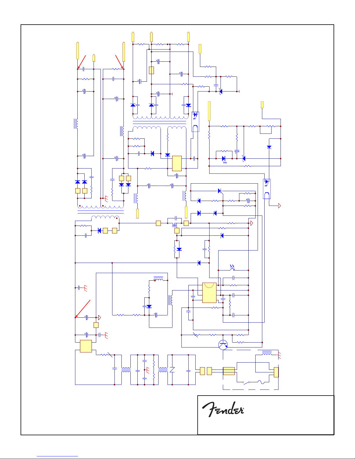
PASSPORT
SMPS Schematic Diagram
7

PASSPORT
SMPS PCB
8

+36V
Q204
R230
R241
U202
LM317HV
BD140
1
2
CN208
R237
4K7
R238
2K
CE
Z206
12V 1W
C205
47u/25V
68R/5W
100R/5W
C224
100n
3
Vin
Vout
2
R210
1K3 1%
ADJ
1
R209
240 1%
C223
10u/50V
CON2
Q203
9013H
C225
2u2/50V
B
R227
10K
R211
15K
D207
1N4148
START GROUND
CN201
WF2
PJ6-09- 3
PJ201
145
1
2
R SPKR OUT
TP10
PJ202 PJ6-09-3
START GROUND
145
SPKR OUT
+36V
L SPKR OUT
DGS
R219
3K3 2W
D205
1N4148
TP7
C217
100u/50V
C215
100n
Q208
2SK1058
C212
47u/25V
Z204
15V
TP9
C211
CN402
1
2
WF2
R228
-15V
TP5
CN209
LED201
2751-6
1
2
CN206
WF2
R240
1
2
1
2
LED PCB
100R/5W
R229
68R/5W
Z203
15V 1W
+15V
C221
47u/25V
C220
100n
R213
WF2
CON2
LED
209EGW
TP6
2K
R239
100R/5W
68R/5W
Z202
15V 1W
C222
47u/25V
C219
100n
1
2
WF2
CN205A
CN205
G
R
R204
THERMAL SWITCH
TH201
17AM203A5-4
CON2
CN207
2
1
85C
Z201
33V
R203
39K
-15V
1K
R212
R201
39K
+15V
R202
C201
2u2/50V
+15V BOOTST RAP
39K
Q201
MPSA06
D201
1N4148
2M2
224
D204
1N4148
D
G
Q207
J112
S
R226
R225
390
15K
1
R232
1K5
_
2
R231
5K1 1%
-36V
123
4
CN202
WF4
EXIT/DC
10A
F202
10A
F201
123
4
CN203
WF4
TP8
(OPTION)
-36V
C218
100u/50V
C216
100n
Q205
2SJ162
S
D
G
C214
R215
7
R216
390K
4 8
_
+
U203
BA4560
5
6
223
C210
R217
3M3
R218
1M
C209
1u/50V
D202
1N4148
D203
1N4148
R222
56K
R235
3R3 2W
R234
1K5
U203
BA4560
+
3
C206
22u/16V
VR201
NV26TLI 1K
1
S
G
R208
D
Q202
J112
-15V
39K
C203 47p
2
R205
10K
C202
1000pF
3M3
R221
100K
R224
390
220n
C208
47p
C207
4K7
R233
U201A
TL072
+15V
3
390
R207
R206
100K
1u/50V
TP4
R214
3K3 2W
47u/25V
D206
C213
1N4148
Z205
15V
HI-PA AGND
-15V BOO T STRAP
R220
1M
R223
15K
R236
3R3 2W
LO-PA GND
123
CN204
WF3
AUDIO IN
PASSPORT
AMP Schematic Diagram
9

Amplifier PCB Component Side
Amplifier PCB Copper Side
LED PCB Component Side
LED PCB Copper Side
PASSPORT
Amplifier / LED PCB
10

TP1 DC300V
TP2 DC34V
TP3 DC-34V
TP4
TP5 DC-15V
TP6 DC15V
TP7 DC34V
TP8 DC-34V
TP9 DC8V
PASSPORT
Test Point Information
11

TP10
TP11
PASSPORT
Test Point Information
12

TP12
TP13
PASSPORT
Test Point Information
13

TP14
TP15
PASSPORT
Test Point Information
14

TP16
TP17 DC8V
TP18 DC5V
TP19
PASSPORT
Test Point Information
15

TP20
PASSPORT
Test Point Information
16

SMPS PCB
AF_CH1
GND
GND
GND
AF_CH2
P-80 Wiring Diagram
RCA/XLR Input PCB
AUT_CH1
GND
white
GND
AUT_CH2
black
red
balck
Mixer PCB
CN7
CN605B CN604B
CN1
CN6
CN2
CN5
AMP PCB
CN209
VCC
CN203
CN402A CN208
CN201
CN205A CN205
CN204CN206
FAN
LED PCB
Reverb PCB
CN401
CN402
PASSPORT
Wiring Diagram
17

The following shows the legend of the mating connections
P-80 Wiring Diagram
CN604B
CN605B
CN205A CN205
PCB-P8011+MIXE PCB-P8011+RCA
1 GND 1 GND
2 MIC1+ 2 MIC1+
3 MIC1- 3 MIC14 MIC2+ 4 MIC2+
5 MIC2- 5 MIC26 OPEN 6 OPEN
7 OPEN 7 OPEN
8 OPEN 8 OPEN
9 OPEN 9 OPEN
10 RCA IN2 10 RCA IN2
11 STEREO R 11 STEREO R
12 STEREO L 12 STEREO L
13 TAPE OUT R 13 TAPE OUT R
14 TAPE OUT L 14 TAPE OUT L
15 GND 15 GND
PCB-P8011+MIXE PCB-P8011+DREV
1 -15V 1 -15V
2 AGND 2 AGND
3 +15V 3 +15V
4 AUDIO IN 4 AUDIO IN
5 AGND 5 AGND
6 AUDIO OUT 6 AUDIO OUT
PCB-P8011+MIXE PCB-P8011+PWRM
1 AUDIO OUT 1 AUDIO IN
2 GND 2 GND
3 OPEN 3 OPEN
PCB-P8011+MIXE PCB-P8011+PWRM
CN6 CN209
CN7
CN406
CN201
CN402 CN402A
2 -15V 2 -15V
1 +15V 1 +15V
PCB-P8011+MIXE PCB-P8011+SMPS
1 GND 1 GND
2 GND 2 GND
PCB-P8011+MIXE WIRELESS PCB
1 AF_CH1 3 AF_CH1
2 GND 4 GND
PCB-P8011+MIXE WIRELESS PCB
1 AF_CH2 8 AF_CH2
2 GND 7 GND
PCB-P8011+PWAM PCB-P8011+LED
2 GND 2 GND
1 +15V 1 +15V
PCB-P8011+PWAM WIRELESS PCB
2 +8V 6 +8V
1 GND 5 GND
PCB-P8011+PWRM PCB-P8011+SMPS
1 GND 1 GND
2 GND 2 GND
PCB-P8011+PWRM PCB-P8011+SMPS
1 +34V 1 +34V
2 GND 2 GND
3 GND 3 GND
4 -34V 4 -34V
PCB-P8011+DREV PCB-P8011+PWAM
2 +8V 2 +8V
1 GND 1 GND
CN1CN1
CN401CN2
CN204CN5
CN203CN203
PASSPORT
Wiring Diagram
18

2
5
3
No. DESCRIPTION PART NUMBER QTY
1 LATCH ARM 4153-2730+0 1
2 LATCH BRACKET 4133-9540+0 1
3 LATCH “C” PINS 4133-9430+0 2
4
4 LATCH SPRING 4133-9550+0 1
5 LATCH SAFETY CATCH 4153-2740+1 1
Remark:
Each unit contains 4 latch assemblies.
1
3
LATCH ASSEMBLY EXPLODED VIEW
No. DESCRIPTION PART NUMBER QTY
1 REAR PANEL P-80 4133-946D+0 1
2 AUX POWER CON BRACKET 4133-9510+0 1
3 GM FUSE HOLDER HOUSING 4153-1160+0 1
4 AUX POWER CONNECTOR 7010-0140+0 1
5 2.6x6 MM SCREW TF 2934-2606+3000 2
6 FUSE COVER P-80 4135-5511+0 1
7 POWER AMP HEAT SINK 5400-1881+1 1
8 MOUNTING BRACKET 4133-9490+0 2
9 POWER AMP PCB ASSEMBLY
P-80
10 BRASS TUBE STANDOFF 4133-9580+0 2
11 THERMAL MOUNTING
BRACKET
12 3x12MM SCREW PHPS 2944-3008+3000 9
13 SMPSU MODULE P-80 1
14 M3 METAL WASHER 2600-3005+0803 4
15 3x6MM SCREW PHPS 2944-3006+3000 11
16 M3 METAL SPRING WASHER 2607-3009+0553 12
17 3x8MM SCREW PHPS 2954-3008+3000 4
PCB-P8011+PWRM 1
4133-9090+0 1
POWER MODULE ASSEMBLY EXPLODED VIEW
PASSPORT
Latch Exploded View
19

No. DESCRIPTION PART NUMBER QTY
1 FRONT PANEL OVERLAY P-80 4155-0141+0 1
2 FRONT PANEL P-80 1466-7601+0 1
3 SHIELD PLATE 4133-9550+0 1
4 MIXER PCB ASSEMBLY P-80 PCB-P8011+MIXER 1
5 REVERB PCB ASSEMBLY P-80 PCB-p8011+DREV 1
6 RCA/XLR PCB ASSEMBLY 1723-080A+0000 1
7 XLR MIC JACK (RCA/XLR ASSY) 2113-1223+0 2
8 MIC JACK BRACKET (RCA/XLR) 4133-9570+0 1
9 SWITCH COVER 3100-4531+0 3
10 3X8MM SCREW TF 2954-3008+3000 14
11 M3 FIBER WASHER 2601-3008+0801 2
12 PCB STANDOFF 4153-1220+0 4
13 MIXER CONTROL KNOB 4153-2830+1 13
14 MASTER CONTROL KNOB 4153-2820+1 1
15 LED PCB ASSEMBLY PCB-P150D11+LED 1
16 3X8MM SCREW PHPS 2944-3008+3000 6
17 “U” BAR P-80 4153-2983+0 2
18/19 M3 METAL WASHER 2600-3003+0402 8
20 M12 HEX T-NUT 4133-9660+0 7
21 M13 METAL WASHER
4133-9650+0 7
MIXER ASSEMBLY EXPLODED VIEW
PASSPORT
Mixer Exploded View
20

4
5
6
3
2
10
9
1
11
3
10
10
12
13
14
10
7
11
8
SPEAKER ASSEMBLY EXPLODED VIEW
No. DESCRIPTION PART NUMBER QTY
1 BAFFLE GASKET 4153-2880+0 1
2 SPEAKER GRILLE 4133-9440+0 1
3 6.5” SPEAKER DRIVE UNIT 1525-1150+0 2
4 SPEAKER BOX 4153-3022+1 1
5 RED SPRUE CAP 4153-2902+0 1
6 NATURAL SPRUE CAP 4153-2810+0 1
7 SPEAKER STAND PLUG 1463-9100+1 1
8 6X25MM SCREW TF 2904-6025+3000 4
9 4x14mm SCREW PHPS 2954-4014+3000 1
10 4x10mm SCREW TF 2954-4010+3000 8
11 3X10MM SCREW FLAT HEAD 2951-3010+3000 2
12 M12 WASHER 4133-2810+0 1
13 12MM HEX NUT 4133-2820+0 1
14 SPEAKER STAND “O” RING 4152-2091+0 1
EACH UNIT CONTAINS TWO SPEAKER ASSEMBLIES.
PASSPORT
Speaker Exploded View
21

TOWER HOUSING ASSEMBLY EXPLODED VIEW
No. DESCRIPTION PART NUMBER QTY
1 TOWER SIDE CABINET 4153-2703+0 2
2 MIXER MODULE ASSEMBLY P-80 1
3 POWER MODULE ASSEMBLY P-80 1
4 SIDE PLATE(B) 4133-9480+1 1
5 HANDLE COVER 4153-2694+0 1
6 PARTITION 413-9450+3 1
7 COMPARTMENT DOOR 4153-2750-1 1
8 DOOR LATCH 4153-2760+0 1
9 3X8MM TF SCREW 2954-3008+3000 4
10 DOOR HINGE 4153-2780+0 2
11 COMPRESSION SPRING 4133-9560+0 1
12 FOOT STAND 4153-2714+0 2
13 SUPPORT RIB 4153-2724+0 1
14 HANDLE BRACKET 4133-9520+1 2
15 TOP GASKET 4153-2860+1 1
16 HANDLE GASKET 4153-2850+1 1
17 BOTTOM GASKET 4153-2870+1 1
18 SPEAKER LATCH ASSEMBLY SS-P15011+LALK 4
No. DESCRIPTION PART NUMBER QTY
19 M2.6x8 MM SCREW PHPS 2944-2608+0000 8
20 4X10 MM SCREW TF 2954-4010+3000 8
21 4X14 MM SCREW TF 2954-4014+3000 6
22 3X6 MM FLAT HEAD SCREW 2901-3005+3000 2
23 2.6X6 MM SCREW TF 2934-2606+3000 2
24 3X8 MM SCREW PHPS 2944-3008+3000 9
25 3X6 MM SCREW PHPS 2944-3006+3000 12
26 SIDE PLATE (A) 4133-9470+1 1
27 M3 METAL FLAT WASHER 2600-3005+0803 10
28 LOGO NAME PLATE 4153-2842+0 2
29 SPRUE CAP (GRAY) 4153-2810+0 2
30 4x16 MM SCREW TF 2910-4016+3000 2
31 4X16 MM SCREW PHPS 2940-4016+3000 8
32 M4 METAL SPRING WASHER 2607-4008+0653 8
33 M4 METAL WASHER 2600-4008+1003 8
34 M3 METAL SPRING WASHER 2607-3009+0553 3
35 HALO BUSHING 0813C 2113+9535+0 1
PASSPORT
Tower Housing Exploded View
22

No. DESCRIPTION PART NUMBER QTY
1 GIFT BOX P-80 1434-2103+0-3 1
8
2 MAIN UNIT POLY BAG 1497-2542+0 1
3 PADDED SIDE CARTON LINER 1434-2300+2-2 2
4 INNER SPACER BRACE 1434-4300+0-1 4
5 PE FOAM 1493-0641+0 2
6 WIRES POLY BAG 1497-2092+0 2
7 MAIN UNIT P-80 1
8 PADDED LINER 1434-2200+0-1 2
9 PE FOAM (TOP LINER) 1493-0631+0 1
10 9M SPEAKER CABLE 7010-0000+0 2
11 MAINS POWER CABLE REGIONAL 7011-6210+0 1
12 OWNER’S MANUAL P-80 4301-7169+1 1
13 PE FOAM (BOTTOM LINER)
1493-0651+0 1
6
UL
11
6
9
12
4
4
3
2
10
10
5
7
5
4
4
3
8
13
1
PACKING ASSEMBLY EXPLODED VIEW
23
PASSPORT
Packing Exploded View
 Loading...