

Page 1
111111110000XXXXPPPP,,,, 111111112222XXXXPPPP,,,, 111111115555XXXXPP
PP
IIIINN
NNSSSSTTTTRRRRUUUUCCCCTTTTIIII
OO
OO
NN
NN
MM
MMAAAA
NN
NNUUUUAAAALLLL
111111110000XXXXPP
PP
111111112222XXXXPPPP
111111115555XXXXPP
PP
XX
XX
PP
PP
AA
AA
RR
RR
TT
TTIIII
SS
SS
TT
TT
SS
SS
EE
EE
RR
RRIIII
EE
EE
SS
SS
LL
LL
OO
OO
UU
UU
DD
DD
SS
SS
PP
PP
EE
EE
AA
AA
KK
KK
EE
EE
RR
RR
SS
SS
YY
YY
SS
SS
TT
TT
EE
EE
MM
MM
SS
SS
Page 2
wwwwww..ffeennddeerr..ccoomm
2
wwwwww..mmrrggeeaarrhheeaadd..nneett
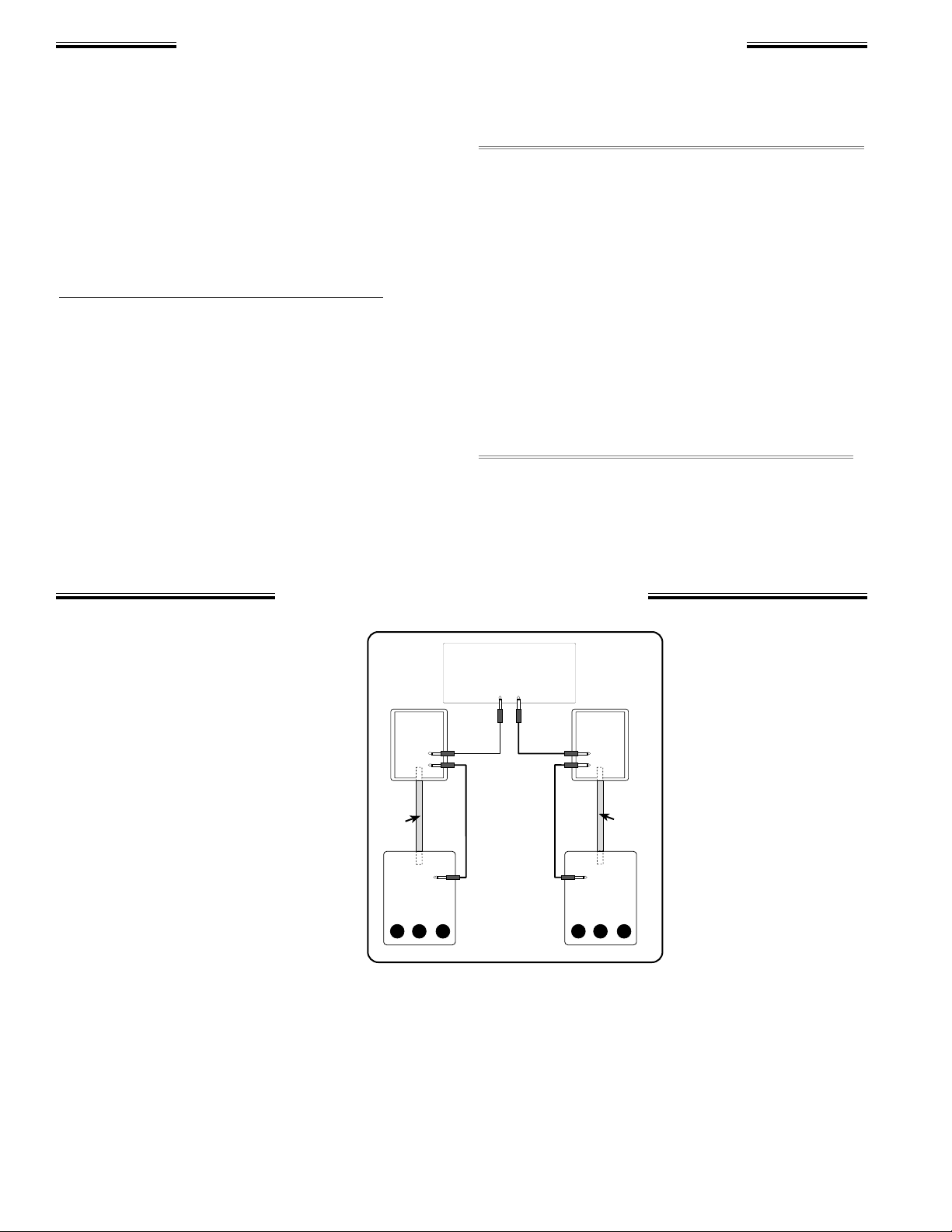
Each XP Series Loudspeaker cabinet
is equipped with two 1/4" jacks.
These standard phone jacks are wired
in parallel, allowing either one to be
used as the input; the other jack can
then be used as output to an additional speaker cabinet in a "daisy-chain"
connection scheme. Fig. A illustrates
the XP system “daisy-chained” with
Fender 115sA or 118sA Sub-woofers.
Avoid damage to your equipment by
ensuring that the total speaker
impedance load is within the limits set
by the amplifier’s manufacturer.
XP Series Speakers have an
impedance of 8Ω. Listed below are the combined
impedance loads of the XP Series loudspeaker
connected in parallel with speakers of 4Ω, 8Ω and
16Ω ratings:
• XP Series 8Ω + any 4Ω speaker = 2.6Ω load total
• XP Series 8Ω + any 8Ω speaker = 4Ω load total
• XP Series 8Ω + any 16Ω speaker = 5.3Ω load total
Using the recommended speaker impedance
load ensures optimum
efficiency and signal
response. The total
impedance load of a
“daisy-chain” scheme
can be adjusted by
using speakers of different impedances. One of
the results of mixing
speaker impedances
though, is that any
speakers with lower
impedance ratings will
have a higher power
consumption and output. For example, the power
use/output of a 2Ω speaker will be twice that of a
4Ω speaker and 4 times that of a 8Ω speaker.
Consider this when positioning speakers linked in a
“daisy-chain.”
FFFFeeeennnnddddeeeerr
rr
®®
®®
XXXXPPPP LLLLoooouuuuddddssssppppeeeeaaaakkkkeeeerrrr SSSSyyyysssstttteeeemmmmssss
SSSSppppeeeeaaaakkkkeeeerrrr CCCCoooonnnnnnnneeeeccccttttiiiioooonnnnss
ss
The Fender® 110XP, 112XP, and 115XP two-way,
professional quality loudspeaker systems are
designed to form the basis of everything from a
public address system permanently installed, to
the nightly rigors of a working band’s portable
sound system. Add ultra-deep bass to the your XP
Series Loudspeaker System with a Fender 115sA
or 118sA Subwoofer Loudspeaker System.
Features of XP Artist Series Loudspeakers:
• Great fidelity using a trapezoidal cabinet design
• Moisture sealed 5/8” particle board cabinet
• Pole-mount sockets
• Two high-current, 1/4” phone jacks to enable
“daisy-chain” cabinet linking
• Dual piezoelectric compression drivers
• Silver grill cloth
• Metal corner protectors and glide feet
• Genuine Tolex® cabinet covering
• Compact and portable
• CAUTION: Speakers produce magnetic fields
which may interfere with the operation of nearby electronic devices such as televisions and
computers. Increase the distance between
speakers and electronic devices to reduce interference.
• WARNING: Fender loudspeaker systems are
capable of producing very high sound pressure
levels which may cause temporary or permanent hearing damage. Use care when setting
and adjusting volume levels during use..
• No user serviceable part inside, refer servicing
to qualified personnel only.
XP
Series
XP
Series
115sA/
118sA
115sA/
118sA
Fender
Pole
Mount
Fender
Pole
Mount
Powered
Mixer
TYPICAL
“DAISY-CHAIN”
SCHEME
FIG. A
Page 3

wwwwww..ffeennddeerr..ccoomm
3
wwwwww..mmrrggeeaarrhheeaadd..nneett
There are several things to
consider when placing loudspeaker cabinets. First
determine the horizontal
coverage requirements for
the room. When used in a
typical auditorium setting,
position the speakers as
shown in Fig. B. Ensure
adequate sound levels reach
each seat in the audience by
walking through the entire
auditorium—listen for any
gaps in coverage then reposition speakers as necessary. Recheck sound coverage with a full audience in attendance, if possible.
The XP Series horn has a horizontal coverage
angle of 70º and a vertical coverage of 35º; bass
speakers are nearly
omnidirectional.
When setting up
your XP Series
enclosures as a
“single unit,” aim
the cabinets 70°
apart as shown in
FIG. C, for 140°
of horizontal coverage.
Other considerations include
bass frequency
performance and
feedback...
When a XP
speaker is placed
near a wall, there
will a low-frequency boost of
up to 3dB. The
drawback is that
close proximity to
a wall may also cause feedback.
To avoid feedback: Increase the distance
between speakers and the feedback source
whether it is a wall, a microphone, or a guitar. Use
cardioid–pattern microphones to help block feed-
back. Always keep microphones
pointed away from speakers.
Sound quality is often compromised when a sound system is
required to be hidden from
sight. Remember that the
location of your loudspeaker
cabinets will affect sound qual-
ity and coverage area more than
any other factor.
Power and audio signal cables are a
common sources of sound system failure. Quality cables, carefully maintained,
are essential to the reliability of the entire
sound system. Long cable connections
or cables supplying multiple speaker
cabinets must be of a sufficient gauge to
transfer all of the available amplifier
power to the speakers. As a rule, thicker cables (lower gauge numbers) are
more efficient because they absorb less
power themselves.
Prevent power loss and the degradation of signal quality by
using the recommended cable gauges below.
Cable that suppplys one cabinet, such as the cable to the last
cabinet in a “daisy-chain”:
• Up to 50-feet requires 18-gauge cable
• Up to 100-feet requires 16-gauge cable
Cable that suppplys two cabinets, such as the cable from the
amp to the first cabinet in a “daisy-chain”:
• Up to 25-feet requires 18-gauge cable
• Up to 50-feet requires 16-gauge cable
• Up to 100-feet requires 14-gauge cable
SSSSppppeeeeaaaakkkkeeeerrrr CCCCaaaabbbblllleeeessss
AAAAccccoooouuuussssttttiiiiccccssss aaaannnndddd CCCCaaaabbbbiiiinnnneeeetttt PPPPllllaaaacccceeeemmmmeeeennnntttt
Stage
70°
70°
Audience
FIG. B
XP
XP
1
4
0
˚
o
f
H
o
r
i
z
o
n
t
a
l
C
o
v
e
r
a
g
e
70°
FIG. C
XP
XP
Page 4

MODEL: 110XP 112XP 115XP
PART NUMBER: 071-1100-400 071-1200-400 071-1500-400
MAXIMUM OUTPUT: 117dB Continuous 118dB Continuous 120 dB Continuous
(at 1 Meter) 123dB Peak 124dB Peak 126dB Peak
CABINET: 5/8" (1.6 cm) 5/8" (1.6 cm) 5/8" (1.6 cm)
Particle Board Particle Board Particle Board
CONNECTIONS: (2) 1/4" Phone Jacks (2) 1/4" Phone Jacks (2) 1/4" Phone Jacks
DRIVER: Low Frequency: 10" (25.4 cm) woofer 12" (30.5 cm) woofer 15" (38.1 cm) woofer
2" (5.1 cm) voice coil 2" (5.1 cm) voice coil 2.5" (6.4 cm) voice coil
High Frequency: Dual Piezoelectric Dual Piezoelectric Dual Piezoelectric
Compression Drivers Compression Drivers Compression Drivers
1 1/2" (3.8 cm) diaphragms 1 1/2" (3.8 cm) diaphragms 1 1/2" (3.8 cm) diaphragms
FREQUENCY RESPONSE: 65 Hz to 20kHz 60 Hz to 20kHz 60 Hz to 20kHz
SENSITIVITY: 1W/1m: 97 dB 98 dB 98 dB
POWER HANDLING: 100W (RS-426A) 100W (RS-426A) 150W (RS-426A)
200W (Program) 200W (Program) 300W (Program)
400W (Peak) 400W (Peak) 600W (Peak)
IMPEDANCE: 8Ω 8Ω 8Ω
DIMENSIONS: Height 20.3" (51.6 cm) 21.3" (54.1 cm) 23.9"(60.7 cm)
Width (front) 14.6" (37.1 cm) 18" (45.7 cm) 21" (53.3 cm)
Width (rear) 6.4" (16.3 cm) 6.4" (16.3 cm) 8.4" (21.3 cm)
Depth 15.6" (39.6 cm) 18.4" (46.7 cm) 19.6" (49.8 cm)
WEIGHT: 37 lbs. (16.8 kg) 50 lbs. (22.7 kg) 58 lbs. (26.4 kg)
A PRODUCT OF:
FENDER MUSICAL INSTRUMENTS CORP.
CORONA, CA USA
Fender® is registered trademark of FMIC
Tolex® is a registered trademark of GenCorp, Inc.
P/N 057245 REV A
XXXXPPPP SSSSeeeerrrriiiieeeessss SSSSppppeeeecccciiiiffffiiiiccccaaaattttiiiioooonnnnssss
 Loading...