

Femtochrome FR-103MN Instruction Manual
FEMTOCHROME. RESE A R C H , INC.
FR-103MN AUTOCORRELATOR
INSTRUCTION MANUAL
2123 4th Street Berkeley, California 94710 T el (510) 644-1869 Fax (510) 644-0118
o n nn il* to ^ h (3)fo n n t n ^ h rr% n n o r^r\m h t t r v / /uaaAa/ fomtnr^hrnmA r.nm
TABLE OF CONTENTS
L Introduction
...............................................
.
2. Theory of Operation
..................................
.
3. Operating Instructions
a. Fundamental Characteristics
...........
b- Alignment Procedure
......................
a Alignment H ints
..............................
cL Wavelength Dependence
.................
e. Wide Scan Range/Scan Nonlinearity
f- Input Beam Polarization
................
g. Pulsewidth Calibration
......
.............
h. Major Optics Alignment
.................
2
o 1 1 1 11
2
3
I
X
1
X
1
A
1
A
1
A 1
L
Options
a. Crosscorrelation (/CC)
..........................................
b. Interferometric Option (flO)
......................
c. Fiber Adapter (/FA)
...............................................
.
d Fiber Coupled (/FC)
...............................................
e- Low Rep Rate Option (/LRR)
................................
f. Computer Data Acquisition (/CDA)
..........
g - VGA Display Option (/VGA)
............................
h- Extended Wavelength (IR) Options (/1000, /2000)
Spare Parts List
................................................
...........
Warranty Information
The standard FR-103MN utilizes background-free (noncollinear) second harmonic generation
(SHG) for the measurement of the autocorrelation fimction of repetitive ultrashort laser pulses.
The unit can be set to crosscorrelate two synchronized pulses of different wavelengths.2
Collinear SHG (with background) with interferometric resolution is offered as an option(/IO),3
The Low Rep Rate Option4 (/LRR) renders the unit applicable for any rep rate (as low as 4Hz).
The optional Fiber Adapter (/FA) or (/FC) facilitate easy alignment and repeatable connection of
fiber coupled beams. An optional A/D board installed in the unit and its software (Computer
Data Acquisition (/CDA)),provides an interface (RS232) of the FR-103MN with a PC, resulting
in a complete pulsewidth monitoring system. Alternatively,the N GA option renders the unit
completely self-contained in a single package including a color TFT display.
1 For high resolution or best performance at a specific wavelength, a custom crystal
can be selected
2
3
See 3L Crosscorrelation,p. 14
See 4a. Interferometric Option, p. 16
See 4e. Low Rep Option, p.19
1. INTRODUCTION
The Model FR-103MN Rapid Scanning Autocorrelator is a high resolution instrument for
continuous monitoring and display of femtosecond and picosecond laser pulses. While its
unprecedented resolution makes it ideal for fsec pulses from modelocked lasers with high peak
power,the instrument’s high sensitivity renders it perfectly suited also for long pulses with low
power. The operation ranges of the FR-103MN can be interchangeably selected as follows1:
FR-103MN/BBO (410-900 nm): BBO crystal (0.3 mm/60°)/VS Beamsplitter/VS PMT
FR-103MN/KDP (530-1070 nin): BBO crystal (0.3 mm/35°)A^S Beamsplitter/VS PMT
FR-103MN/IR (700-1800 nm): LiI03 crystal (1 mm/24°)/IR Beamsplitter/IR PMT
Note: The wavelength range of410-1800nm can be further extended into the IR region
optionally, by photodiode detector modules /1000 (1000-2000nm) and /2000 (2000-3000nm).
These options utilize the same optics as in the /IR version.
An appropriate set of fundamental blocking filters is included for each operating range.
The unique scanning mechanism6 of the FR-103MN provides a dispersion free scan range of
>60 psec with high linearity. Dispersion is eliminated through the exclusive use of high reflecting
metallic coated mirrors,with a focus in the nonlinear (NL) crystal obtained by means of a curved
mirror. The pulsewidth resolution is <5 fsec using an ultrathin (<0.05 mm) crystal.
2. THEORY OF OPERATION
The FR-103MN utilizes the SHG method of the 1 st kind in the conventional Michel so n
Interferometer set-up of pulsewidth measurement.5 In the standard configuration, noncollinear
beams lead to the background-free autocorrelation measurement Repetitive linear delay
generation in one arm of the Michelson arrangement is introduced by a pair of parallel (//)
mirrors centered about a rotating axis.6 In the geometry of Figure 1 ,the rotation of the // mirror
assembly leads to an increase (or decrease) of path length for 汪 traversing beam.6 Thus,the
transmitted pulse train is delayed (or advanced) about the reference (zero delay) position. This
delay varies with time as a fixn c ti o n of the shaft’s rotation. For small angular changes, the delay
as a function of time is linear and given by6
T = { ^ . } t (1)
c v 1
where D is the distance between the // mirrors,f is the frequency of rotation,and c is the speed of
light.
Rotation of the // mirror assembly leads to a repetitive generation of linear delay which,used in
the described SHG configuration, provides a continuous display of the autocorrelation function
of the pulses on a conventional high impedance oscilloscope synchronized to this rotation.
5
6
E-P . Ippen and C,V. Shank, "Ultrashort Light Pulses/1 SX. Shapiro ed” New York:
Springer-Verlag (1977)
Yasa and R M Amer,Optics Commun” V36,406 (1981)
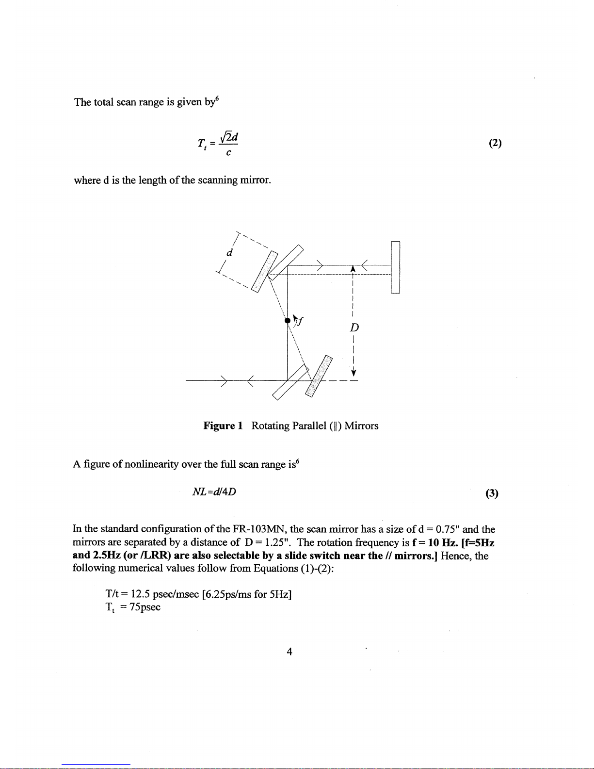
The total scan range is given by6
^2d
I — c
(2)
where d is the length of the scanning mirror.
Figure 1 Rotating Parallel (||) Mirrors
A figure of nonlinearity over the full scan range is6
NL=d/4D (3)
In the standard configuration of the FR-103MN,the scan mirror has a size of d = 0.75n and the
mirrors are separated by a distance of D = 1.25”. The rotation frequency is f = 10 Hz. [f=5Hz
and 2.5Hz (or /LRR) are also selectable by a slide switch near the // mirrors.】 Hence, the
following numerical values follow from Equations (1)_(2):
T/t = 12.5 psec/msec [6,25ps/ms for 5Hz]
Tt = 75psec
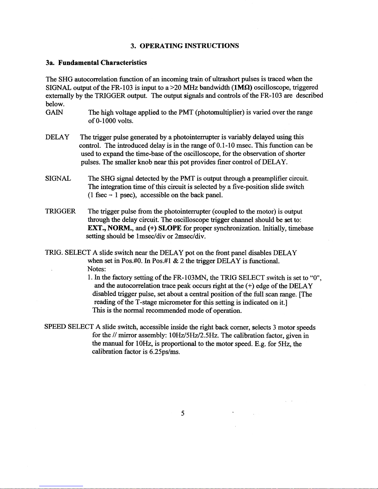
3- OPERATING INSTRUCTIONS
3a. Fundamental Characteristics
The SHG autocorrelation function of an incoming train of ultrashort pulses is traced when the
SIGNAL output of the FR-103 is input to a >20 MHz bandwidth (IM il) oscilloscope, triggered
externally by the TRIGGER output- The output signals and controls of the FR-103 are described
below.
GAIN The high voltage applied to the PMT (photomultiplier) is varied over the range
of 0-1000 volts.
DELAY The trigger pulse generated by a photointermpter is variably delayed using this
control. The introduced delay is in the range of 0.1-10 msec. This function can be
used to expand the time-base of the oscilloscope, for the observation of shorter
pulses. The smaller knob near this pot provides finer control of DELAY.
SIGNAL
The SHG signal detected by the PMT is output through a preamplifier circuit.
The integration time of this circuit is selected by a five-position slide switch
(1 fsec — 1 psec),accessible on the back panel.
TRIGGER The trigger pulse from the photointerrupter (coupled to the motor) is output
through the delay circuit. The oscilloscope trigger channel should be set to:
EXT” NORM., and (+) SLOPE for proper synchronization. Initially, timebase
setting should be lmsec/div or 2msec/div.
TRIG. SELECT A slide switch near the DELAY pot on the front panel disables DELAY
when set in Pos.#0. In Pos.#l & 2 the trigger DELAY is function al *
Notes:
1 • In the factory setting of the FR-103MN,the TRIG SELECT switch is set to “0
and the autocorrelation trace peak occurs right at the (+) edge of the DELAY
disabled trigger pulse,set about a central position of the full scan range. [The
reading of the T-stage micrometer for this setting is indicated on it.]
This is the normal recommended mode of operation.
SPEED SELECT A slide switch,accessible inside the right back comer, selects 3 motor speeds
for the // mirror assembly: 10Hz/5Hz/2.5Hz. The calibration factor,given in
the manual for 10Hz,is proportional to the motor speed. E.g. for 5Hz,the
calibration factor is 6.25ps/ms.
 Loading...