

Page 1
Operating instructions:
made in Germany
Femo
Inh. Felix Vogt
Unter Burghalde 90
71229 Leonberg
Phonel.: +49 (0)170-7316813
E-Mail: [email protected]
Page 2

Preface
We congratulate you and thank you for choosing a high-performance flight model from
Femo. Our flight models are manufactured in the `Prepreg-autoclave-technology` in
Germany. Both the strength values and the surface quality are unique. The completion of
the models relates only to the installation and connection of the receiver and the receiver
battery. The entire harness is already installed. In order to ensure safe use,
Please read this manual carefully.
Further information about our products and application or operating questions can be obtained from:
Contents
Assembly……….…................................................................................... 1
Motor Unit.................................................................................................. 2
Rudder Settings and Servos...................................................................... 3
Operation................................................................................................... 4
Cleaning and care...................................................................................... 5
Safety instructions
Check the device after unpacking. Do not use in case of transport damage. Report the damage in writing, otherwise the warranty claim
is void. The appliance must be used in accordance with the enclosed operating instructions.
Fire Hazard!
There is a risk of fire for lithium-ion batteries.
Danger of injury!
As soon as the drive is under current, there is a risk of injury due to sudden rotation of the propeller.
Warranty
We provide a 24-month warranty on this product. All other claims are excluded. This applies in particular to claims for damages caused
by failure or malfunction. We assume no liability for personal injury, damage to property and its consequences arising from our delivery
or work (except in case of gross negligence or intent), because we cannot control the handling and application.
Page 3
1. Assembly
________________________________________________________________________
The center of gravity is measured at the root rib, 60-70mm behind the nasal strip
and is predetermined with the motor-snout.
First, holes for the outputs of the receiver antenna/antennas must be installed.
The receiver is inserted into the wingunit. And should be mounted as far back as
possible to have enough space for the motor-snout plugs and cables.
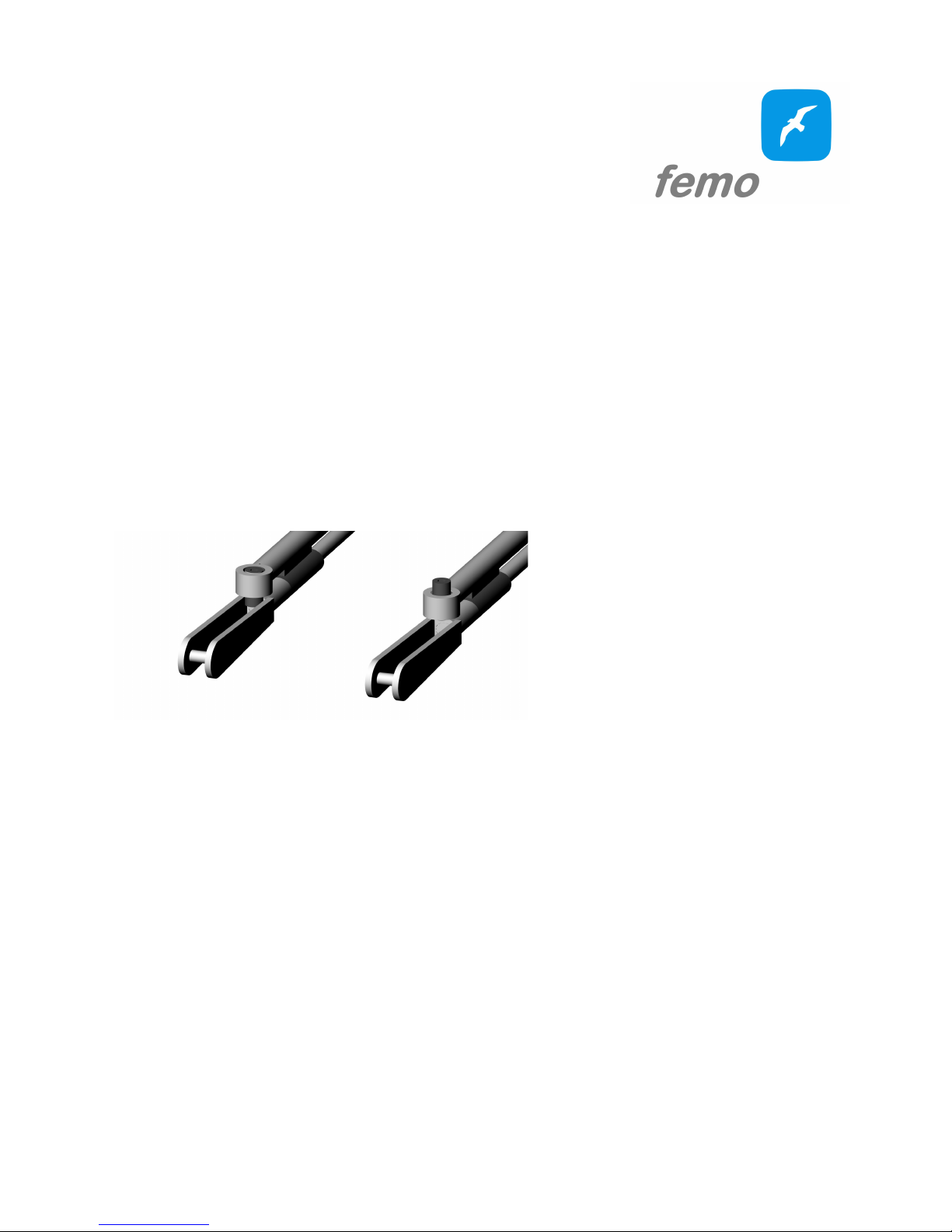
The semi-automatic rudder connections facilitate the connection of elevator and
rudder. When the fuselage is set, the rods are pushed onto the glass fibre rods. The
grub screw locks (Left image) when you turn it on or opens ( right image) when
turnig out. The technique requires some practice.
The Assembly before flying is carried out in the following way:
1. Put on the elevator wings.
2. Check that the grub screws of the rudder connections are open. Fix the rods
and push them with the fuselage.
3. By moving the elevator and rudder Manually push the linkage to the stop
and use the grub screw to lock.
4. Fix the fuselage screw (do not tighten) check the correct position of the tail
section by looking over the main wing section, then tighten the screw.
5. Connect the nose, attach it and screw it tightly.
Page 4

2. Motor Unit
________________________________________________________________________
The e-nose has the following components installed.
- Hacker A20 XL
- Speed Controller YEP 30Ah
- Nanotech Lipo 1000mAh 11.1V max.40C
- Aeoronaut Cam Carbon 8x7''
- Femo `Versatzmitnehmer and Spinner`
Please observe the operating and maintenance instructions of the respective manufacturer.
The speed controller with BEC is already programmed.
Before inserting the Lipo, hold the receiver cable in the flight direction above and
insert the Lipo, then plug it in and fully push it up to the light stop. Do not push the
receiver cable. Only when the lipo is in the correct position can the nose be easily
and without any effort.
The Apus is ideal for the `Flitschen`. If necessary, the `Flitschen`-hook is screwed
into the thread in the front part of the glider's nose. Tighten the screwing of the nose
and tail tightly. Now the Apus can be raised on the rubber. The start is with ailerons
on speed position. At the first start-up attempts should be started with a slightly
drawn elevator.
Page 5

3. Rudder Settings and Servos
________________________________________________________________________
All servos are already installed in Femo flight models. The main wing rudders are
guided by RDS systems. The entire deflection is inside. In case of a servo damage
this can be exchanged via a prepared servo cover!
Please reduce the servo at your control first, then set the middle position. Then
raise the servo again to get the necessary rudder swings. In order not to burden the
servo unnecessarily, we recommend to prevent servo movements starting from the
rudder during transport and storage. Our area scissors are ideal for this purpose.
In the current versions, KSTX08 v 3.0 is installed these servos can be directly
be operated with 2s lipos.
When using the e-nose and the nose of the glider, it is advisable to create two
model memories. Since the centre of gravity is not 100% identical due to the nasal
change.
Settings
+ means "flap/rudder Down"
- means "flap/rudder up"
ELEV = Elevator
AILE = Aileron
RUDD = Rudder
Rashes max.:
AILE: -12/+6 (measured outside)
ELEV: -5/+5
RUDD: -12/+12
ELEV neutral: parallel to the hull
Speed:
AILE: -1,5mm
Snapflap AILE: +2,5mm
Thermal:
AILE:+1,5mm
Landing configuration:
QRAILÖE: -12mm
ELEV: -2mm
Page 6

4. Operation:
________________________________________________________________________
The flight model is to be operated on a suitable flight ground. In order to ensure safe
operation, pre-flight inspection is to be carried out before each flight.
The following points should be checked and fulfilled:
1. Correct assembly.
2. Fixed seat of all components.
3. All rudders are free-of-charge.
4. Correct model memory and rudder occupancy.
5. Correct center of gravity.
6. Power supply sufficient.
5. Cleaning and care:
________________________________________________________________________
In order not to damage the surfaces, aggressive detergents such as acetone should
not be used. Alcohol or commercial vehicle paint cleaning and care products are
suitable. The carbon fiber surface is temperature insensitive to 90 °c, however it is
recommended to protect the model from direct sunlight as the model can heat up
very strongly and the electronics can get damaged.
 Loading...