

Fema Electronica S40-R, S40 Series User Manual
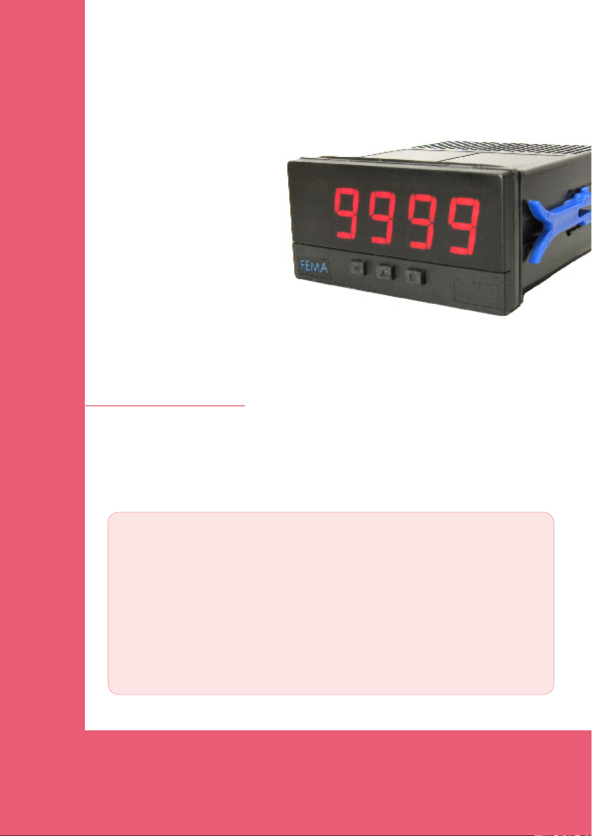
Panel Meters
Series S40
Panel meter 72x36mm
Model S40-R
for Ratiometric signals
for Potentiometers up to 5M
Panel meter for ratiometric and potentiometer signals. Accepts 3 wire ratiometric
signals. Accepts potentiometers up to 5 MOhm and from 200 Ohm
reduced housing size with standard 14mm digit height. excitation voltage for
transducers. Includes “measure” function (signal input visualization), peak&hold,
double setpoint alarms, brightness control, lters, ... Universal power options in
AC and DC, signal retransmission and control options (relay outputs, analogue
outputs, ...).
. Instrument with
FEMA ELECTRÓNICA
USER’S MANUAL
(2704R00)
User’s Manual S40-R
Meter S40-R
Panel meter 72x36mm for ratiometric and potentiometer signals
Panel meter for ratiometric and potentiometer signals, from 3
wire transducers. The meter provides +5V (max. 35mA) and
a 0V signal, and receives from the transducer a signal between 0 and 5V. Scalable reading. 10 segment linearization
Reduced size 72x36mm DIN standard instrument, maintains
standard 14mm digit height, with full 4 digit resolution plus
additional negative sign.
Management for up to 2 alarms with 1 or 2 setpoints each,
with hysteresis and delays. Functions available include segment linearization, memory of maximum and minimum, left
zeros, steps on display, xed digits, recursive display lter,
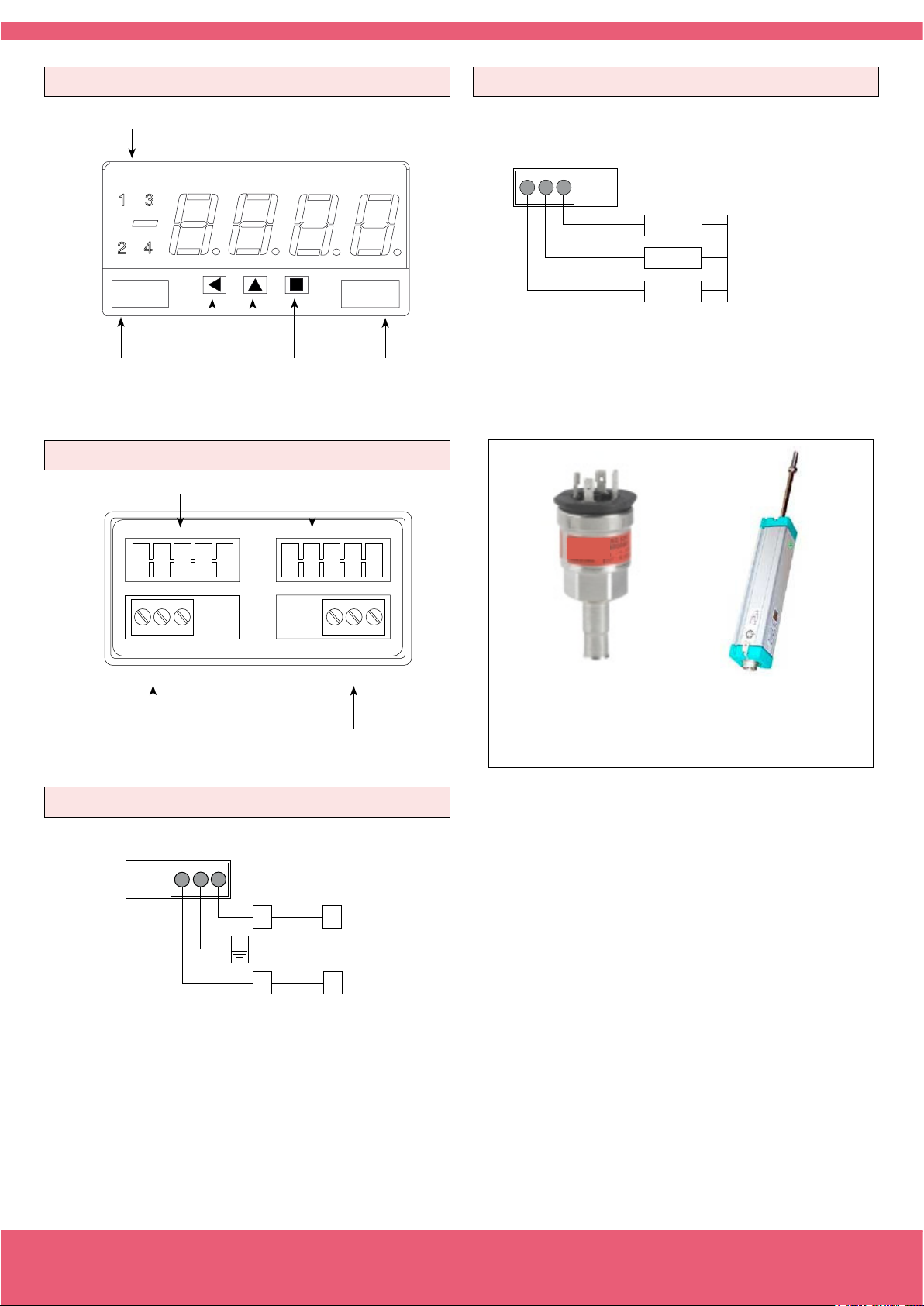
Order Reference
S40
Model
-
R
- - ---
Power
H
(85-265 Vac/dc)
-H
-L (11-60 Vdc
and 24/48 Vac)
password, brightness control, function “measure” for visualization of input signal without scaling, offset and signal high
autocorrection and “peak&hold” function.
Power options in AC and DC with universal range power
modules, and space for two additional control and/or retransmission modules. .
Standard IP54 front protection, with optional upgrade to IP65
protection.
Connections via plug-in screw terminals and conguration
via three front push-buttons. For application on industrial
environments.
Option1
(1 relay)
-R1
-AO (Analogue Output)
-(empty)
Option2
-
-R1
---
(1 relay)
-AO (Analogue Output)
-(empty)
-
Others
---
(IP65)
-65
-(empty)
Precautions on installation
Risk of electrical shock. Instrument terminals can be connected
to dangerous voltage.
Instrument protected with double isolation. No earth connection
required.
Instrument is in conformity with CE rules and regulations. See
“CE Declaration of Conformity” further in this document.
This instrument has been designed and veried according to the 61010-1
CE security regulation, and is designed for applications on industrial environments. See the “CE Declaration of Conformity” further in this document for
information on the category of measure and the degree of pollution levels
that apply.
Installation of this instrument must be performed by qualied personnel
only. This manual contains the appropriate information for the installation.
Using the instrument in ways not specied by the manufacturer may lead
to a reduction on the specied protection level. Disconnect the instrument
from power before starting any maintenance and / or installation action.
FEMA ELECTRÓNICA - Page 2
The instrument does not have a general switch and will start operation as
soon as power is connected. The instrument does not have protection fuse,
the fuse must be added during installation.
The instrument is designed to be panel mounted. An appropriate ventilation
of the instrument must be assured. Do not expose the instrument to excess
of humidity. Maintain clean by using a humid rag and do NOT use abrasive
products such as alcohols, solvents, etc.
General recommendations for electrical installations apply, and for proper
functionality we recommend : if possible, install the instrument far from
electrical noise or magnetic eld generators such as power relays, electrical motors, speed variators, ... If possible, do not install along the same
conduits power cables (power, motor controllers, electrovalves, ...) together
with signal and/or control cables.
Before proceeding to the power connection, verify that the voltage level
available matches the power levels indicated in the label on the instrument.
In case of re, disconnect the instrument from the power line, re alarm
according to local rules, disconnect the air conditioning, attack re with
carbonic snow, never with water.
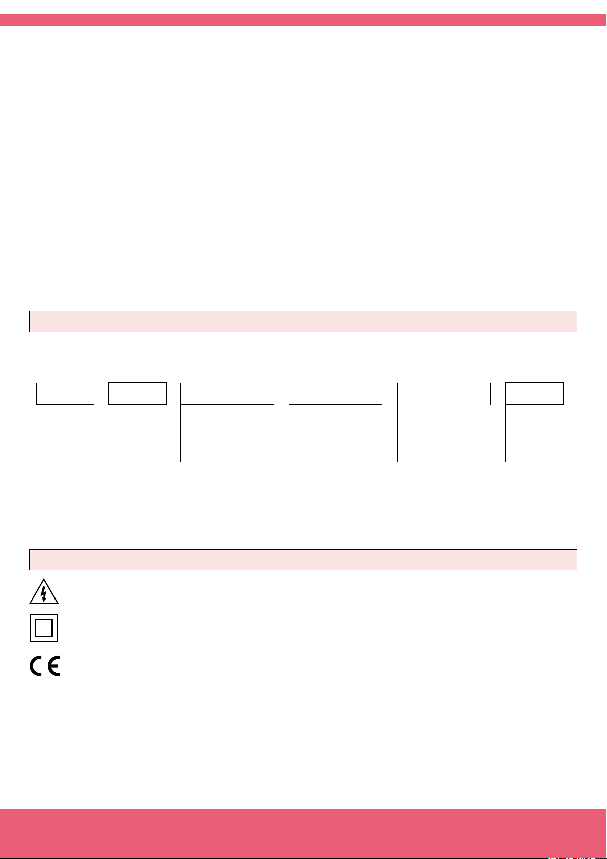
Alarms
Front View
Signal Connections
123
Logo
Button
LE
Button
UP
Button
SQ
Rear View
Option1 Option2
Units
Vexc +5V
Signal
Common
Ratiometric transducer
or potentiometer
3 wires
PowerSignal
Power Connections
67890
~
~
Earth connection - Although a terminal is offered for earth connection, the
connection is optional. The instrument does not need this connection for
correct functioning nor for compliance with the security regulations.
Fuse - To comply with security regulation 61010-1, add to the power line
a protection fuse acting as disconnection element, easily accessible to the
operator and identied as a protection device.
Power “H” fuse 250mA time-lag
Power “L” fuse 400mA time-lag
+
-
Example of ratiometric
transducer for pressure.
Example of ratiometric
transducer for length.
FEMA ELECTRÓNICA - Page 3
User’s Manual S40-R
Technical Data
Digits 4
Type 7 segments, red
Height 14 mm
Display maximum 9999
Display minimum -1999
Decimal point selectable 8.8.8.8.
Overrange 9999 ashing
Underrange -1999 ashing
Signals accepted Ratiometric, potentiometers
Ratiometric 3 wire ratiometric sensors
Potentiometers Pots from 200 Ohm up to 5 MOhm
The instrument provides two ranges for potentiometer measurement. In Pot<5K measurement range, the measure is
direct (no additional conguration is needed). In Pot<5M it
is needed to introduce the nominal value of the potentiometer to reach the assigned accuracy. This value is requested
when the Pot<5M is selected.
Connections 3 wires
Input impedance 932K
Oversignal max. 100Vdc
Excitation voltage
Voltage output +5Vdc
Max. current 35mA
Protection against short-circuit
Technical Data (cont.)
Peak & Hold yes
Double setpoints yes
Brightness control yes, 5 levels
Thermal stability
offset 10 ppm/ºC
span* 35 ppm/ºC
*span drift includes the offset drift
Options maximum 2
Mechanical
Mounting panel
Connections plug-in screw terminals
Weight <150 grams
Housing materials ABS, polycarbonate, vergaex
Front size 72x36mm
Panel cut-out 69x32.5mm
Deep from panel 98mm (including terminal)
Protection IP54 standard
IP65 optional (sealed front lter.
Opening the housing breaks the
seal)
Temperature Operation 0 to 50ºC
Temperature Storage –20 to +70ºC
Warm-up 15 minutes
Accuracy at 25ºC
200R < Pot < 5Mohm 0.15% F.S. ±1 digit
Pot > 5MOhm 0.15% F.S. ±1 digit
Ratiometric 0.15% F.S. ±1 digit
Acquisitions 5 acquisitions / second
Display refresh 5 display refresh / second
Step response time <200mSec (0% to 99% signal)
Power
Power “H” 85 to 265 Vac/dc
Power “L” 11 to 60 Vdc and 24/48Vac
Consumption <4W
Isolation 3500Veff for power “H”
2000Veff for power “L”
all levels tested for 60 seconds
Conguration 3 frontal push buttons
Functions available
Segment linearization 10 segments
Fixed digits yes, congurable
Filter on display yes, recursive, congurable
Steps yes, congurable
Memory of maximum yes
Memory of minimum yes
Zeros to the left yes, congurable
Password yes, congurable
“Measure” function yes
Auto correction high yes
Auto correction low yes
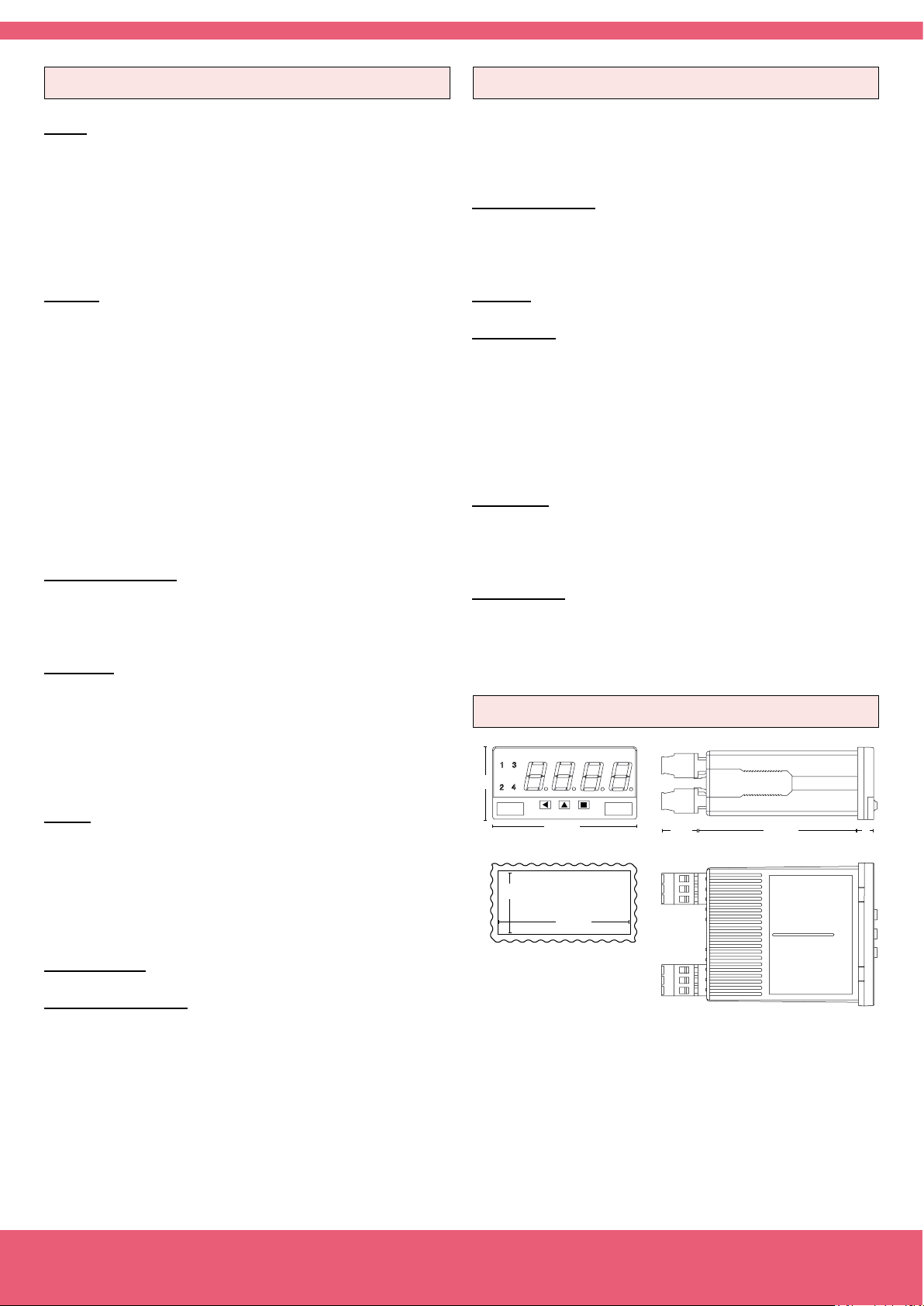
Mechanical Dimensions (mm)
36
32,5
72
Panel
cut-out
69
18
80
8
FEMA ELECTRÓNICA - Page 4
 Loading...