


® U.S Registered Trademark
Copyright © 2007 Honeywell Inc. • All Rights Reserved MU2B-0328GE51 R0207A
Smart DCM/SN
ELECTRONIC PRESSURE SWITCHES AND TRANSMITTERS
OPERATING INSTRUCTIONS
GENERAL
Honeywell FEMA's Smart DCM Electronic Pressure Switches
and Smart SN Electronic Pressure Transmitters are microprocessor-controlled pressure measurement devices for
relative pressure measurements (-1…+1 bar / 0…40 bar).
With their high-performance stainless steel sensor material,
they are suitable for a wide range of liquid media or gases in
industrial applications. They are screwed (G1/2”) directly into
the line / vessel to be monitored.
BEFORE PROCEEDING!
VALIDITY
These Operating Instructions pertain to measuring systems
containing Smart SN Pressure Transmitters / DCM Pressure
Switches. Device software must be version 1.30 or higher.
QUALIFIED PERSONNEL AND USAGE
Use only these Operating Instructions (and the corresponding
Mounting Instructions) to set up and operate the device. Only
qualified personnel are permitted to install, commission,
operate, and maintain the device. This device may be used
only in applications and under operating conditions described
in these Operating Instructions.
TECHNICAL DATA
Materials
Parts contacting medium Stainless steel (1.4571)
Chemical resistance 4C4 as per EN 60721-3-4
HMI PA66 GF25
Total weight 300 g without, 350 g with HMI
Ambient (operating) temperature and humidity
Versions (non-HMI) -20...+80 °C
Versions (HMI) -20...+70 °C
Humidity 0...95% r.h., non-condensing
Temperature of medium -30...+100 °C (≤ 16 bar models)
-40...+100 °C (> 16 bar models)
Storage temperature
Versions (non-HMI) -40...+80 °C (≤ 16 bar)
-40...+100 °C (> 16 bar)
Versions (HMI) -30...+80 °C
Climate class
Indoors 4K4H as per EN 60721-3-4
Outdoors 3K8H as per EN 60721-3-3
Mechanical stability
Vibration 20 g as per IEC 68-2-6 (up to
2000 Hz)
Mechanical shock 100 g as per IEC 68-2-27
Device resistance / accuracy (combined non-linearity,
hysteresis, and repeatability at 20 °C)
P ≤ 16 bar P > 16 bar
overpressure safety 2x P
nominal
2x P
nominal
burst pressure 4x P
nominal
10x P
nominal
sensor type piezo thin-film
accuracy
max. ±0.8% FS
±0.5% FS (typ.)
max. ±1% FS
±0.6% FS (typ.)
Pressure meas. range 0…40 bar (rel.), -1…1 bar (vac.)
Cycle time 100 ms
EMC according to EN 61326
Protection class 2 as per EN 61010
Protection rating (non-HMI) IP67 as per EN 60529-2
Protection rating (HMI) IP65 as per EN 60529-2
Process connection G1/2" external thread
Electrical connection 4-prong A-coded M12x1 plug
Switch
Output, high level V
SUPPLY
minus 2 V (min.)
Output, low level GND plus 0.5 V (max.)
Reaction time max. 300 ms
WARN output voltage passive: V
SUPPLY
- 2 V
active: ≤ 0.5 V
Transmitter (analog) output
Current (2-wire) 4…20 mA
Voltage / current (3-wire) 0/2...10 V, 0/4...20 mA
V
SUPPLY
(2-wire) 18…35 Vdc
V
SUPPLY
(3-wire) 18…35 Vdc, 24 Vac +10%/-20%,
max. 50 mA
Current output (max. load) (V
SUPPLY
- 16 V) / 22 mA
(max. error ±0.25% FS)
Voltage output (min. load) 15 kΩ (max. error ±0.25% FS)
Transient response approx. 200 ms
Span, offset, and long-term drift (within temperature
compensation range of 0…80 °C)
max. typical
temp. effect on span ±0.3% FS / 10 K ±0.2% FS / 10 K
temp. effect on offset ±0.3% FS / 10 K ±0.2% FS / 10 K
long-term drift* ±0.3% FS / year ±0.2% FS / year

SMART DCM SWITCH – OPERATING INSTRUCTIONS
MU2B-0328GE51 R0207A
2
DCM SWITCH
SEQUENCE OF SCREENS
MONITOR FUNCTION
OUTPUTSET-PT RESET-PT
AUTO-0 SET ZERO RESET 0
PRESSURE,
STATE
SET-PT.
WELCOME
RESET-PT. MONITOR FUNCTION DROP-IN DROP-OUT
MESSAGE MESSAGE
DROP-IN DROP-OUT
PEAKS
UNIT LANGUAGE BACKLIGHT REFRESH ROTATE CONTRAST
DISPLAY
CLEARMIN. MAX. TEMP. SIMUL. SET CODE RESET
EXTRAS
ENTER
CODE
GO TO
CONFIRM
A
LL
SETTINGS
PLAUSIBLE
?
NO
Y
ES
SET-PT. RESET-PT. MONITOR F UNCTION DROP-IN DROP-OUT CODE SIMUL. STORING...
DISPLAY LEVEL
PARAMETRIZATION LEVEL
CODE
ERROR
START
CONFIRMATION LEVEL
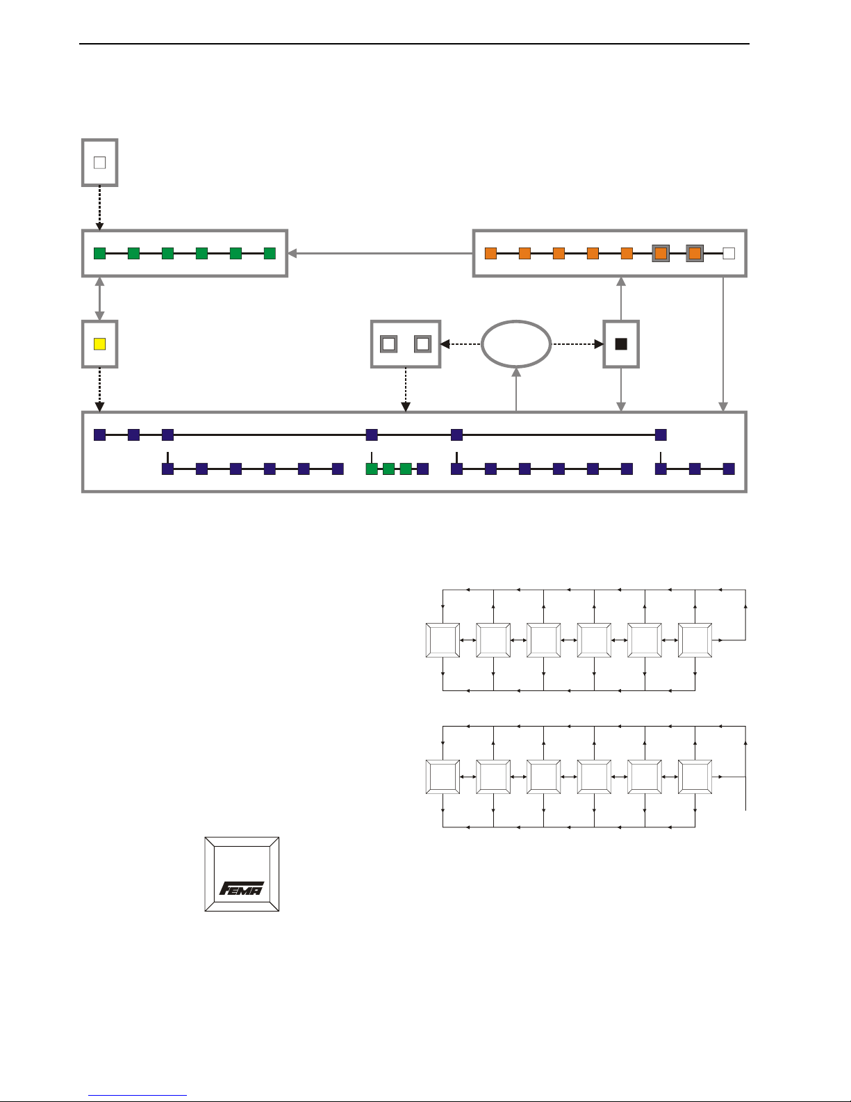
Fig. 1. Sequence of screens - Overview (DCM)
Devices equipped with an HMI (Human-Machine-Interface)
feature pushbuttons and a display, allowing easy
configuration by means of a menu structure. The menu
structure is divided into the following segments:
• The START SCREEN;
• The DISPLAY LEVEL (where information including the
current pressure and parameterized values are shown but
cannot be edited);
• The CODE area (where you will have to enter the correct
four-digit CODE in order to proceed any further);
• The PARAMETRIZATION LEVEL (where you can edit
various different parameters);
• A ERROR-CHECKING area (where the device will check
the plausibility of your values and, if necessary, redirect
you back to the PARAMETRIZATION LEVEL); and
• The CONFIRMATION LEVEL (where you can review your
edited values before permanently storing them).
START SCREEN
Within 10 seconds of powering-up the device, an initial screen
– the START SCREEN - will appear briefly (see Fig. 2).
Startup
Fig. 2. Start screen
You will then be automatically directed to the DISPLAY
LEVEL.
DISPLAY LEVEL
In the DISPLAY LEVEL, you can view the current pressure as
well as the various different user-settings currently in force.
Reset-pt.
Monitor Function
Drop in
delay
0s
Drop
out delay
0s
4.00bar Window N.C.
MENU MENU MENU MENU MENU
-0.90
bar
Closed
MENU
NEXT
PREVIOUS
NEXT
NEXT
NEXT
NEXT
NEXT
PREVIOUS
PREVIOUS
PREVIOUS
PREVIOUS
PREVIOUS
Set-pt.
5.00bar
MENU
NEXT
PREVIOUS
ESCAPE ESCAPE ESCAPE ESCAPE ESCAPE ESCAPE
Fig. 3. DISPLAY LEVEL
ENTERING THE ENTRY CODE
In order to gain access to the PARAMETRIZATION LEVEL
(where you can edit values), it is first necessary to show that
you have the requisite authorization by entering the correct
four-digit ENTRY CODE (default: 0000).
CODE
NOT
V
ALID
Put code
0000
OK
-
+
0
Put code
0000
-
+
8
Put code
0000
-
+
9
Put code
0009
-
+
0
Put code
0009
-
+
1
Put code
0009
-
+
4
Put code
0009
-
+
5
ESCAPE
OK OK
LEFT LEFT LEFT
OK OK OK OK
Put code
0000
-
+
1
OK
LEFT
LEFT LEFT LEFT LEFT
Fig. 4. Entering the ENTRY CODE
SMART DCM SWITCH – OPERATING INSTRUCTIONS
MU2B-0328GE51 R0207A
3
PARAMETRIZATION LEVEL
Once you have successfully entered the ENTRY CODE and
thus gained access to the PARAMETRIZATION LEVEL, you
can edit values and reconfigure the device.
NOTE: The currently set option (e.g. "yes," "no," "window
monitor", etc.) is always marked in the display
screen with a small dot to the left (see Fig. 5).
Monitor
Max.
OK
Window
ESCAPE
Monitor
Max.
Window
ESCAPE
OK
DOT
Fig. 5. Dot indicating present setting
SET-PT.
In this screen, you can select the set-point. This is defined as
the pressure at which you want the device to switch.
The default setting is 60% of full-scale.
ERROR MESSAGE: "VALUE OUT OF RANGE"
If you have entered a set-point outside of the device's
specified pressure measurement range or which is for any
other reason not rational, this error message will appear,
whereupon you should then enter a correct value.
RESET-PT.
In this screen, you can select the reset-point. This is defined
as the pressure at which you want the device to switch back.
The default setting is 40% of full-scale.
ERROR MESSAGE: "VALUE OUT OF RANGE"
If you have entered a reset-point outside of the device's
specified pressure measurement range or which is for any
other reason not rational, this error message will appear,
whereupon you should then enter a correct value.
OUTPUT
MONITOR
Here, you can choose between three types of monitors: min.,
max., and window.
• Min.;
• Max.;
• Window;
See Fig. 7 on page 5 for an explanation of the meanings of
these different settings.
The default setting is "Max."
FUNCTION
Here, you can choose the type of action you want the DCM
Switch to have:
• N.O.: Normally-open switch (meaning: when the switch is
activated, it will CLOSE); or
• N.C.: Normally-closed switch (meaning: when the switch
is activated, it will OPEN).
See Table 2 and Fig. 7 on page 5 for more information.
The default setting is "N.O."
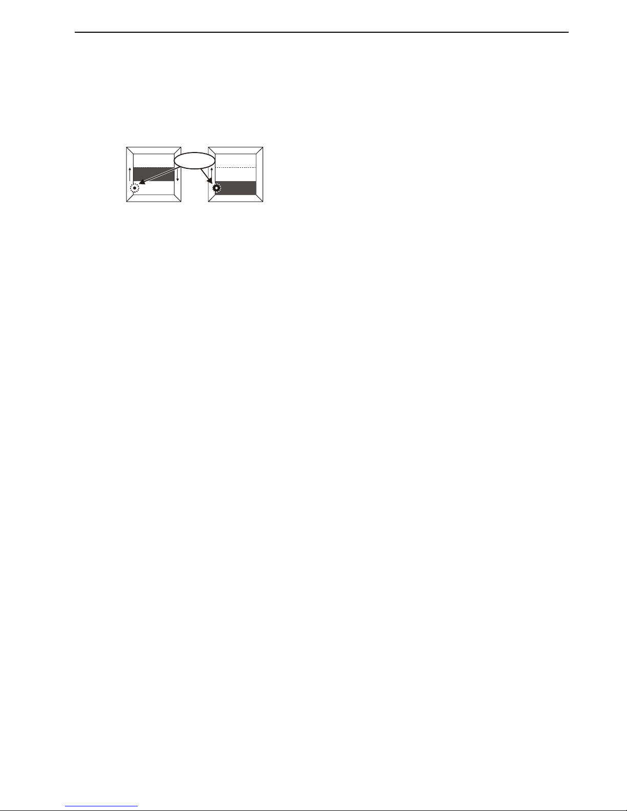
AUTO ZERO
The purpose of the auto zero function is to allow the user to
adjust the device to local ambient atmospheric pressure and
to compensate for drift. To use this function properly, the
device must be mounted in the application and the pressure
sensor exposed to local ambient atmospheric pressure (i.e.
0 bar relative pressure).
• Yes: The device takes the current local ambient
atmospheric pressure as its zero.
• No: The device setting remains unchanged.
The default setting is "No".
SET ZERO
The difference between the pressure value you enter in this
screen and the pressure which the device is currently
measuring will be taken as the offset. This offset can be reset
to zero using the reset zero option (see section "Reset Zero"
below).
The default setting is the pressure which the device is
currently measuring (meaning that the offset is then zero).
ERROR MESSAGE: "VALUE OUT OF RANGE"
If you have set a zero outside the permissible range (±25%
full-scale), this error message will appear, whereupon you
should then enter a correct value.
RESET ZERO
Here, you can reset the zero:
• Yes: The pressure offset will be set to zero.
• No: The device setting remains unchanged.
The default setting is "No".
DROP-IN
Here, you can select the drop-in value. See also Fig. 8.
Possible values range from 0 to 99 seconds.
The default setting is "0" seconds.
DROP-OUT
Here, you can select the drop-out value. See also Fig. 8.
Possible values range from 0 to 99 seconds.
The default setting is "0" seconds.
PEAKS
Here, you can view the historical max. and min. measured
pressures as well as the max. measured temperature
(historical = measured since the device has been put into
operation / since the last time the peaks were cleared).
If desired, by proceeding to "Clear" and choosing "yes," you
can also permanently erase all such values. All such peaks
will then be erased and the recording of peaks will be reinitiated.
DISPLAY
Here, you can select/alter various modes of displaying screen
information.
UNIT
Here, you can choose the units in which the device displays
pressures:
• bar: All pressures will be displayed in bars.
• Pa: All pressures will be displayed in Pascals.
• Psi: All pressures will be displayed in pounds / in2.
The default setting is "bar".
LANGUAGE
English is the only supported language.

SMART DCM SWITCH – OPERATING INSTRUCTIONS
MU2B-0328GE51 R0207A
4
BACKLIGHT
Here, you can select how the device's screen backlight
should operate:
• Always: The backlight will remain ON at all times.
• Demand: The backlight will come ON whenever the
device's keys are operated, and remain ON for 25 s.
• Never: The backlight is shut OFF permanently.
The default setting is "Never".
REFRESH
Here, you can set how often (in seconds) the screen contents
should be refreshed (i.e. refilled with freshly-measured data).
Possible values range from 1 to 9 seconds.
The default setting is "1" sec.
ROTATE
Here, you can permanently rotate (by 0°, 90°, 180°, or 270°)
the orientation in which the screen's contents are displayed.
This is for easier viewing / enhanced legibility.
The default setting is "0" degrees (i.e. screen contents vertical
when device mounted in upright position).
CONTRAST
Here, you can choose the degree of contrast with which the
screen's contents are displayed:
• Min.: The contrast is decreased to its minimum value;
• Mean: The contrast is set to its mean value;
• Max.: The contrast is increased to its maximum value.
The default setting is "Mean".
EXTRAS
SIMUL. (= SIMULATION MODE)
The simulation mode allows the user to test the device within
the application without actually applying pressure.
When the simulation mode is initiated, the device's diagnostic
features are not active, and use of the device in an active
safety application is impossible.
After leaving the simulation mode and returning to the normal
operating mode, the device is again ready for use in safety
applications.
• Yes: The simulation mode is started.
• No: The device remains in its normal operating mode.
The default setting is "No".
WARNING
After you have completed testing in the simulation mode, do
not forget to return to this screen and re-instate the active
operating mode.
SET CODE
Here, you can change the ENTRY CODE. After leaving the
PARAMETRIZATION LEVEL and proceeding through the
CONFIRMATION LEVEL, the new ENTRY CODE will then be
in effect.
RESET
Here, you can re-instate all factory (i.e. default) settings:
• Yes: All factory settings are re-instated.
• No: currently-set values are retained.
PLAUSIBILITY CHECK
Upon attempting to leave the PARAMETRIZATION LEVEL,
the device will determine two checks to determine the
plausibility of your values.
ERROR MESSAGE: "MIN. DISTANCE BETW. SET-PT. AND
RESET-PT. IS 0.5% FS. PLEASE CORRECT PARAMS"
The difference between the set-point and the reset-point will
be checked. If the distance is too small (i.e. less than 0.5% of
the full-scale), this error message will appear.
ERROR MESSAGE: "OFFSET MUST BE BETWEEN -25%FS &
+25%FS. PLEASE CORRECT"
The offset will also be checked. If the offset is not within 25%
of the full-scale, this error message will appear.
CONFIRMATION LEVEL
Here, you have the opportunity of once again viewing all of
the device's settings (including any changes you may have
made) in a quick overview. If you reject any settings, you will
be automatically redirected to the PARAMETRIZATION
LEVEL. If you accept all settings, these values will be
permanently stored, and you will be automatically redirected
to the DISPLAY LEVEL.
IMPORTANT
You should be completely satisfied with the correctness of the
settings displayed in the CONFIRMATION LEVEL. As soon
as you complete the CONFIRMATION LEVEL, all of these
settings will become effective.
SMART DCM SWITCH – OPERATING INSTRUCTIONS
MU2B-0328GE51 R0207A
5
OUTPUT DESCRIPTION
1
2
4
3
L+
L-
OC PNP
1
2
3
4
P
L+
L-
OC PNP
WARN
WARN
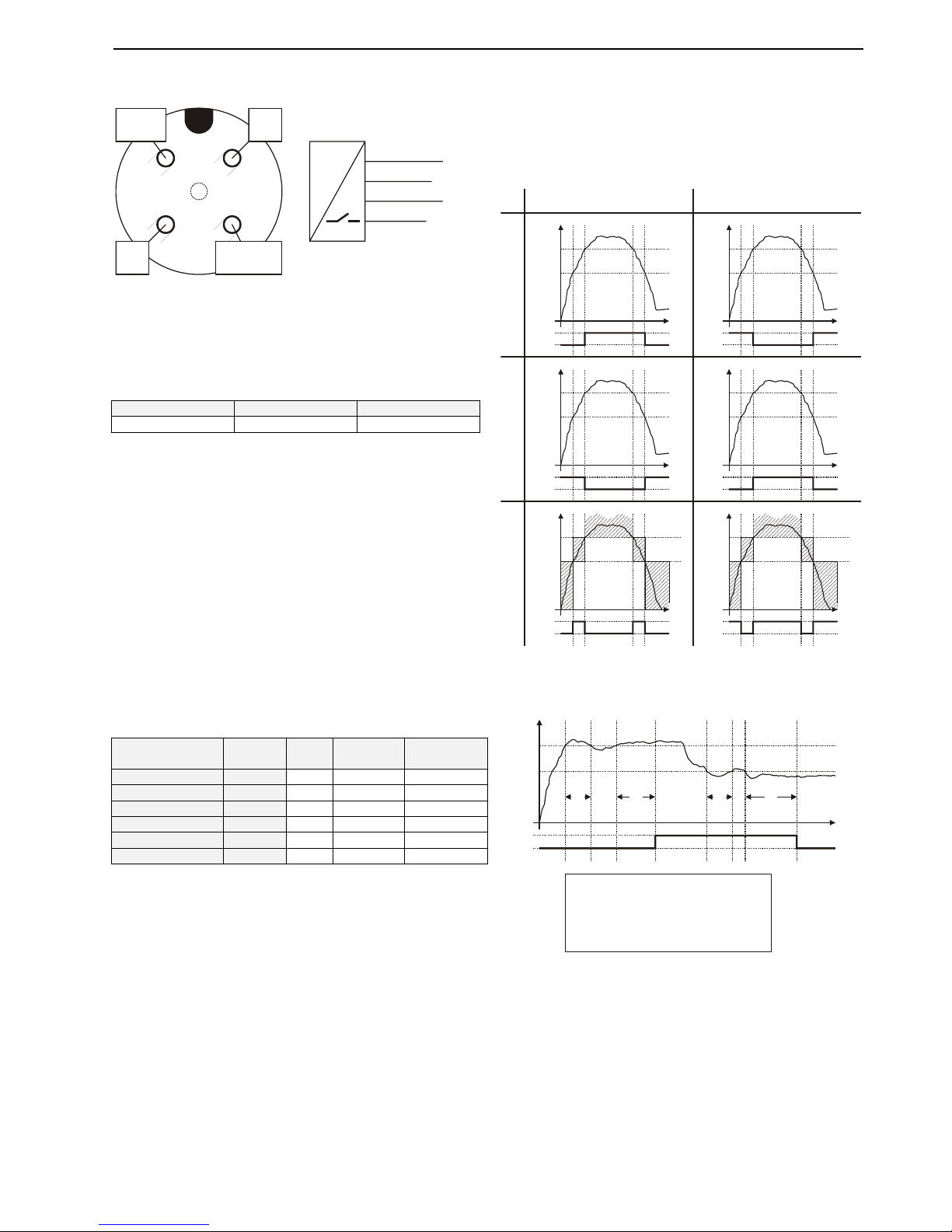
Fig. 6. Pin assignment of A-coded M12 plug
NOTE: The unit and any field devices (actuators, sensors,
etc.) to which it is electrically connected must be
provided with a common ground via pin 3.
The initial conditions of the device's signal outputs are as
follows:
Table 1. DCM Switch signal outputs after power-up
WARN (pin 2) POWER OUTPUT (pin 4)
passive -- open
NOTE: The WARN output (pin 2) is an auxiliary output
used for signaling errors. It cannot be used to drive
high loads.
DCM SWITCH BEHAVIOR IN OVERCURRENT
CONDITIONS
In order to prevent damage of the device electronics, the
device measures the current flowing into the load.
If the current flowing from the switch output to the load
exceeds 250 mA, the load is automatically disconnected and
the WARN output is set to < 0.5 V for 5 sec. The load is then
reconnected, the current is measured again, and the WARN
output is set to the power supply voltage. If the current is still
greater than 250 mA, the load is disconnected and the WARN
output is set to < 0.5 V… in a loop.
Table 2. DCM Switch functions and definitions
definition function
equa-
tion
"active" = "inactive" =
max. monitor N.O.
1 closed open
max. monitor N.C.
1 open closed
min. monitor N.O.
1 open closed
min. monitor N.C.
1 closed open
window monitor N.O.
2 closed open
window monitor N.C.
2 open closed
Equation 1 (min./max. monitor):
active x ≥ USP
y
n+1
= inactive x ≤ LSP
y
n
otherwise
Equation 2 (window monitor):
active LSP ≤ x ≤ USP
inactive x ≤ LSP minus (0.5%
±
range)
Inactive x ≥ LSP plus (0.5%
±
range)
y
n+1
=
yn otherwise
Where
y
n
is the analog output value as determined in the
previous cycle,
y
n+1
is the analog output value as determined in the current
cycle, and
x is the current measured pressure.
USP
USP
USP
LSP
LSP
LSP
NORMALLY-OPEN NORMALLY-CLOSED
time
time
time
p
p
p
closed
closed
closed
open
open
open
time
time
time
p
p
p
closed
closed
closed
open
open
open
USP
USP
USP
LSP
LSP
LSP
MAX. MONITORMIN. MONITORWINDOW MONITOR
Fig. 7. DCM Switch output (max./min./window monitor)
USP
LSP
time
p
closed
open
N.O. MAX. MONITOR (OR N.C. MIN. MONITOR)
T
1
T
3
T
2
T
4
LEGEND:
T less than drop-in time
T greater than or equal to drop-in time
T less than drop-out time
T greater than or equal to drop-out time
1
2
3
4
Fig. 8. Drop-in / drop-out time
SMART SN TRANSMITTER – OPERATING INSTRUCTIONS
MU2B-0328GE51 R0207A
6
SN TRANSMITTER
SEQUENCE OF SCREENS
MODE FUNCTION
OUTPUTSTART-PT END-PT
AUTO-0 SET ZERO RESET 0
PRESSURE,
STATE
START-PT.
WELCOME
END-PT. MODE FUNCTION ATTENUATION
MESSAGE MESSAGE
ATTENUATION
PEAKS
UNIT LANGU AGE BACKLIGHT REFRESH ROTATE CONTRAST
DISPLAY
CLEARMIN. MAX. TEMP. SIMUL. SET CODE RESET
EXTRAS
ENTER
CODE
GO TO
CONFIRM
A
LL
SETTINGS
PLAUSIBLE
?
NO YES
START-PT. END-PT. MODE FUNCTION ATTENUATION CODE SIMUL. STORING...
DISPLAY LEVEL
PARAMETRIZATION LEVEL
CODE
ERROR
START
CONFIRMATION LEVEL
Fig. 9. Sequence of screens – Overview (SN)
Devices equipped with an HMI (Human-Machine-Interface)
feature pushbuttons and a display, allowing easy
configuration by means of a menu structure. The menu
structure is divided into the following segments:
• The START SCREEN;
• The DISPLAY LEVEL (where information including the
current pressure and parameterized values are shown but
cannot be edited);
• The CODE area (where you will have to enter the correct
four-digit CODE in order to proceed any further);
• The PARAMETRIZATION LEVEL (where you can edit
various different parameters);
• A ERROR-CHECKING area (where the device will check
the plausibility of your values and, if necessary, redirect
you back to the PARAMETRIZATION LEVEL); and
• The CONFIRMATION LEVEL (where you can review your
edited values before permanently storing them).
START SCREEN
Within 10 seconds of powering-up the device, an initial screen
– the START SCREEN - will appear briefly (see Fig. 10).
Startup
Fig. 10. Start screen
You will then be automatically directed to the DISPLAY
LEVEL.
DISPLAY LEVEL
In the DISPLAY LEVEL, you can view the current pressure as
well as the various different user-settings currently in force.
Function
A
tt. filter
Non-inv. 10%
MENU
NEXT
PREVIOUS
End
pressure
10.00bar
Mode
2-wire
4..20mA
Start
pressure
0.00bar
MENU
NEXT
PREVIOUS
ESCAPE ESCAPE
MENU
NEXT
PREVIOUS
ESCAPE
NEXT
PREVIOUS
ESCAPE
MENU
NEXT
PREVIOUS
ESCAPE
MENU
0.22
bar
4.35mA
MENU
NEXT
PREVIOUS
Fig. 11. DISPLAY LEVEL (example: SN 2-Wire)
Function
Att. filter
Non-inv. 10%
MENU
NEXT
PREVIOUS
End
pressure
10.00bar
Mode
3-wire
0..10V
Start
pressure
0.00bar
MENU
NEXT
PREVIOUS
ESCAPE ESCAPE
0.22
bar
0.21V
MENU
NEXT
PREVIOUS
MENU
NEXT
PREVIOUS
ESCAPE
NEXT
PREVIOUS
ESCAPE
MENU
NEXT
PREVIOUS
ESCAPE
MENU
Fig. 12. DISPLAY LEVEL (example: SN 3-Wire)
ENTERING THE ENTRY CODE
In order to gain access to the PARAMETRIZATION LEVEL
(where you can edit values), it is first necessary to show that
you have the requisite authorization by entering the correct
four-digit ENTRY CODE (default: 0000).
SMART SN TRANSMITTER – OPERATING INSTRUCTIONS
MU2B-0328GE51 R0207A
7
CODE
NOT
V
ALID
Put code
0000
OK
-
+
0
Put code
0000
-
+
8
Put code
0000
-
+
9
Put code
0009
-
+
0
Put code
0009
-
+
1
Put code
0009
-
+
4
Put code
0009
-
+
5
ESCAPE
OK OK
LEFT LEFT LEFT
OK OK OK OK
Put code
0000
-
+
1
OK
LEFT
LEFT LEFT LEFT LEFT
Fig. 13. Entering the ENTRY CODE
PARAMETRIZATION LEVEL
Once you have successfully entered the ENTRY CODE and
thus gained access to the PARAMETRIZATION LEVEL, you
can edit values and reconfigure the device.
NOTE: The currently set option (e.g. "yes," "no,"
"4…20 mA", etc.) is always marked in the display
screen with a small dot to the left (see Fig. 5).
Function
N.O.
OK
N.C.
ESCAPE
Function
N.O.
N.C.
ESCAPE
OK
DOT
Fig. 14. Dot indicating present setting
START-PT.
In this screen, you can select the start-point. This is defined
as the pressure at which you want the device to begin
providing an analog output signal.
The default setting is "0".
ERROR MESSAGE: "VALUE OUT OF RANGE"
If you have entered a start-point outside of the device's
specified pressure measurement range or which is for any
other reason not rational, this error message will appear,
whereupon you should then enter a correct value.
END-PT.
In this screen, you can select the end point. This is defined as
the pressure at which you want the device to stop providing
an analog output signal.
The default setting is 100% of full-scale.
ERROR MESSAGE: "VALUE OUT OF RANGE"
If you have entered an end-point outside of the device's
specified pressure measurement range or which is for any
other reason not rational, this error message will appear,
whereupon you should then enter a correct value.
OUTPUT
MODE
Here, you can set the device's mode. Four different modes
are possible:
• 0…10V: the voltage range is set to 0…10 V;
• 0…20mA: the current range is set to 0…20 mA;
• 2…10V: the voltage range is set to 2…10 V;
• 4…20mA: the current range is set to 4…20 mA (default).
NOTE: The only mode supported by the SN 2-Wire Trans-
mitter is "4…20 mA". However, it can be inverted
to "20…4 mA" (see section "Function" below).
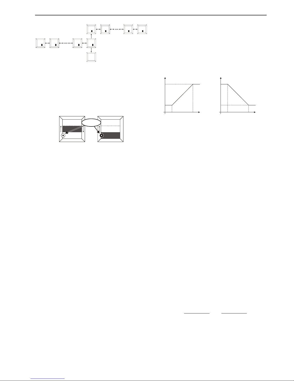
FUNCTION
Here, you can invert the device's function (see also Fig. 15):
• Non-invert.: the mode (current range or voltage range, as
the case may be) is set to 0/4…20 mA or 0/2…10 V (as
the case may be) (default);
• Inverted: the mode (current range or voltage range, as the
case may be) is set to 20…0/4 mA or 10…0/2 V (as the
case may be).
The default setting is "non-invert."
U/I
MAX MAX
U/I
MAX MAX
U/I
MIN MIN
U/I
MIN MIN
output U/I output U/I
NORMAL OPERATION INVERTED OPERATION
pressure pressure
pressure
start
pressure
start
pressure
end
pressure
end
Fig. 15. SN Transmitter output (normal/inverted)
AUTO ZERO
The purpose of the auto zero function is to allow the user to
adjust the device to local ambient atmospheric pressure and
to compensate for drift. To use this function properly, the
device must be mounted in the application and the pressure
sensor exposed to local ambient atmospheric pressure (i.e.
0 bar relative pressure).
• Yes: The device takes the current local ambient
atmospheric pressure as its zero.
• No: The device setting remains unchanged.
The default setting is "No".
SET ZERO
The difference between the pressure value you enter in this
screen and the pressure which the device is currently
measuring will be taken as the offset. This offset can be reset
to zero using the reset zero option (see section "Reset Zero"
below).
The default setting is the pressure which the device is
currently measuring (meaning that the offset is then zero).
ERROR MESSAGE: "VALUE OUT OF RANGE"
If you have set a zero outside the permissible range (±25%
full-scale), this error message will appear, whereupon you
should then enter a correct value.
RESET ZERO
Here, you can reset the zero:
• Yes: The pressure offset will be set to zero.
• No: The device setting remains unchanged.
The default setting is "No".
ATT. FILTER
Here, you can attenuate (dampen) the outputted portion of
the peak. Possible values range from 0 to 99%. The default
setting is "10" percent.
The formula for calculating the attenuation is as follows:
1
100
)
100
1(
−
+−=
nnn
y
nattenuatio
x
nattenuatio
y

SMART SN TRANSMITTER – OPERATING INSTRUCTIONS
MU2B-0328GE51 R0207A
8
Where
y
n
is the analog output value
x
n
is the measured offset-compensated pressure in this
cycle
y
n-1
is the analog output value generated in the previous
cycle
PEAKS
Here, you can view the historical max. and min. measured
pressures as well as the max. measured temperature
(historical = measured since the device has been put into
operation / since the last time the peaks were cleared).
If desired, by proceeding to "Clear" and choosing "yes," you
can also permanently erase all such values. All such peaks
will then be erased and the recording of peaks will be reinitiated.
DISPLAY
Here, you can select/alter various modes of displaying screen
information.
UNIT
Here, you can choose the units in which the device displays
pressures:
• bar: All pressures will be displayed in bars.
• Pa: All pressures will be displayed in Pascals.
• Psi: All pressures will be displayed in pounds / in2.
The default setting is "bar".
LANGUAGE
English is the only supported language.
BACKLIGHT
Here, you can select how the device's screen backlight
should operate:
• Always: The backlight will remain ON at all times.
• Demand: The backlight will come ON whenever the
device's keys are operated, and remain ON for 25 sec.
• Never: The backlight is shut OFF permanently.
The default setting is "Never"
NOTE: The only backlight option supported by the SN 2-
Wire Transmitter is "Never."
REFRESH
Here, you can set how often (in seconds) the screen contents
should be refreshed (i.e. refilled with freshly-measured data).
Possible values range from 1 to 9 seconds.
The default setting is "1" sec.
ROTATE
Here, you can permanently rotate (by 0°, 90°, 180°, or 270°)
the orientation in which the screen's contents are displayed.
This is for easier viewing / enhanced legibility.
The default setting is "0" degrees (i.e. screen contents vertical
when device mounted in upright position).
CONTRAST
Here, you can choose the degree of contrast with which the
screen's contents are displayed:
• Min.: The contrast is decreased to its minimum value;
• Mean: The contrast is set to its mean value;
• Max.: The contrast is increased to its maximum value.
The default setting is "Mean".
EXTRAS
SIMUL. (= SIMULATION MODE)
The simulation mode allows the user to test the device within
the application without actually applying pressure.
When the simulation mode is initiated, the device's diagnostic
features are not active, and use of the device in an active
safety application is impossible.
After leaving the simulation mode and returning to the normal
operating mode, the device is again ready for use in safety
applications.
• Yes: The simulation mode is started.
• No: The device remains in its normal operating mode.
The default setting is "No".
WARNING
After you have completed testing in the simulation mode, do
not forget to return to this screen and re-instate the active
operating mode.
SET CODE
Here, you can change the ENTRY CODE. After leaving the
PARAMETRIZATION LEVEL and proceeding through the
CONFIRMATION LEVEL, the new ENTRY CODE will then be
in effect.
RESET
Here, you can re-instate all factory (i.e. default) settings:
• Yes: All factory settings are re-instated.
• No: currently-set values are retained.
PLAUSIBILITY CHECK
Upon attempting to leave the PARAMETRIZATION LEVEL,
the device will perform two checks to determine the
plausibility of your values.
ERROR MESSAGE: "MIN. DISTANCE BETW. START-PT. AND
END-PT. IS 50% FS. PLEASE CORRECT PARAMS"
The difference between the set-point and the reset-point will
be checked. If the distance is too small (i.e. less than 50% of
the full-scale), this error message will appear.
ERROR MESSAGE: "OFFSET MUST BE BETWEEN -25%FS &
+25%FS. PLEASE CORRECT"
The offset will also be checked. If the offset is not within 25%
of the full-scale, this error message will appear.
CONFIRMATION LEVEL
Here, you have the opportunity of once again viewing all of
the device's settings (including any changes you may have
made) in a quick overview. If you reject any settings, you will
be automatically redirected to the PARAMETRIZATION
LEVEL. If you accept all settings, these values will be
permanently stored, and you will be automatically redirected
to the DISPLAY LEVEL.
IMPORTANT
You should be completely satisfied with the correctness of the
settings displayed in the CONFIRMATION LEVEL. As soon
as you complete the CONFIRMATION LEVEL, all of these
settings will become effective.

SMART SN TRANSMITTER – OPERATING INSTRUCTIONS
MU2B-0328GE51 R0207A
9
OUTPUT DESCRIPTION
PTS...V3PTH... PTS...A3 PTS...A2
1
2
4
3
1
2
3
4
P
U/I
L+/
~
L-/
~
WARN
WARN
U/I
OUT
L+/
~
L-/
~
1
2
4
3
1
2
3
4
P
U
WARN
WARN
U
OUT
L+/
~
L-/
~
L+/
~
L-/
~
1
2
4
3
1
2
3
4
P
I
WARN
WARN
I
OUT
L+/
~
L+/
~
L-/
~
L-/
~
1
2
4
3
L+
L-
n.c.
n.c.
1
2
3
4
P
I
L+
n.c.
n.c.
L-
Fig. 16. Pin assignment of A-coded M12 plug
NOTE: The unit and any field devices (actuators, sensors,
etc.) to which it is electrically connected must be
provided with a common ground via pin 3.
The initial conditions of the device's signal outputs are as
follows:
Table 3. SN Transmitter signal outputs after power-up
device
output
signal range
WARN power
output
(pin 4)
2-Wire 4…20 mA not used < 3.6 mA not used
4…20 mA passive -- 0 mA
2…10 V passive -- 2 V
0…20 mA passive -- 0 mA
3-Wire
0…10 V passive -- 0 V
The output limits of the device's outputs at overpressure and
underpressure are as follows:
Table 4. SN Transmitter output limits at over- /
underpressure
device
output signal
range
min. output
limit
max. output
limit
2-Wire 4…20 mA 3.8 mA 20.5 mA
4…20 mA 3.8 mA 20.5 mA
2…10 V 1.8 V 10.5 V
0…20 mA 0 mA 20.5 mA
3-Wire
0…10 V 0 V 10.5 V
Table 5. SN Transmitter parameters
parameter description range
analog
start-pt.
pressure mapped to
upper limit of output
range
min. pressure (analog
end minus 50%FS)
analog endpt.
pressure mapped to
lower limit of output
range
max. pressure (analog
start plus 50%FS)
offset
user-adjustable offset to
compensate for local
atmospheric pressure
and drift
±25%FS
definition selection of output signal
0…20 mA, 4…20 mA
0…10 V, 2…10 V
function
selecting normal /
inverted output
characteristics
non-inverted; inverted
attenuation
weight (in %) of previous
value in attenuation filter
0.95

SMART DCM SWITCH / SN TRANSMITTER – OPERATING INSTRUCTIONS
MU2B-0328GE51 R0207A
10
REMARKS AS PER EN 61010-1
PREREQUISITES FOR MOUNTING
The unit is not suitable for mounting in explosive environments.
The unit may be operated only within the specified technical
limits.
CONNECTION
In the case of units with stationary mounting, the following
requirements must be observed:
Minimum cross-sectional diameter of wiring: 0.75 mm2
POWER FAILURE
In the event of a power failure, the device will cease
operation. After power is returned, the device will, after a brief
(2-3 sec) initialization period, resume normal functioning.
Because its memory is stored on EPROM, no reparametrization is necessary.
CLEANING AGENTS
All commercial cleaning agents approved for use in the food
industry and for stainless steel 1.4571 are permitted.
MISUSE OF UNIT
Installing/operating this device contrary to these Operating
Instructions can impair its proper functioning / result in
malfunctioning and device damage - result in danger of injury.
RECALIBRATION
It is not possible to recalibrate the device in the field, nor does
it contain any field-reparable parts. For recalibration or repair,
contact FEMA.
SAFETY FUNCTION (D.C. SUPPLY,
ONLY)
SN TRANSMITTER
Measuring pressures is the safety function of the directcurrent-driven devices. It is applicable for 2-wire (4…20 mA)
and 3-wire versions (0/4…20 mA and 0/2…10 V with auxiliary
WARN output) and ensures an accuracy of 5% of the
measured value within this range.
The safety function ensures that, in the worst-case scenario,
the diagnosis function responds within 45 seconds.
The transmitter's output is updated according to Fig. 15 on
page 7. The X-axis of the characteristic indicates the
measured pressure after application of the offset compensation and the attenuation filter. The Y-axis displays the
generated output in the range according to the output
definition (see Fig. 15 on page 7 and Table 5 on page 9).
DCM SWITCH
Measuring pressures is the safety function of the directcurrent-driven devices. The device will act within an accuracy
of 5% as a Max., Min., or Window monitor (switch output and
auxiliary WARN output), depending upon the device settings.
The switch output is in the "open" state (see Table 7)
whenever the prerequisites for the "open" state are fulfilled.
ERROR STATES
While the device is in operation, it provides continuous
supervision. The diagnostics detect errors in the application
(e.g. when the desired output signal is not reached), in the
electronics (e.g. in the event of miswiring or defective
circuitry), as well as sensor defects and runtime errors in the
software.
If an error occurs, it will be signalized on the signal output
and/or WARN output within a maximum of 45 seconds, and
the display illumination will turn RED and remain RED until
the error has been eliminated.
There are two classes of errors: recoverable errors and
unrecoverable errors.
RECOVERABLE ERRORS
Recoverable errors can be solved by a software reset:
After the error is recognized, it is reported at the signal output
and the WARN output for 5 seconds. After that, the device
performs an automatic software reset (i.e. the signal output
will go into the start-up condition and the device will be reinitialized). The device will then resume normal operation.
UNRECOVERABLE ERRORS
If (after an automatic software reset) the error is still detected
or it recurs during the next 10 minutes of operation, the error
is reclassified as unrecoverable. This means that it cannot be
resolved without interaction of the user. If, however, the error
does not recur within 10 minutes, the device will resume
normal operation.
Unrecoverable errors can be resolved only by means of a
hardware reset. A hardware reset is performed by
disconnecting the device from the power supply for at least 10
seconds.

SMART DCM SWITCH / SN TRANSMITTER – OPERATING INSTRUCTIONS
MU2B-0328GE51 R0207A
11
REMEDYING AN UNRECOVERABLE ERROR SETTING
If an unrecoverable error is indicated, you can try to solve the
issue by powering down the device and eliminating the error
conditions (e.g. miswiring, overtemperature, overpressure).
A hardware reset is performed by disconnecting the device
from the power supply for at least 10 seconds.
NOTE: If the error persists, contact FEMA.
OUTPUT LEVELS AND OUTPUT BEHAVIOR
SN TRANSMITTER
2-WIRE VERSION
The 2-wire version signalizes an error via the current loop
signal.
3-WIRE VERSION
NOTE: If either analog range 0…10 V or analog range
0…20 mA is used, then the WARN output must
also be used.
The 3-wire version signalizes an error via the signal output
(pin 4) and the WARN output (pin 2).
If (due to miswiring or electronic failure) the signal output
cannot reach the desired "high" failure state, it will automatically go to the "low" failure state.
Table 6. SN Transmitter error reporting
error reporting
device
output
signal
range
primary,
"high" failure
state
secondary,
"low" failure
state
WARN
output
(pin 2)
2-wire 4…20 mA
loop current >
21 mA
loop current <
3.6 mA
NOTE 1
0…20 mA
output >
21 mA
output = 0 mA
NOTE 2
< 0.5 V
4…20 mA
output >
21 mA
output <
3.6 mA
< 0.5 V
0…10 V output > 11 V
output = 0 V
NOTE 2
< 0.5 V
3-wire
2…10 V output > 11 V output < 1.5 V < 0.5 V
NOTE 1: The 2-Wire Transmitter has no WARN output.
NOTE 2: This a valid signal; it is therefore necessary to use
the WARN output.
DCM SWITCH
Table 7. DCM Switch error reporting
error reporting
device
output
signal
range
primary,
"high" failure
state
secondary,
"low" failure
state
WARN
output
(pin 2)
switch
open /
closed
open open* < 0.5 V
*It is still necessary to use the WARN output to cover blocked
closed output transistor error.

SMART DCM SWITCH / SN TRANSMITTER – OPERATING INSTRUCTIONS
Manufactured for and on behalf of the Environmental and Combustion Controls Division of Honeywell Technologies Sàrl, Ecublens, Route du Bois 37, Switzerland by its Authorized Representative:
Fema Controls
Honeywell GmbH
P.O. Box 1254
D-71099 Schönaich
phone: (49) 7031-637-02
fax: (49) 7031-637-850
http:/honeywell.de/fema
Subject to change without notice. Printed in Germany
MU0B-0560GE51 R0207A
ERROR MESSAGES
Table 8 lists all error messages which can appear in the display screen during operation.
Table 8. SN Transmitter / DCM Switch error messages
screen
contents
description / cause
recoverable /
unrecoverable
remedy
0 No error. -- No action necessary.
1 Electronics failure. R/U If unrecoverable: Contact FEMA.
4 Electronics failure or sensor failure. R/U If unrecoverable: Contact FEMA.
5 Electronics failure or miswiring. R/U
Check wiring (current meter used for current
output? Voltmeter used for voltage output?).
Correct detected errors and perform a hardware reset as described above. If
unrecoverable: Contact FEMA.
6 Device memory check failure. R/U
Hardware reset as described above. Contact
FEMA.
7 Device program flow failure. R/U If unrecoverable: Contact FEMA.
8 Environment too hot or electronics failure. U
Eliminate overtemperature conditions. Perform
hardware reset as described above. Contact
FEMA.
10 Electronics failure. U Contact FEMA.
11 Electronics failure or data processing error. U Contact FEMA.
12 Data processing error. R/U If unrecoverable: Contact FEMA.
13
Pressure exceeds overpressure, resulting in
sensor failure.
U
Eliminate overpressure conditions. Perform
hardware reset as described above. If this
does not help: Contact FEMA.
15 Device memory check failure. R/U
Perform hardware reset as described above. If
this does not help: Contact FEMA.
16 Electronics (microcontroller) failure. R/U If unrecoverable: Contact FEMA.
17 Damage to application state data. R/U
Perform hardware reset as described above. If
this does not help: Contact FEMA.
18 Electronics error. R/U If unrecoverable: Contact FEMA.
19 Electronics or data processing error. R/U If unrecoverable: Contact FEMA.
20 Electronics or sensor error. R/U If unrecoverable: Contact FEMA.
21 Electronics error. R/U If unrecoverable: Contact FEMA.
22 Electronics or data processing error. U Contact FEMA.

® U.S Registered Trademark
Copyright © 2007 Honeywell Inc. • All Rights Reserved MU2B-0328GE51 R0207A
Smart SN, DCM
ELEKTRONISCHE DRUCKSCHALTER UND -TRANSMITTER
BEDIENUNGSANLEITUNG
ALLGEMEINES
Druckschalter der Baureihe Smart DCM sowie Drucktransmitter der Baureihe Smart SN von Honeywell FEMA sind
mikroprozessor-gesteuerte Druckmessgeräte zur Messung
von Relativdrücken von -1…+1 bar und 0…40 bar. Sie sind
bestens geeignet für vielfältige Einsatzbereiche, u.a. zur
genauen Erfassung, Überwachung und Regelung von
Systemdrücken. Der M12x1 Winkelstecker ist im Lieferumfang enthalten. Die Geräte werden direkt in die Druckleitung oder den Druckbehälter eingeschraubt (G1/2").
BITTE BEACHTEN!
GÜLTIGKEIT
Diese Bedienungsanleitung bezieht sich auf Meßsysteme, die
Smart DCM Druckschalter bzw. Smart SN Drucktransmitter
beinhalten. Geräte-Software Version 1.30 oder höher ist
Voraussetzung.
VERWENDUNG
Bei der Konfiguration und Inbetriebnahme des Geräts darf
nur diese Bedienungsanleitung (sowie die dazugehörigen
Montageanleitungen) verwendet werden. Nur qualifizierte
Fachkräfte dürfen das Gerät einbauen, einstellen, in Betrieb
nehmen und warten. Das Gerät ist ausschließlich unter den
vorliegenden Bedingungen und zu den vorgesehenen
Zwecken zu betreiben.
TECHNISCHE DATEN
Werkstoffe
Mediumberührte Teile Edelstahl (1.4571)
Chemische Beständigkeit 4C4 gemäß EN 60721-3-4
HMI PA66 GF25
Gesamtgewicht 300 g ohne, 350 g mit HMI
Umgebungstemperatur und -feuchtigkeit (bei Betrieb)
Versionen ohne HMI -20...+80 °C
Versionen mit HMI -20...+70 °C
Rel. Luftfeuchtigkeit 0...95%, nicht-kondensierend
Mediumtemperatur -30...+100 °C (≤ 16 bar-Modelle)
-40...+100 °C (> 16 bar-Modelle)
Lagertemperatur
Versionen ohne HMI -40...+80 °C (≤ 16 bar)
-40...+100 °C (> 16 bar)
Versionen mit HMI -30...+80 °C
Klimaklasse
Innenräume 4K4H gemäß EN 60721-3-4
Im Freien 3K8H gemäß EN 60721-3-3
Mechanische Festigkeit
Schwingungen 20 g gem. IEC 68-2-6 (bis
2000 Hz)
Mechan. Erschütterungen 100 g gemäß IEC 68-2-27
Druckbeständigkeit / Genauigkeit (kombinierte
Nichtlinearität, Hyst. und Reproduzierbarkeit bei 20 °C)
Druckbereich P ≤ 16 bar P > 16 bar
Überdruckbeständigkeit 2x P
nominal
2x P
nominal
Berstbeständigkeit 4x P
nominal
10x P
nominal
Fühlertyp Piezo Dünnfilm
Genauigkeit
max. ±0,8% FS
±0,5% FS (typ.)
max. ±1% FS
±0,6% FS (typ.)
Druckmessbereich 0…40 bar, -1…1 bar
Taktzeit 100 ms
EMV gemäß EN 61326
Schutzklasse 2 gemäß EN 61010
Schutzart (ohne HMI) IP67 gemäß EN 60529-2
Schutzart (mit HMI) IP65 gemäß EN 60529-2
Prozessanschluss G1/2" Außengewinde
Elektrischer Anschluß 4-poliger M12x1-Stecker, "A"
Schalter
Ausg., oberer Wert (min.) V
VERSORG
- 2 V
Ausg., unterer Wert (max.) GND plus 0,5 V
Antwortzeit max. 300 ms
WARN-Ausg.-Spannung passiv: V
VERSORG
- 2 V
aktiv: ≤ 0,5 V
Transmitter (analog) Ausgang
Strom (2-Leiter) 4…20 mA
Spannung/Strom (3-Leiter) 0/2...10 V, 0/4...20 mA
Spannungsvers. (2-Leiter) 18…35 Vdc
Spannungsvers. (3-Leiter) 18…35 Vdc, 24 Vac +10%/-20%,
max. 50 mA
Stromausg. (max. Bürde) (V
VERSORG
- 16 V) / 22 mA
(max. Fehler ±0,25% FS)
Spann.-Ausgang (min. Last) 15 kΩ (max. Fehler ±0,25% FS)
Sprungantwort ca. 200 ms
Messbereich, Kalibrierung und Langzeitdrift (innerhalb
Temperaturkompensationsbereich von 0…80 °C)
max. typisch
Temp.-Einfluss auf Messb. ±0,3% FS / 10 K ±0,2% FS / 10 K
Temp.-Einfluss auf Kalib. ±0,3% FS / 10 K ±0,2% FS / 10 K
Langzeitdrift ±0,3% FS p.a. ±0,2% FS p.a.

SMART DCM SCHALTER – BEDIENUNGSANLEITUNG
MU2B-0328GE51 R0207A
14
DCM SCHALTER
MENÜNAVIGATION
MONITOR FUNCTION
OUTPUTSET-PT RESET-PT
AUTO-0 SET ZERO RESET 0
PRESSURE,
STATE
SET-PT.
WELCOME
RESET-PT. MONITOR FUNCTION DROP-IN DROP-OUT
MESSAGE MESSAGE
DROP-IN DROP-OUT
PEAKS
UNIT LANGUAGE BACKLIGHT REFRESH ROTATE CONTRAST
DISPLAY
CLEARMIN. MAX. TEMP. SIMUL. SET CODE RESET
EXTRAS
ENTER
CODE
GO TO
CONFIRM
A
LL
SETTINGS
PLAUSIBLE
?
NO
Y
ES
SET-PT. RESET-PT. MONITOR F UNCTION DROP-IN DROP-OUT CODE SIMUL. STORING...
DISPLAY LEVEL
PARAMETRIZATION LEVEL
CODE
ERROR
START
CONFIRMATION LEVEL
Abb. 1. Menünavigation - Übersicht (DCM)
Geräte, die mit einem HMI-Kopf ausgestattet sind, vereinfachen die Konfiguration mit Hilfe der Drucktasten und einer
Anzeige. Die am Rande angezeigten Begriffe und Symbole
erleichtern die Navigation durchs Menü.
Das Menü läßt sich in folgende Bereiche aufteilen:
• STARTANZEIGE;
• DISPLAY-BEREICH (Informationsanzeige einschließlich
des aktuellen Drucks, sowie verschiedener Einstellwerte.
Editieren ist hier nicht möglich);
• CODE-BEREICH (Eingabe des vierstelligen CODEs, um
in die nächste Ebene zu gelangen);
• PARAMETRISIERUNGSBEREICH (Änderung
verschiedener Einstellwerte);
• PRÜFBEREICH (Überprüfung auf korrekte Eingabe und
ggfls. Zurückstufung in den PARAMETRISIERUNGSBEREICH); und
• BESTÄTIGUNGSBEREICH (Nochmalige Bestätigung der
Einstellwerte, bevor sie dauerhaft gespeichert werden).
STARTANZEIGE
Binnen 10 Sekunden nach Einschalten des Geräts erscheint
als erstes die STARTANZEIGE (siehe Abb. 2).
Startup
Abb. 2. Startanzeige
Danach gelangen Sie automatisch in den DISPLAYBEREICH.
DISPLAYBEREICH
Im DISPLAYBEREICH können Sie den aktuellen Druck sowie
diverse andere Einstellwerte sehen.
Reset-pt.
Monitor Function
Drop in
delay
0s
Drop
out delay
0s
4.00bar Window N.C.
MENU MENU MENU MENU MENU
-0.90
bar
Closed
MENU
NEXT
PREVIOUS
NEXT
NEXT
NEXT
NEXT
NEXT
PREVIOUS
PREVIOUS
PREVIOUS
PREVIOUS
PREVIOUS
Set-pt.
5.00bar
MENU
NEXT
PREVIOUS
ESCAPE ESCAPE ESCAPE ESCAPE ESCAPE ESCAPE
Abb. 3. DISPLAYBEREICH
EINGABE DES ZUGANGSCODES
Um in den PARAMETRISIERUNGSBEREICH zu gelangen
und dort Einstellwerte ändern zu können, müssen Sie sich
zuerst mit der erforderlichen Autorisierung ausweisen. Dies
geschieht durch Eingabe des vierstelligen ZUGANGSCODEs
(Standardwert: 0000).
CODE
NOT
V
ALID
Put code
0000
OK
-
+
0
Put code
0000
-
+
8
Put code
0000
-
+
9
Put code
0009
-
+
0
Put code
0009
-
+
1
Put code
0009
-
+
4
Put code
0009
-
+
5
ESCAPE
OK OK
LEFT LEFT LEFT
OK OK OK OK
Put code
0000
-
+
1
OK
LEFT
LEFT LEFT LEFT LEFT
Abb. 4. Eingabe des ZUGANGSCODEs

SMART DCM SCHALTER – BEDIENUNGSANLEITUNG
MU2B-0328GE51 R0207A
15
PARAMETRISIERUNGSBEREICH
Nach Eingabe des richtigen ZUGANGSCODE und Gelangen
in den PARAMETRISIERUNGSBEREICH können Sie
Einstellwerte ändern sowie das Gerät umkonfigurieren.
HINWEIS: Die aktuelle Einstellung (z.B. "Ja", "Nein",
"Window-Wächter" usw.) ist an einem kleinen
Punkt zu erkennen (siehe Abb. 5).
Monitor
Max.
OK
Window
ESCAPE
Monitor
Max.
Window
ESCAPE
OK
DOT
Abb. 5. Kennzeichnung der akt. Einstellung
SET-PT. (SCHALTPUNKT)
In diesem Menüfenster können Sie den Schaltpunkt
einstellen. Der Schaltwert ist der Druck, bei dem das Gerät
schalten soll.
Die Werkseinstellung beträgt 60% von FS.
FEHLERMELDUNG: "VALUE OUT OF RANGE"
Falls Sie einen Schaltwert gewählt haben, der außerhalb des
zulässigen Druckmessbereichs oder inkorrekt ist, erscheint
diese Fehlermeldung, worauf hin Sie einen richtigen Wert
eingeben sollen.
RESET-PT. (RÜCKSCHALTPUNKT)
In diesem Menüfenster können Sie den Rückschaltpunkt einstellen. Der Rückschaltpunkt ist der Druck, bei dem das Gerät
zurückschalten soll.
Die Werkseinstellung beträgt 40% von FS.
FEHLERMELDUNG: "VALUE OUT OF RANGE"
Falls Sie einen Rückschaltwert gewählt haben, der außerhalb
des zulässigen Druckmessbereichs oder inkorrekt ist,
erscheint diese Fehlermeldung, worauf hin Sie einen richtigen
Wert eingeben sollen.
OUTPUT (AUSGABE)
MONITOR (ÜBERWACHUNGSMÖGLICHKEITEN)
Hier können Sie zwischen drei Überwachungsmöglichkeiten
wählen: "min.", "max." und "window".
• Min.;
• Max.;
• Window;
Siehe Abb. 7 auf S. 17 für eine Erklärung der Bedeutungen
der verschiedenen Einstellungen.
Die Werkseinstellung ist "Max."
FUNCTION (FUNKTION)
Hier können Sie das gewünschte Verhalten des DCM
Schalters wählen:
• N.O.: Schließer (d.h. bei Betätigung des Schalters
schließt er); oder
• N.C.: Öffner (d.h. bei Betätigung des Schalters öffnet er).
Siehe Tabelle 2 sowie Abb. 7 auf S. 17 für mehr
Informationen.
Die Werkseinstellung ist "N.O."
AUTO ZERO
Die "auto zero"-Funktion ermöglicht es dem Anwender, das
Gerät entsprechend den lokalen atmosphärischen Druckverhältnissen einzustellen sowie die Drift auszugleichen. Um
diese Funktion richtig anzuwenden, sollte das Gerät am
Einsatzort eingebaut und der Druckfühler dem örtlichen
Umgebungsdruck ausgesetzt sein (d.h. 0 bar Relativdruck).
• "Yes": Das Gerät übernimmt den örtlichen Umgebungsdruck als seinen Nullwert.
• "No": Die Geräteeinstellung bleibt unverändert.
Die Werkseinstellung ist "No".
SET ZERO (NULLABGLEICH)
Der Unterschied zwischen dem Druckwert, den Sie in diesem
Menüfenster eingeben, und dem aktuell gemessenen Druck
stellt den Offset (Nullabgleich) dar. Dieser Nullabgleich kann
mit dem "reset zero"-Option (siehe unten) wieder auf Null
gestellt werden.
Die Standardeinstellung ist der aktuell gemessene Druck (d.h.
der Nullabgleich beträgt dann Null).
FEHLERMELDUNG: "VALUE OUT OF RANGE"
Falls Sie einen "Nullabgleich" gewählt haben, der außerhalb
des zulässigen Bereichs (±25% FS) liegt, erscheint diese
Fehlermeldung, worauf hin Sie einen richtigen Wert eingeben
sollen.
RESET ZERO
Hier können Sie den Nullwert wieder einstellen:
• "Yes": Der Nullabgleich wird auf "Null" gesetzt.
• "No": Die Geräteeinstellung bleibt unverändert.
Die Werkseinstellung ist "No".
DROP-IN (EINSCHALTVERZÖGERUNG)
Hier können Sie die Einschaltverzögerung einstellen. Siehe
Abb. 8.
Sie ist wählbar zwischen 0…99 Sekunden.
Die Werkseinstellung beträgt "0" Sekunden.
DROP-OUT (AUSSCHALTVERZÖGERUNG)
Hier können Sie die Ausschaltverzögerung einstellen. Siehe
Abb. 8.
Sie ist wählbar zwischen 0…99 Sekunden.
Die Werkseinstellung beträgt "0" Sekunden.
PEAKS (SPITZENWERTE)
Hier können Sie die historischen Maximal- und Minimaldrücke
sehen sowie die Maximaltemperatur (historisch = gemessen
seit Inbetriebnahme bzw. seit dem letzten Löschen der
Spitzenwerte).
Falls erwünscht, können Sie zu "Clear" ("Löschen") vorgehen
und "Yes" wählen; sämtliche gespeicherte Spitzenwerte
werden dadurch gelöscht und die Aufzeichnung von
Spitzenwerten wird wieder neu begonnen.
DISPLAY
Hier können Sie verschiedene Anzeigemodi auswählen.

SMART DCM SCHALTER – BEDIENUNGSANLEITUNG
MU2B-0328GE51 R0207A
16
UNIT (EINHEITEN)
Hier können Sie die Einheiten, in denen das Gerät den Druck
anzeigt, wählen:
• bar: Der Druck wird in bar angezeigt.
• Pa: Der Druck wird in Pascal angezeigt.
• Psi: Der Druck wird in pounds / in2 angezeigt.
Die Werkseinstellung ist "bar".
LANGUAGE (SPRACHE)
Die unterstützte Menüsprache ist ENGLISCH.
BACKLIGHT (HINTERGRUNDBELEUCHTUNG)
Hier können Sie die Hintergrundbeleuchtung einstellen:
• "Always": Die Hintergrundbeleuchtung bleibt immer EIN.
• "Demand": Die Hintergrundbeleuchtung geht an, sobald
eine Taste betätigt wird und erlischt nach 25 Sek.
• "Never": Die Hintergrundbeleuchtung ist dauerhaft AUS.
Die Werkseinstellung ist "Never".
REFRESH (AKTUALISIEREN)
Hier können Sie die Aktualisierungsrate (in Sekunden) des
Displayinhalts einstellen.
Mögliche Werte sind 1…9 Sekunden.
Die Werkseinstellung beträgt "1" Sek.
ROTATE (DREHEN)
Hier können Sie (zur besseren Lesbarkeit) die Ausrichtung
des Displays dauerhaft um 0°, 90°, 180° oder 270° drehen.
Die Werkseinstellung ist "0" Grad (d.h. senkrechte
Ausrichtung bei aufrechter Einbaulage).
CONTRAST (KONTRAST)
Hier können Sie den Kontrast des Displays einstellen:
• "Min.": Der Kontrast wird auf den Mindestwert eingestellt;
• "Mean": Der Kontrast wird auf den Mittelwert eingestellt;
• "Max.": Der Kontrast wird auf den Höchstwert eingestellt.
Die Werkseinstellung ist "Mean".
EXTRAS (ZUSATZFUNKTIONEN)
SIMUL. (SIMULATIONSMODUS)
Der Simulationsmodus ermöglicht es dem Anwender, die
reibungslose Funktion des Geräts zu prüfen, ohne das
System unter Druck zu setzen.
Nach Aufrufen des Simulationsmodus sind die Diagnostikfunktionen nicht wirksam, und das Gerät kann nicht in einer
echten Sicherheitsanwendung eingesetzt werden.
Nach Verlassen des Simulationsmodus und Rückkehr in die
normale Betriebsart kann das Gerät wieder in
Sicherheitsanwendungen eingesetzt werden.
• "Yes": Der Simulationsmodus wird aufgerufen.
• "No": Das Gerät bleibt in seiner normalen Betriebsart.
Die Werkseinstellung ist "No".
VORSICHT
Nach Abschluß Ihres Tests im Simulationsmodus müssen Sie
darauf achten, zu diesem Menüfenster zurückzukehren und
die normale Betriebsart wieder zu aktivieren.
SET CODE (CODE EINSTELLEN)
Hier können Sie den ZUGANGSCODE neu definieren. Nach
Verlassen des PARAMETRISIERUNGSBEREICHS und
Durchlauf durch den BESTÄTIGUNGSBEREICH wird der
neue ZUGANGSCODE dann wirksam.
RESET
Hier können Sie das Gerät wieder auf Werkseinstellung (d.h.
Standardwerte) zurücksetzen:
• "Yes": Alle Werkseinstellungen werden wieder wirksam.
• "No": Die aktuellen Einstellungen werden beibehalten.
PLAUSIBILITÄTSPRÜFUNG
Beim Versuch, den PARAMETRISIERUNGSBEREICH zu
verlassen, wird das Gerät eine automatische Prüfung durchführen, um die Plausibilität der Einstellungen zu prüfen.
FEHLERMELDUNG: "MIN. DISTANCE BETW. SET-PT. AND
RESET-PT. IS 0.5% FS. PLEASE CORRECT PARAMS"
Die Differenz zwischen dem Schaltpunkt und dem Rückschaltpunkt wird geprüft. Falls die Distanz nicht groß genug
ist (d.h. weniger als 0,5% des FS), erscheint diese Fehlermeldung.
FEHLERMELDUNG: "OFFSET MUST BE BETWEEN -25%FS &
+25%FS. PLEASE CORRECT"
Der Offset wird ebenfalls geprüft. Falls der Offset nicht
innerhalb 25% des FS ist, erscheint diese Fehlermeldung.
BESTÄTIGUNGSBEREICH
Hier haben Sie die Gelegenheit, sämtliche Geräteeinstellungen (einschl. der Werte, die Sie geändert haben)
nochmals Revue passieren zu lassen. Falls Sie irgendwelche
Einstellungen ablehnen, gelangen Sie automatisch wieder in
den PARAMETRISIERUNGSBEREICH. Falls Sie jedoch alle
Einstellungen annehmen, werden sie dauerhaft gespeichert,
und Sie gelangen automatisch zum DISPLAYBEREICH.
WICHTIG
Sie sollten von der Richtigkeit aller Einstellungen überzeugt
sein, die im BESTÄTIGUNGSBEREICH angezeigt werden.
Nach Durchlauf des BESTÄTIGUNGSBEREICHS werden
diese Einstellungen wirksam.

SMART DCM SCHALTER – BEDIENUNGSANLEITUNG
MU2B-0328GE51 R0207A
17
BESCHREIBUNG DES AUSGANGS
1
2
4
3
L+
L-
OC PNP
1
2
3
4
P
L+
L-
OC PNP
WARN
WARN
Abb. 6. Stiftbelegung des A-codierten M12-Steckers
HINWEIS: Das Gerät und sämtliche elektrisch an-
geschlossene Feldgeräte (z.B. Stellmotoren,
Fühler usw.) müssen über Stift 3 mit einer
gemeinsamen Masse versehen werden.
Die Anfangsbedingungen der Signalausgänge des Geräts
sind wie folgt:
Tabelle 1. DCM Signalausgänge nach Einschaltung
WARN (Stift 2) STROMVERS. AUSGANG (St. 4)
passiv -- offen
HINWEIS: Der WARN-Ausgang (Stift 2) ist ein Nebenausgang
zur Anzeige von Signalfehlern. Er läßt sich nicht
zum Antrieb von hohen Lasten verwenden.
DCM SCHALTVERHALTEN BEI ÜBERSTROM
Um eine Beschädigung der Geräteelektronik zu verhindern,
mißt das Gerät den Eingangsstrom (der Strom, der in die Last
einfließt).
Falls der Strom, der vom Schaltausgang an die Last fließt,
einen Wert von 250 mA überschreitet, wird die Last
automatisch getrennt und der WARN-Ausgang auf < 0.5 V für
5 sec gestellt. Die Last wird dann wieder zugeschaltet
(verbunden/angeschlossen), der Strom neu gemessen, und
der WARN-Ausgang auf die Spannungsversorgung gestellt.
Falls der Strom immer noch höher als 250 mA ist, wird die
Last getrennt und der WARN-Ausgang auf < 0.5 V… in eine
Schleife gestellt.
Tabelle 2. DCM Funktionen und Definitionen
Definition
Funk-
tion
Gleic
hung
"aktiv" = "inaktiv" =
max. monitor N.O.
1 geschl. offen
max. monitor N.C.
1 offen geschlossen
min. monitor N.O.
1 offen geschlossen
min. monitor N.C.
1 geschl. offen
window monitor N.O.
2 geschl. offen
window monitor N.C.
2 offen geschlossen
Gleichung 1 (min./max. monitor):
aktiv x ≥ USP
y
n+1
= inaktiv x ≤ LSP
y
n
sonst
Gleich 2 (window monitor):
aktiv LSP ≤ x ≤ USP
inaktiv x ≤ LSP minus (0,5%
±
FS)
inaktiv x ≥ LSP plus (0,5%
±
FS)
y
n+1
=
y
n
sonst
Wobei
y
n
den analogen Ausgangswert des vorigen Zyklus'
darstellt,
y
n+1
den analogen Ausgangswert des jetzigen Zyklus'
darstellt und
x der aktuell gemessene Druck ist.
USP
USP
USP
LSP
LSP
LSP
NORMALLY-OPEN NORMALLY-CLOSED
time
time
time
p
p
p
closed
closed
closed
open
open
open
time
time
time
p
p
p
closed
closed
closed
open
open
open
USP
USP
USP
LSP
LSP
LSP
MAX. MONITORMIN. MONITORWINDOW MONITOR
Abb. 7. DCM Ausgang (max./min./window-Wächter)
USP
LSP
time
p
closed
open
N.O. MAX. MONITOR (OR N.C. MIN. MONITOR)
T
1
T
3
T
2
T
4
LEGEND:
T less than drop-in time
T greater than or equal to drop-in time
T less than drop-out time
T greater than or equal to drop-out time
1
2
3
4
Abb. 8. Verzögerungszeiten

SMART SN TRANSMITTER – BEDIENUNGSANLEITUNG
MU2B-0328GE51 R0207A
18
SN TRANSMITTER
MENÜNAVIGATION
MODE FUNCTION
OUTPUTSTART-PT END-PT
AUTO-0 SET ZERO RESET 0
PRESSURE,
STATE
START-PT.
WELCOME
END-PT. MODE FUNCTION ATTENUATION
MESSAGE MESSAGE
ATTENUATION
PEAKS
UNIT LANGU AGE BACKLIGHT REFRESH ROTATE CONTRAST
DISPLAY
CLEARMIN. MAX. TEMP. SIMUL. SET CODE RESET
EXTRAS
ENTER
CODE
GO TO
CONFIRM
A
LL
SETTINGS
PLAUSIBLE
?
NO YES
START-PT. END-PT. MODE FUNCTION ATTENUATION CODE SIMUL. STORING...
DISPLAY LEVEL
PARAMETRIZATION LEVEL
CODE
ERROR
START
CONFIRMATION LEVEL
Abb. 9. Menünavigation - Übersicht (SN)
Geräte, die mit einem HMI-Kopf ausgestattet sind, vereinfachen die Konfiguration mit Hilfe der Drucktasten und einer
Anzeige. Die am Rande angezeigten Begriffe und Symbole
erleichtern die Navigation durchs Menü.
Das Menü läßt sich in folgende Bereiche aufteilen:
• STARTANZEIGE;
• DISPLAY-BEREICH (Informationsanzeige einschließlich
des aktuellen Drucks, sowie verschiedener Einstellwerte.
Editieren ist hier nicht möglich);
• CODE-BEREICH (Eingabe des vierstelligen CODEs, um
in die nächste Ebene zu gelangen);
• PARAMETRISIERUNGSBEREICH (Änderung
verschiedener Einstellwerte);
• PRÜFBEREICH (Überprüfung auf korrekte Eingabe und
ggfls. Zurückstufung in den PARAMETRISIERUNGSBEREICH); und
• BESTÄTIGUNGSBEREICH (Nochmalige Bestätigung der
Einstellwerte, bevor sie dauerhaft gespeichert werden).
STARTANZEIGE
Binnen 10 Sekunden nach Einschalten des Geräts erscheint
als erstes die STARTANZEIGE (siehe Abb. 10).
Startup
Abb. 10. Startanzeige
Danach gelangen Sie automatisch in den DISPLAYBEREICH.
DISPLAYBEREICH
Im DISPLAYBEREICH können Sie den aktuellen Druck sowie
diverse andere Einstellwerte sehen.
Function
A
tt. filter
Non-inv. 10%
MENU
NEXT
PREVIOUS
End
pressure
10.00bar
Mode
2-wire
4..20mA
Start
pressure
0.00bar
MENU
NEXT
PREVIOUS
ESCAPE ESCAPE
MENU
NEXT
PREVIOUS
ESCAPE
NEXT
PREVIOUS
ESCAPE
MENU
NEXT
PREVIOUS
ESCAPE
MENU
0.22
bar
4.35mA
MENU
NEXT
PREVIOUS
Abb. 11. DISPLAYBEREICH (Beispiel: SN 2-Leiter)
Function
Att. filter
Non-inv. 10%
MENU
NEXT
PREVIOUS
End
pressure
10.00bar
Mode
3-wire
0..10V
Start
pressure
0.00bar
MENU
NEXT
PREVIOUS
ESCAPE ESCAPE
0.22
bar
0.21V
MENU
NEXT
PREVIOUS
MENU
NEXT
PREVIOUS
ESCAPE
NEXT
PREVIOUS
ESCAPE
MENU
NEXT
PREVIOUS
ESCAPE
MENU
Abb. 12. DISPLAYBEREICH (Beispiel: SN 3-Leiter)
EINGABE DES ZUGANGSCODES
Um in den PARAMETRISIERUNGSBEREICH zu gelangen
und dort Einstellwerte ändern zu können, müssen Sie sich
zuerst mit der erforderlichen Autorisierung ausweisen. Dies
geschieht durch Eingabe des vierstelligen ZUGANGSCODEs
(Standardwert: 0000).

SMART SN TRANSMITTER – BEDIENUNGSANLEITUNG
MU2B-0328GE51 R0207A
19
CODE
NOT
V
ALID
Put code
0000
OK
-
+
0
Put code
0000
-
+
8
Put code
0000
-
+
9
Put code
0009
-
+
0
Put code
0009
-
+
1
Put code
0009
-
+
4
Put code
0009
-
+
5
ESCAPE
OK OK
LEFT LEFT LEFT
OK OK OK OK
Put code
0000
-
+
1
OK
LEFT
LEFT LEFT LEFT LEFT
Abb. 13. Eingabe des ZUGANGSCODEs
PARAMETRISIERUNGSBEREICH
Nach Eingabe des richtigen ZUGANGSCODE und Gelangen
in den PARAMETRISIERUNGSBEREICH können Sie
Einstellwerte ändern sowie das Gerät umkonfigurieren.
HINWEIS: Die aktuelle Einstellung (z.B. "Ja", "Nein",
"4…20 mA" usw.) ist an einem kleinen Punkt zu
erkennen (siehe Abb. 14).
Function
N.O.
OK
N.C.
ESCAPE
Function
N.O.
N.C.
ESCAPE
OK
DOT
Abb. 14. Kennzeichnung der akt. Einstellung
START-PT. (STARTPUNKT)
In dieser Anzeige können Sie den Startpunkt einstellen. Der
Startwert ist der Druck, bei dem das Gerät anfangen soll,
einen analogen Ausgang zu liefern.
Die Werkseinstellung ist "0".
FEHLERMELDUNG: "VALUE OUT OF RANGE"
Falls Sie einen Startwert gewählt haben, der außerhalb des
zulässigen Druckmessbereichs oder inkorrekt ist, erscheint
diese Fehlermeldung, worauf hin Sie einen richtigen Wert
eingeben sollen.
END-PT. (ENDPUNKT)
In dieser Anzeige können Sie den Endpunkt einstellen. Der
Endpunkt ist der Druck, bei dem das Gerät kein analoges
Ausgangssignal mehr liefern soll.
Die Werkseinstellung beträgt 100% von FS.
FEHLERMELDUNG: "VALUE OUT OF RANGE"
Falls Sie einen Endwert gewählt haben, der außerhalb des
zulässigen Druckmessbereichs oder inkorrekt ist, erscheint
diese Fehlermeldung, worauf hin Sie einen richtigen Wert
eingeben sollen.
OUTPUT (AUSGANG)
MODE (MODUS)
Hier können Sie zwischen vier verschiedenen Betriebsmodi
wählen:
• 0…10V: Spannungsbereich = auf 0…10 V;
• 0…20mA: Strombereich = 0…20 mA;
• 2…10V: Spannungsbereich = 2…10 V;
• 4…20mA: Strombereich = 4…20 mA (Werkseinstellung).
HINWEIS: Der SN 2-Leiter Transmitter unterstützt nur den
"4…20 mA" Modus. Dies kann jedoch in
"20…4 mA" invertiert werden siehe Abschnitt
"Function (Funktion)" unten).
FUNCTION (FUNKTION)
Hier können Sie die Gerätefunktion invertieren (siehe auch
Abb. 15):
• "Non-invert.": der Modus (Strom- bzw. Spannungsbereich)
wird auf 0/4…20 mA bzw. 0/2…10 V eingestellt
(Werkseinstellung);
• "Inverted": der Modus (Strom- bzw. Spannungsbereich)
wird auf 20…0/4 mA bzw. 10…0/2 V eingestellt.
Die Werkseinstellung ist "non-invert."
U/I
MAX MAX
U/I
MAX MAX
U/I
MIN MIN
U/I
MIN MIN
output U/I output U/I
NORMAL OPERATION INVERTED OPERATION
pressure pressure
pressure
start
pressure
start
pressure
end
pressure
end
Abb. 15. SN Transmitter Ausgang (normal/invertiert)
AUTO ZERO
Die "auto zero"-Funktion ermöglicht es dem Anwender, das
Gerät entsprechend den lokalen atmosphärischen Druckverhältnissen einzustellen sowie den Drift auszugleichen. Um
diese Funktion richtig anzuwenden, sollte das Gerät am
Einsatzort eingebaut und der Druckfühler den örtlichen
Umgebungsdruck ausgesetzt sein (d.h. 0 bar Relativdruck).
• "Yes": Das Gerät übernimmt den örtlichen Umgebungsdruck als seinen Nullwert.
• "No": Die Geräteeinstellung bleibt unverändert.
Die Werkseinstellung ist "No".
SET ZERO (NULLABGLEICH)
Der Unterschied zwischen dem Druckwert, den Sie in diesem
Menüfenster eingeben, und dem aktuell gemessenen Druck
stellt den Offset (Nullabgleich) dar. Dieser Nullabgleich kann
mit dem "reset zero"-Option (siehe unten) wieder auf Null
gestellt werden.
Die Standardeinstellung ist der aktuell gemessene Druck (d.h.
der Nullabgleich beträgt dann Null).
FEHLERMELDUNG: "VALUE OUT OF RANGE"
Falls Sie einen " Nullabgleich " gewählt haben, der außerhalb
des zulässigen Bereichs (±25% FS) liegt, erscheint diese
Fehlermeldung, worauf hin Sie einen richtigen Wert eingeben
sollen.
RESET ZERO
Hier können Sie den Nullwert wieder einstellen:
• "Yes": Der Nullabgleich wird auf "Null" gesetzt.
• "No": Die Geräteeinstellung bleibt unverändert.
Die Werkseinstellung ist "No".
ATT. FILTER (DÄMPFUNG)
Hier können Sie den ausgegebenen Anteil der Spitze
dämpfen. Mögliche Werte sind 0…99%. Die Werkseinstellung
ist "10" Prozent.
Die Formel zur Berechnung der Dämpfung lautet wie folgt:
1
100
)
100
1(
−
+−=
nnn
y
Dämpfung
x
Dämpfung
y

SMART SN TRANSMITTER – BEDIENUNGSANLEITUNG
MU2B-0328GE51 R0207A
20
Wobei
y
n
den analogen Ausgangswert darstellt,
x
n
den gemessenen, abgeglichenen Druck des jetzigen
Zyklus' und
y
n-1
den analogen Ausgangswert des vorigen Zyklus'
darstellt.
PEAKS (SPITZENWERTE)
Hier können Sie die historischen Maximal- und Minimaldrücke
sehen sowie die Maximaltemperatur (historisch = gemessen
seit Inbetriebnahme bzw. seit dem letzten Löschen der
Spitzenwerte).
Falls erwünscht, können Sie zu "Clear" ("Löschen") vorgehen
und "Yes" wählen; sämtliche gespeicherte Spitzenwerte
werden dadurch gelöscht und die Aufzeichnung von
Spitzenwerten wird wieder initiiert.
DISPLAY
Hier können Sie verschiedene Anzeigemodi auswählen.
UNIT (EINHEITEN)
Hier können Sie die Einheiten, in denen das Gerät den Druck
anzeigt, wählen:
• bar: Der Druck wird in bar angezeigt.
• Pa: Der Druck wird in Pascal angezeigt.
• Psi: Der Druck wird in pounds / in
2
angezeigt.
Die Werkseinstellung ist "bar".
LANGUAGE (SPRACHE)
Die unterstützte Menüsprache ist ENGLISCH.
BACKLIGHT (HINTERGRUNDBELEUCHTUNG)
Hier können Sie die Hintergrundbeleuchtung einstellen:
• "Always": Die Hintergrundbeleuchtung bleibt immer EIN.
• "Demand": Die Hintergrundbeleuchtung geht an, sobald
eine Taste betätigt wird und erlischt nach 25 Sek.
• "Never": Die Hintergrundbeleuchtung ist dauerhaft AUS.
Die Werkseinstellung ist "Never".
HINWEIS: Die einzige Hintergrundbeleuchtungsoption, die
beim SN 2-Leiter Transmitter unterstützt wird, ist
"Never."
REFRESH (AKTUALISIEREN)
Hier können Sie die Aktualisierungsrate (in Sekunden) des
Displayinhalts einstellen.
Mögliche Werte sind 1…9 Sekunden.
Die Werkseinstellung beträgt "1" Sek.
ROTATE (DREHEN)
Hier können Sie (zur besseren Lesbarkeit) die Ausrichtung
des Displays dauerhaft um 0°, 90°, 180° oder 270° drehen.
Die Werkseinstellung ist "0" Grad (d.h. senkrechte
Ausrichtung bei aufrechter Einbaulage).
CONTRAST (KONTRAST)
Hier können Sie den Kontrast des Displays einstellen:
• "Min.": Der Kontrast wird auf den Mindestwert eingestellt;
• "Mean": Der Kontrast wird auf den Mittelwert eingestellt;
• "Max.": Der Kontrast wird auf den Höchstwert eingestellt.
Die Werkseinstellung ist "Mean".
EXTRAS (ZUSATZFUNKTIONEN)
SIMUL. (SIMULATIONSMODUS)
Der Simulationsmodus ermöglicht es dem Anwender, die
reibungslose Funktion des Geräts zu prüfen, ohne das
System unter Druck zu setzen.
Nach Aufrufen des Simulationsmodus sind die Diagnostikfunktionen nicht wirksam, und das Gerät kann nicht in einer
echten Sicherheitsanwendung eingesetzt werden.
Nach Verlassen des Simulationsmodus und Rückkehr in die
normale Betriebsart kann das Gerät wieder in Sicherheitsanwendungen eingesetzt werden.
• "Yes": Der Simulationsmodus wird aufgerufen.
• "No": Das Gerät bleibt in seiner normalen Betriebsart.
Die Werkseinstellung ist "No".
VORSICHT
Nach Abschluß Ihres Tests im Simulationsmodus müssen Sie
darauf achten, zu diesem Menüfenster zurückzukehren und
die normale Betriebsart wieder zu aktivieren.
SET CODE (CODE EINSTELLEN)
Hier können Sie den ZUGANGSCODE neu definieren. Nach
Verlassen des PARAMETRISIERUNGSBEREICHS und
Durchlauf durch den BESTÄTIGUNGSBEREICH wird der
neue ZUGANGSCODE dann wirksam.
RESET
Hier können Sie das Gerät wieder auf Werkseinstellung (d.h.
Standardwerte) zurücksetzen:
• "Yes": Alle Werkseinstellungen werden wieder wirksam.
• "No": Die aktuellen Einstellungen werden beibehalten.
PLAUSIBILITÄTSPRÜFUNG
Beim Versuch, den PARAMETRISIERUNGSBEREICH zu
verlassen, wird das Gerät eine automatische Prüfung durchführen, um die Plausibilität der Einstellungen zu prüfen.
FEHLERMELDUNG: "MIN. DISTANCE BETW. START-PT. AND
END-PT. IS 50% FS. PLEASE CORRECT PARAMS"
Die Differenz zwischen dem Startpunkt und dem Endpunkt
wird geprüft. Falls die Distanz nicht groß genug ist (d.h.
weniger als 50% des FS), erscheint diese Fehlermeldung.
FEHLERMELDUNG: "OFFSET MUST BE BETWEEN -25%FS &
+25%FS. PLEASE CORRECT"
Der Offset wird ebenfalls geprüft. Falls der Offset nicht
innerhalb 25% des FS ist, erscheint diese Fehlermeldung.
BESTÄTIGUNGSBEREICH
Hier haben Sie die Gelegenheit, sämtliche Geräteeinstellungen (einschl. der Werte, die Sie geändert haben)
nochmals Revue passieren zu lassen. Falls Sie irgendwelche
Einstellungen ablehnen, gelangen Sie automatisch wieder in
den PARAMETRISIERUNGSBEREICH. Falls Sie jedoch alle
Einstellungen annehmen, werden sie dauerhaft gespeichert,
und Sie gelangen automatisch zum DISPLAYBEREICH.
WICHTIG
Sie sollten von der Richtigkeit aller Einstellungen überzeugt
sein, die im BESTÄTIGUNGSBEREICH angezeigt werden.
Nach Durchlauf des BESTÄTIGUNGSBEREICHS werden alle
dieser Einstellungen.

SMART SN TRANSMITTER – BEDIENUNGSANLEITUNG
MU2B-0328GE51 R0207A
21
BESCHREIBUNG DES AUSGANGS
PTS...V3PTH... PTS...A3 PTS...A2
1
2
4
3
1
2
3
4
P
U/I
L+/
~
L-/
~
WARN
WARN
U/I
OUT
L+/
~
L-/
~
1
2
4
3
1
2
3
4
P
U
WARN
WARN
U
OUT
L+/
~
L-/
~
L+/
~
L-/
~
1
2
4
3
1
2
3
4
P
I
WARN
WARN
I
OUT
L+/
~
L+/
~
L-/
~
L-/
~
1
2
4
3
L+
L-
n.c.
n.c.
1
2
3
4
P
I
L+
n.c.
n.c.
L-
Abb. 16. Stiftbelegung des A-codierten M12-Steckers
HINWEIS: Das Gerät und sämtliche elektrisch an-
geschlossene Feldgeräte (z.B. Stellmotoren,
Fühler usw.) müssen über Stift 3 mit einer
gemeinsamen Masse versehen werden.
Die Anfangsbedingungen der Signalausgänge des Geräts
sind wie folgt:
Tabelle 3. SN Transmitter Signalausgang unter Strom
Gerät
Ausgangs-
signal-
bereich
WARN
Stromver-
sorgung
Ausgang
(Stift 4)
2-Leiter 4…20 mA n.a. < 3,6 mA n.a.
4…20 mA passiv -- 0 mA
2…10 V passiv -- 2 V
0…20 mA passiv -- 0 mA
3-Leiter
0…10 V passiv -- 0 V
Die Ausgangsgrenzen der Geräteausgänge bei Über- und
Unterdruck sind wie folgt:
Tabelle 4. SN Transmitter Ausgangsgrenzen bei Über-
und Unterdruck
Gerät
Ausgangs-
signal-
bereich
min.
Ausgangs-
grenze
max.
Ausgangs-
grenze
2-Leiter 4…20 mA 3.8 mA 20.5 mA
4…20 mA 3.8 mA 20.5 mA
2…10 V 1.8 V 10.5 V
0…20 mA 0 mA 20.5 mA
3-Leiter
0…10 V 0 V 10.5 V
Tabelle 5. SN Transmitter Parameter
Parameter Beschreibung Bereich
Analog
Start
Druck, der der Obergrenze des Ausgangsbereichs zugeordnet
wird
Mindestdruck (Endpunkt minus 50%FS)
Analog
Ende
Druck, der der Untergrenze des Ausgangsbereichs zugeordnet
wird
Höchstdruck (Startpunkt plus 50%FS)
Offset
Vom Anwender einstellbarer Offset zum Ausgleich lokaler Druckbedingungen sowie Drift
±25%FS
Definition
Wahl des Ausgangssignals
0…20 mA, 4…20 mA
0…10 V, 2…10 V
Funktion
Auswählen von
normalen / invertierten
Ausgangscharakteristika
nicht-invertiert,
invertiert
Dämpfung
Gewichtung (in %) durch
das Dämpfungsfilter des
im vorigen Zyklus
gemessenen Drucks
0,95

SMART DCM SCHALTER / SN TRANSMITTER – BEDIENUNGSANLEITUNG
MU2B-0328GE51 R0207A
22
ANMERKUNGEN GEM. EN 61010-1
VORAUSSETZUNGEN FÜR DIE MONTAGE
Das Gerät ist nicht zur Montage in Ex-Bereichen geeignet.
Das Gerät darf nur innerhalb der angegebenen technischen
Spezifikationen betrieben werden.
ANSCHLUSS
Im Falle von fest montierten Geräten muß folgende
Voraussetzung erfüllt sein:
Mindestquerschnitt der Verkabelung: 0,75 mm2
STROMAUSFALL
Im Falle eines Stromausfalls schaltet sich das Gerät aus.
Nach Wiederherstellung der Stromversorgung geht das Gerät
nach einer kurzen Reinitialisierungszeit (2-3 Sek.) wieder in
Betrieb. Da der Speicher in einem EPROM gesichert ist, ist
keine Neuparametrisierung erforderlich.
REINIGUNGSMITTEL
Alle handelsüblichen Reinigungsmittel, die für die Nahrungsmittelindustrie sowie für Edelstahl 1.4571 zugelassen sind,
sind erlaubt.
UNSACHGEMÄßE VERWENDUNG
Der Einbau bzw. Betrieb dieses Geräts unter Mißachtung
dieser Bedienungsanleitung kann zu einer Beschädigung des
Geräts bzw. zu einem Fehlbetrieb und zu einer Verletzungsgefahr führen.
NEUKALIBRIERUNG
Eine Neukalibrierung im Felde ist nicht vorgesehen. Das
Gerät enthält keine Teile, die im Feld repariert werden
können. Zur Neukalibrierung oder Reparatur bitte FEMA
kontaktieren.
SICHERHEITSFUNKTION (NUR BEI
D.C.-VERSORGUNG)
SN TRANSMITTER
Die Sicherheitsfunktion der wechselstrom-angetriebenen
Geräte besteht darin, Drücke zu messen. Sie gilt für 2-Leiter(4…20 mA) sowie 3-Leitermodelle (0/4…20 mA und
0/2…10 V mit WARN-Ausgang) und gewährleistet eine
Genauigkeit von 5% des Meßwerts innerhalb dieses
Bereichs.
Die Sicherheitsfunktion stellt sicher, daß schlimmstenfalls die
Diagnostikfunktion innerhalb von 45 Sekunden antwortet.
Der Transmitterausgang wird gemäß Abb. 15 auf S. 19
aktualisiert. Die X-Achse der Charakteristik zeigt den
gemessenen Druck nach Berücksichtigung des Druckabgleichs und des Dämpfungsfilters. Die Y-Achse zeigt den
im definierten Bereich generierten Ausgang (siehe Abb. 15
auf S. 19 sowie Tabelle 5 auf S. 21).
DCM SCHALTER
Die Sicherheitsfunktion der wechselstrom-angetriebenen
Geräte besteht darin, Drücke zu messen. Je nach dem, wie
das Gerät eingestellt ist, läßt es sich mit einer Genauigkeit
von 5% als Max.-, Min.- oder Window-Wächter (Schalterausgang und WARN-Ausgang) betreiben.
Wenn die Voraussetzungen für den Zustand "offen" vorliegen,
ist der Schalterausgang im Zustand "offen" (siehe Tabelle 7).
FEHLERZUSTÄNDE
Während das Gerät in Betrieb ist, gewährleistet es eine
kontinuierliche Überwachung. Die Diagnostikfunktion erkennt
Fehler in der Anwendung (z.B. wenn der gewünschte Ausgang nicht erreicht wird), in der Elektronik (z.B. bei Falschverdrahtung oder defekten Stromkreisen) sowie Sensorfehler
und Software-Laufzeitfehler.
Im Fehlerfall wird binnen 45 Sekunden der Fehler auf dem
Signalausgang bzw. WARN-Ausgang angezeigt. Die Hintergrundbeleuchtung wird ROT, bis der Fehler behoben ist.
Es gibt zwei Fehlerarten: behebbare und nichtbehebbare
Fehler.
BEHEBBARE FEHLER
Behebbare Fehler lassen sich durch einen Software-Reset
beseitigen.
Nachdem der Fehler erkannt worden ist, wird er für
5 Sekunden am Signalausgang bzw. WARN-Ausgang
gemeldet. Danach führt das Gerät einen automatischen
Software-Reset durch (d.h. der Signalausgang kehrt in den
Startzustand zurück und das Gerät wird re-initialisiert). Das
Gerät kehrt dann in den Normalbetrieb zurück.
NICHTBEHEBBARE FEHLER
Falls (nach einem automatischen Software-Reset) der Fehler
immer noch erkennt wird oder falls er innerhalb der nächsten
10 Minuten wieder auftritt, wird der Fehler als "nichtbehebbar"
neu eingestuft. Das bedeutet, daß der Fehler ohne Eingriff
des Anwenders nicht behoben werden kann. Falls jedoch der
Fehler binnen 10 Minuten nicht wieder auftritt, wird das Gerät
in den Normalbetrieb zurückkehren.
Nichtbehebbare Fehler lassen sich nur mittels eines
Hardware-Resets beheben. Einen Hardware-Reset erreicht
man, in dem man das Gerät für mindestens 10 Sekunden von
der Stromversorgung trennt.
BESEITIGUNG NICHTBEHEBARER FEHLER
Wenn ein nichtbehebbarer Fehler angezeigt wird, können Sie
versuchen, durch Trennung der Stromversorgung und
Beseitigung der Fehlerquellen (z.B. Falschverdrahtung, Übertemperatur, Überdruck) das Problem zu beheben.
Einen Hardware-Reset erreicht man, in dem man das Gerät
für mindestens 10 Sekunden von der Stromversorgung trennt.
HINWEIS: Bei dauerhaften Fehlern kontaktieren Sie FEMA.

SMART DCM SCHALTER / SN TRANSMITTER – BEDIENUNGSANLEITUNG
MU2B-0328GE51 R0207A
23
AUSGANGLEVELS UND -VERHALTEN
SN TRANSMITTER
2-LEITER-MODELL
Beim 2-Leiter-Modell werden Fehler über das
Stromkreissignal angezeigt.
3-LEITER-MODELL
HINWEIS: Falls die Analogsignalbereiche 0…10 V oder
0…20 mA verwendet werden, muß der WARNAusgang auch verwendet werden. Die empfohlene
Ausgangseinstellung in PLT-Anwendungen sind:
2…10 V oder 4…20 mA (dann ist die Verwendung
des WARN-Ausgangs zwar nicht vorgeschrieben,
aber nach wie vor empfehlenswert).
Das 3-Leiter-Modell signalisiert einen Fehler über den
Signalausgang (Stift 4) und den WARN-Ausgang (Stift 2).
Falls (z.B. wegen Falschverdrahtung oder defekter Elektronik)
der Signalausgang den gewünschten "hohen" Fehlerzustand
nicht erreichen kann, wird er automatisch in den "niedrigen"
Fehlerzustand fallen.
Tabelle 6. SN Transmitter Fehlermeldung
Fehlermeldung
Modell
Aus-
gangs-
signal
Bereich
primärer
("hoher")
Fehler-
zustand
sekundärer
("niedriger")
Fehler-
zustand
WARN-
Ausga
ng (St.
2)
2-Leiter 4…20 mA
loop current >
21 mA
loop current <
3,6 mA
HINW.
1
0…20 mA
Ausgang >
21 mA
Ausgang =
0 mA
HINWEIS 2
< 0,5 V
4…20 mA
Ausgang >
21 mA
Ausgang <
3,6 mA
< 0,5 V
0…10 V
Ausgang >
11 V
Ausgang =
0 V
HINWEIS 2
< 0,5 V
3- Leiter
2…10 V
Ausgang >
11 V
Ausgang <
1,5 V
< 0,5 V
HINWEIS 1: Der 2-Leiter-Transmitter besitzt keinen WARNAusgang.
HINWEIS 2: Dies ist ein gültiges Signal; daher ist die
Verwendung des WARN-Ausgangs vorgeschrieben.
DCM SCHALTER
Tabelle 7. DCM Schalter Fehlermeldung
Fehlermeldung
Modell
Aus-
gangs-
signal
Bereich
primärer
("hoher")
Fehler-
zustand
sekundärer
("niedriger")
Fehler-
zustand
WARN-
Ausga
ng (St.
2)
Schalter
offen /
geschl.
offen offen* < 0,5 V
*Es ist erforderlich, den WARN-Ausgang zu verwenden (u.zw.
um " blocked closed output transistor error" abzudecken).

SMART DCM SCHALTER / SN TRANSMITTER – BEDIENUNGSANLEITUNG
Hergestellt für und im Auftrag des Geschäftsbereichs Environmental and Combustion Controls der Honeywell Technologies Sàrl, Ecublens, Route du Bois 37, Schweiz in Vertretung durch:
Fema Controls
Honeywell GmbH
P.O. Box 1254
D-71099 Schönaich
phone: (49) 7031-637-02
fax: (49) 7031-637-850
http:/honeywell.de/fema
Änderungen vorbehalten. Gedruckt in Deutschland
MU2B-0328GE51 R0207A
FEHLERMELDUNGEN
Tabelle 8 führt sämtliche Fehlermeldungen, die in der Anzeige erscheinen können.
Tabelle 8. SN Transmitter / DCM Schalter Fehlermeldungen
Anzeige Beschreibung / Ursache
behebbar (B) /
nichtbehebbar
(NB)
Abhilfe
0 Kein Fehler. -- Keine Aktion erforderlich.
1 Elektronikdefekt. B/NB Falls nichtbehebbar: FEMA kontaktieren.
4 Elektronikdefekt oder Sensordefekt. B/NB Falls nichtbehebbar: FEMA kontaktieren.
5 Elektronikdefekt oder Sensordefekt. B/NB
Verdrahtung prüfen (Strommeßgerät am
Stromausgang? Spannungsmeßgerät am
Spannungsausgang?) Festgestellte Fehler
beseitigen und wie oben beschrieben
Hardware-Reset durchführen. Falls
nichtbehebbar: FEMA kontaktieren.
6 Speicherprüfung fehlgeschlagen. B/NB
Wie oben beschrieben Hardware-Reset
durchführen. FEMA kontaktieren.
7 Programmlauffehler. B/NB Falls nichtbehebbar: FEMA kontaktieren.
8 Umgebung zu heiß oder Elektronikdefekt. NB
Übertemperaturbedingungen beseitigen. Wie
oben beschrieben Hardware-Reset
durchführen. FEMA kontaktieren.
10 Elektronikdefekt. NB FEMA kontaktieren.
11 Elektronikdefekt oder SW-Defekt. NB FEMA kontaktieren.
12 SW-Defekt. B/NB Falls nichtbehebbar: FEMA kontaktieren.
13
Druck übersteigt Überdruck und sich daraus
ergebender Sensordefekt.
NB
Überdruckbedingungen beseitigen. Wie oben
beschrieben Hardware-Reset durchführen.
FEMA kontaktieren.
15 Speicherprüfung fehlgeschlagen. B/NB
Wie oben beschrieben Hardware-Reset
durchführen. FEMA kontaktieren.
16 Elektronikdefekt B/NB Falls nichtbehebbar: FEMA kontaktieren.
17 Beschädigte Applikationsdaten. B/NB
Wie oben beschrieben Hardware-Reset
durchführen. FEMA kontaktieren.
18 Elektronikdefekt. B/NB Falls nichtbehebbar: FEMA kontaktieren.
19 Elektronikdefekt oder SW-Defekt. B/NB Falls nichtbehebbar: FEMA kontaktieren.
20 Elektronikdefekt oder Sensordefekt. B/NB Falls nichtbehebbar: FEMA kontaktieren.
21 Elektronikdefekt. B/NB Falls nichtbehebbar: FEMA kontaktieren.
22 Elektronikdefekt oder SW-Defekt. NB FEMA kontaktieren.
 Loading...