

Fema MAG983 Series, MAG983-1, MAG983-4, MAG983-2, MAG983-3 User Manual
COUNTERS
for IMPULSES
Series MAG983-X
COUNTERS for IMPULSE signals
MAG983-1
MAG983-2
MAG983-3
MAG983-4
IDEAL SOLUTION for impulse counting applications where the operator
has no access to the configuration of the unit. Instruments with scaling
capability, in order to visualize in different units such as units, meters,
accumulated flow, ...
FEMA ELECTRÓNICA
USER’S MANUAL
(HT0695-r050705)
FEMA ELECTRÓNICA - Page 1

User¨s Manual - Series MAG983-X
Series MAG983-X
Impulse COUNTERS
The MAG983-X is a series of impulse counters with 6
digits for panel mounting. The main input channel for
impulse counting is defined as «INPUT1», and the
additional input channel defined as «INPUT2» has a
variable function depending on the model selected. All
units can «RESET» from frontal push button and also
from rearside terminal for mechanical contact.
Model MAG983-1
Impulse counter with Inhibit Control
«INPUT1» Input for impulses
«INPUT2» Control for Inhibit
Note .- «INPUT2» at negative logic, activates inhibit
Model MAG983-3
Impulse counter with Add/Substract inputs
«INPUT1» Impulses to ADD
«INPUT2» Impulses to SUBSTRACT
The reading of the instruments can be scaled activating
scale factors, together with the position of the decimal
point. By default, all units are configured as :
1 impulse = +1
Signal type NPN
Without decimal points
If a different configuration is needed, request your needs
with the order, or see instructions on section 8 for self
configuration.
Model MAG983-2
Impulse counter with Add/Substract control
«INPUT1» Input for impulses
«INPUT2» Control for ADD/SUBSTRACT
Note .- «INPUT2» at negative logic SUBSTRACTS
Model MAG983-4
Impulse counter for Quadrature (Encoder)
«INPUT1» Impulses from encoder CHANNEL-A
«INPUT2» Impulses from encoder CHANNEL-B
0.- Ordering Reference ____________________________________________________
Model Power Signal Type Counting Relation Decimal Point
MAG983
1 230 Vac N PN 1 imp = +1 xxxxxx
2 PNP 1 imp = +2.5 xxxxx.x
3 Namur 1 imp = +0.1 xxx.xxx
4 Pick-Up ...
Mechanical
1.- Technical Data________________________________________________________
DISPLAYS Led 7 segments red color
SEGMENTS 9.9.9.9.9.9
DIGIT HEIGHT 14,2 mm. (0,56")
POLARITY negative counting indicated by LED
READING from 0 to 999999
DECIMAL POINT 6 positions, factory selected
(or see section 8)
INPUT SIGNAL PNP,NPN,Namur,Contact, Pick-Up
Jumper selectable
maximum 28Vdc at input
PICK-UP Data only on «INPUT1»
Sensibility 150 mV peak
Hysteresis 100 mV
Impedance 26.5 Kohms at 60 Hz
Maximum input voltage ±50 Vpp
RESET Contact at rearside terminals
Frontal push button
Vexc OUTPUT +10Vdc (maximum 70 mA)
FREQUENCY maximum up to 10 KHz
MEMORY E2 Prom non volatile
ON/OFF CYCLES 100.000 minimum
DATA RETENTION 10 years minimum
TRIGGER LEVELS Selectable (See section 4)
«0» < 1.50 Vdc or «0» < 5.50 Vdc
«1» > 3.75 Vdc or «1» < 7.50 Vdc
POWER 230 Vac (50 Hz)
CONSUMPTION 3VA
EXTERNAL FUSE 50 mA a t 230 Vac (not incluided)
CONNECTIONS Plug-in screw clamps
WIRE SECTION max. 2.5 mm2 (recommended1mm2)
WORKING TEMP. from 0 to +50 ºC
STORAGE TEMP. from -40 to +70 ºC
RELATIVE HUMIDITY 90 % a 40°C
HOUSING DIN 43700
DIMENSIONS 96 x 48 x 117 mm (3,78 x1,89 x 4,61’’)
PANEL CUTOUT 92,5 x 44,5 mm (3,64 x 1,75‘’)
MATERIAL HOUSING ABS, black color
WEIGHT 310 gr.
FEMA ELECTRÓNICA - Page 2
User¨s Manual - Series MAG983-X
8
8
8
8
8
8
8
8
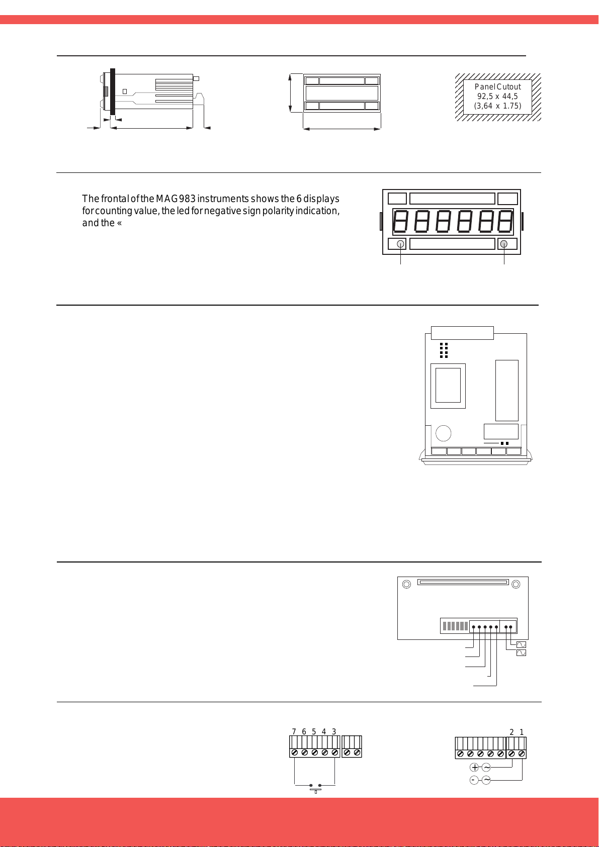
2.- Mechanical Dimensions (mm / inches)___________________________________
2345678901234567
2345678901234567
2345678901234567
Panel Cutout
2345678901234567
2345678901234567
92,5 x 44,5
2345678901234567
2345678901234567
(3,64 x 1.75)
2345678901234567
13
(0,51)
5 max (0,20)
102
(4,02)
15
(0,59)
48
(1,89)
96
(3,78)
3.- Front View__________________________________________________________
The frontal of the MAG983 instruments shows the 6 displays
for counting value, the led for negative sign polarity indication,
and the «RESET» push button. This button can be disabled
acting on jumper L (See section 4.3)
Negative
RESET
Sign LED
4.- Internal Jumpers (Trigger Levels, Antirrebound Filters, Front Reset ):___________
4.1 .- Trigger Levels for NPN, PNP, NAMUR signals
Jumper H,G Closed Jumpers H,G open
Trigger Level LOW Trigger Level HIGH
G
H
J
K
Logical «1» >3.75 Vdc Logical «1» >7.50 Vdc
Logical «0» <1.50 Vdc Logical «0» <5.50 Vdc
4.2 .- Antirrebound Filters .- Jumpers J,K
Closed.- Antirrebound filters at <100 Hz
Open .- Antirrebound filters at <10KHz
Note .- Use filter <100Hz for input type mechanical contact,
in order to filter contact rebounds
Jumper L
4.3. - Frontal Reset.- Jumper L
Closed .- Enables front button for RESET
5.- Rear side view________________________________________________________
The rear side of the instrument shows the terminals for
connecting signals, power of the instrument, and contact for
«RESET», and the jumpers for signal type selection
(Jumpers A,B,C,D,E,F)
Reset
Input2
Input1
Vexc (+10Vdc)
Common
FEDCBA
7 6 5 4 3
2 1
Power
+
-
6.- Power connections and Rearside Reset____________________________________
The «RESET» connection at the
rearside terminal is operated with a
mechanical contact connected at
terminals 7 and 3. Power is connected
at terminals 1 and 2.
FEMA ELECTRÓNICA - Page 3
Connections for
RESET
76543
RESET
Connections for
POWER SUPPLY
21
~~+
-
 Loading...