

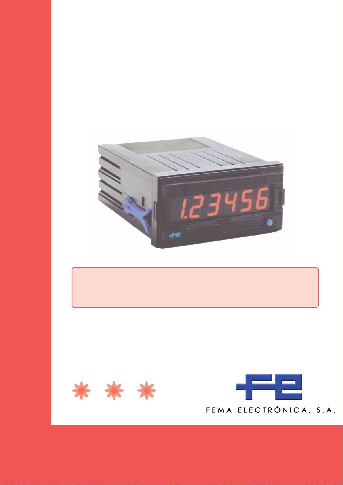
COUNTERS
for IMPULSES
Series MAG983-X
COUNTERS for IMPULSE signals
MAG983-1
MAG983-2
MAG983-3
MAG983-4
IDEAL SOLUTION for impulse counting applications where the operator
has no access to the configuration of the unit. Instruments with scaling
capability, in order to visualize in different units such as units, meters,
accumulated flow, ...
FEMA ELECTRÓNICA
USER’S MANUAL
(HT0695-r050705)
FEMA ELECTRÓNICA - Page 1

User¨s Manual - Series MAG983-X
Series MAG983-X
Impulse COUNTERS
The MAG983-X is a series of impulse counters with 6
digits for panel mounting. The main input channel for
impulse counting is defined as «INPUT1», and the
additional input channel defined as «INPUT2» has a
variable function depending on the model selected. All
units can «RESET» from frontal push button and also
from rearside terminal for mechanical contact.
Model MAG983-1
Impulse counter with Inhibit Control
«INPUT1» Input for impulses
«INPUT2» Control for Inhibit
Note .- «INPUT2» at negative logic, activates inhibit
Model MAG983-3
Impulse counter with Add/Substract inputs
«INPUT1» Impulses to ADD
«INPUT2» Impulses to SUBSTRACT
The reading of the instruments can be scaled activating
scale factors, together with the position of the decimal
point. By default, all units are configured as :
1 impulse = +1
Signal type NPN
Without decimal points
If a different configuration is needed, request your needs
with the order, or see instructions on section 8 for self
configuration.
Model MAG983-2
Impulse counter with Add/Substract control
«INPUT1» Input for impulses
«INPUT2» Control for ADD/SUBSTRACT
Note .- «INPUT2» at negative logic SUBSTRACTS
Model MAG983-4
Impulse counter for Quadrature (Encoder)
«INPUT1» Impulses from encoder CHANNEL-A
«INPUT2» Impulses from encoder CHANNEL-B
0.- Ordering Reference ____________________________________________________
Model Power Signal Type Counting Relation Decimal Point
MAG983
1 230 Vac N PN 1 imp = +1 xxxxxx
2 PNP 1 imp = +2.5 xxxxx.x
3 Namur 1 imp = +0.1 xxx.xxx
4 Pick-Up ...
Mechanical
1.- Technical Data________________________________________________________
DISPLAYS Led 7 segments red color
SEGMENTS 9.9.9.9.9.9
DIGIT HEIGHT 14,2 mm. (0,56")
POLARITY negative counting indicated by LED
READING from 0 to 999999
DECIMAL POINT 6 positions, factory selected
(or see section 8)
INPUT SIGNAL PNP,NPN,Namur,Contact, Pick-Up
Jumper selectable
maximum 28Vdc at input
PICK-UP Data only on «INPUT1»
Sensibility 150 mV peak
Hysteresis 100 mV
Impedance 26.5 Kohms at 60 Hz
Maximum input voltage ±50 Vpp
RESET Contact at rearside terminals
Frontal push button
Vexc OUTPUT +10Vdc (maximum 70 mA)
FREQUENCY maximum up to 10 KHz
MEMORY E2 Prom non volatile
ON/OFF CYCLES 100.000 minimum
DATA RETENTION 10 years minimum
TRIGGER LEVELS Selectable (See section 4)
«0» < 1.50 Vdc or «0» < 5.50 Vdc
«1» > 3.75 Vdc or «1» < 7.50 Vdc
POWER 230 Vac (50 Hz)
CONSUMPTION 3VA
EXTERNAL FUSE 50 mA a t 230 Vac (not incluided)
CONNECTIONS Plug-in screw clamps
WIRE SECTION max. 2.5 mm2 (recommended1mm2)
WORKING TEMP. from 0 to +50 ºC
STORAGE TEMP. from -40 to +70 ºC
RELATIVE HUMIDITY 90 % a 40°C
HOUSING DIN 43700
DIMENSIONS 96 x 48 x 117 mm (3,78 x1,89 x 4,61’’)
PANEL CUTOUT 92,5 x 44,5 mm (3,64 x 1,75‘’)
MATERIAL HOUSING ABS, black color
WEIGHT 310 gr.
FEMA ELECTRÓNICA - Page 2
User¨s Manual - Series MAG983-X
8
8
8
8
8
8
8
8
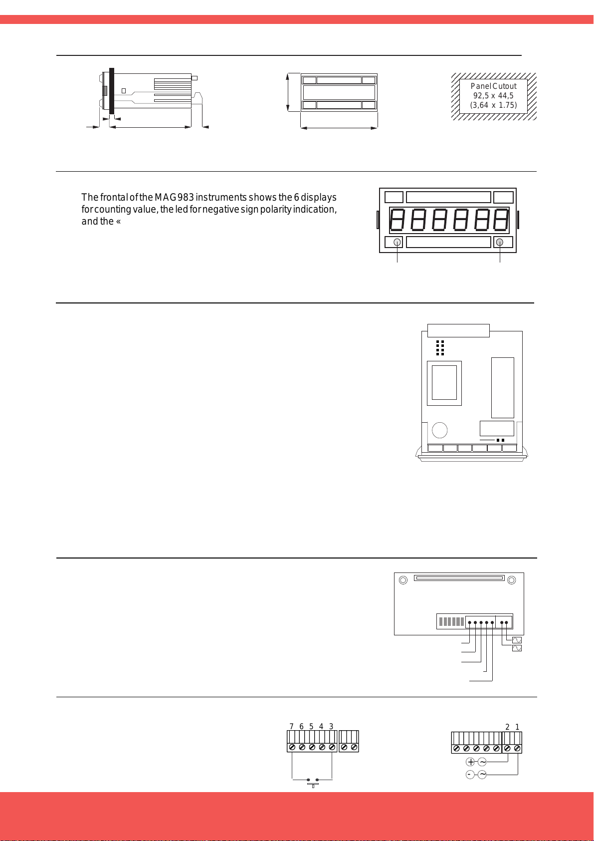
2.- Mechanical Dimensions (mm / inches)___________________________________
2345678901234567
2345678901234567
2345678901234567
Panel Cutout
2345678901234567
2345678901234567
92,5 x 44,5
2345678901234567
2345678901234567
(3,64 x 1.75)
2345678901234567
13
(0,51)
5 max (0,20)
102
(4,02)
15
(0,59)
48
(1,89)
96
(3,78)
3.- Front View__________________________________________________________
The frontal of the MAG983 instruments shows the 6 displays
for counting value, the led for negative sign polarity indication,
and the «RESET» push button. This button can be disabled
acting on jumper L (See section 4.3)
Negative
RESET
Sign LED
4.- Internal Jumpers (Trigger Levels, Antirrebound Filters, Front Reset ):___________
4.1 .- Trigger Levels for NPN, PNP, NAMUR signals
Jumper H,G Closed Jumpers H,G open
Trigger Level LOW Trigger Level HIGH
G
H
J
K
Logical «1» >3.75 Vdc Logical «1» >7.50 Vdc
Logical «0» <1.50 Vdc Logical «0» <5.50 Vdc
4.2 .- Antirrebound Filters .- Jumpers J,K
Closed.- Antirrebound filters at <100 Hz
Open .- Antirrebound filters at <10KHz
Note .- Use filter <100Hz for input type mechanical contact,
in order to filter contact rebounds
Jumper L
4.3. - Frontal Reset.- Jumper L
Closed .- Enables front button for RESET
5.- Rear side view________________________________________________________
The rear side of the instrument shows the terminals for
connecting signals, power of the instrument, and contact for
«RESET», and the jumpers for signal type selection
(Jumpers A,B,C,D,E,F)
Reset
Input2
Input1
Vexc (+10Vdc)
Common
FEDCBA
7 6 5 4 3
2 1
Power
+
-
6.- Power connections and Rearside Reset____________________________________
The «RESET» connection at the
rearside terminal is operated with a
mechanical contact connected at
terminals 7 and 3. Power is connected
at terminals 1 and 2.
FEMA ELECTRÓNICA - Page 3
Connections for
RESET
76543
RESET
Connections for
POWER SUPPLY
21
~~+
-

User¨s Manual - Series MAG983-X
7.- Connections for input signals and Signal Type selection______________________
7.1 .- Sensor Type MECHANICAL CONTACT
Select Jumpers ADF
«INPUT1» terminals 5 (Signal) and 3 (Common)
«INPUT2» terminals 6 (Signal) and 3 (Common)
Note -. close internal jumpers J,K. See section 4.2
MECHANICAL CONTACT
at «INPUT1»
76543
7.2 .- Sensor Type NPN or PNP
NPN .- Jumpers ADF
PNP .- Jumpers ABCDF
«INPUT1» terminals 5 (Signal), 3 (Common) y 4 (Vexc)
«INPUT2» terminals 6 (Signal), 3 (Common) y 4 (Vexc)
7.3 .- Sensor Type NAMUR
Select Jumpers BCDF
«INPUT1» terminals 5 (Vexc), 4 (Signal)
«INPUT2» terminals 6 (Vexc), 4 (Signal)
MECHANICAL CONTACT
at «INPUT2»
SENSOR NPN or PNP
at «INPUT1»
SENSOR NPN or PNP
at «INPUT2»
SENSOR NAMUR
at «INPUT1»
76543
76543
Signal
+10 Vdc
0 Vdc
76543
Signal
+10 Vdc
0 Vdc
76543
Signal
+10 Vdc
7.4 .- Sensor Type PICKUP
Select Jumpers AE
«INPUT1» terminals 5 (Signal) y 3 (Common)
«INPUT2» terminals 6 (Signal) y 3 (Common)
Note .- Input2 will be Mechanical Contact. It can not be configured
for PICK-UP type
SENSOR NAMUR
at «INPUT2»
SENSOR PICK-UP
at «INPUT1»
SENSOR PICK-UP
at «INPUT2»
76543
Señal
76543
Señal
76543
+10 Vdc
0 Vdc
FEMA ELECTRÓNICA - Page 4

User¨s Manual - Series MAG983-X
8.- Introducing how to programm the instrument______________________________
The MAG983 instruments do not have programming keypad accesible to the end user. To modify the configuration
of the instrument, access the internal pins and configure the contacts indicated on «figure 1». These contacts
will allow the activation of the required programming codes.
Example .- To activate code «65 2E» (activation of decimal point at position XXXXX.X) close one after the other
contacts «6», «5», «2» and «E»
Contact 6 Number «6» appears on display 6
Contact 5 Number «5» appears on display 65 1
Together with code «65» appears also the number «1» indicating that code «65»
already has a value of «1», this means, configuration without decimal point
Contact 2 Number «2» replaces number «1» 65 2
Contact E The instrument activates the decimal point XXXX . XX
Note .- the programming codes «1», «2» and «3», are composed of 1 digit only. When closing contact «3» the
display will show a 5 digits number, which is the actual value of the «Scale Factor» (by default its value is
«1.0000»). To modify each one of these 5 digits, close contacts «1» to «5» and once the desired value is on the
display close «E» to validate.
Common
Contact +/Contact 6
Contact 5
Contact 4
Contact 3
Contact 2
Contact 1
Contact E (ENTER)
Figure1 .Connecting the programming contacts
9.- Reset of the Configuration and Default Parameters__________________________
«41 -1E» Reset of the instruments configuration. Activates the default parameters
In order to place this code, close «4», «1», «1», «±» and «E»
± Select «±» to swtich between active instruments. MAG983 units have 2 internal instruments,
a ratemeter and a counter. By default after the activation of a «41 -1» code, the ratemeter remains
activated. Close «±» to activate the counter
Default Parameters
«41 1E» Default Parameters
«42 3E» Default Parameters
«43 1E» «Input1» input, «Input2» inhibit control
«44 1E» «Flanges multiplication» x1
«45 1E» «Multiplication Factor» x1
«46 1E» without Decimal Point
«61 4E» Default Parameters
«62 1E» Default Parameters
«63 1E» Default Parameters
«64 4E» Default Parameters
«65 1E» Default Parameters
«51 2E» «AL1» and «AL2» assigned to Counter
«52 3E» Default Parameters
«53» Default Parameters
«54 3E» Default Parameters
«55» Default Parameters
«56 1E» Special functions. Normal Reset
«66 1E» Default Parameters
«1» 500 Value for memory «AL1»
«2» 1000 Value for memory «AL2»
«3»1.0000«Scale Factor»
FEMA ELECTRÓNICA - Page 5

User¨s Manual - Series MAG983-X
10.- Instrument Selection and Maximum Frequencies__________________________
The Instrument Selection codes define if the instrument will work as impulse add, add/substract, etc, and it
corresponds to the different units of MAG983 available.
«INPUT1» «INPUT2» Max. Frequency Comments
«43 1E» impulses control Inhibit 10 KHz Inhibits at logical state «0»
«43 2E» impulses control Add/Substract 10 KHz Substracts at logical state «0»
«43 3E» imp. Add imp. Substract 4.0 KHZ
«43 4E» Does not apply -----------
«43 5E» Channel AB from bidirectional encoder 5.0 KHz Quadrature signal x1
«43 6E» Channel AB from bidirectional encoder 2.5 KHz Quadrature signal x4
11.- Programming the Multiplicators_________________________________________
«3 » «Scale Factor» is a multiplicator with a value between 0.0000 and 5.9999. By default is 1.0000
«45 1E» «Multiplication Factor» x1 Acts on the displayed value x0.1
«45 2E» «Multiplication Factor» x0,1 and shows counted impulses /10
«45 3E» «Multiplication Factor» x0,01
«45 4E» «Multiplication Factor» x0,001
«44 1E» «Multiplication Flanges» x1 (Counts at down flanges)
«44 2E» «Multiplication Flanges» x2 (Counts at up flanges and down flanges)
Note .- Not compatible with code «43 6E». Reduces maximum frequencies to the half
12.- Decimal Point Position_________________________________________________
«46 1E» 0 Note .- The same codes but with negative, allow
«46 2E» 0.0 visualization of zeroes to the left. For example
«46 3E» 0.00 code «46 -2E» will show 00000.0
«46 4E» 0.000
«46 5E» 0.0000
13.- Specials Functions with the «RESET» and memories «AL1» and «AL2»__________
«56 1E» When pressing «RESET» loads on display 000000
«56 2E» When pressing «RESET» loads on display the value of «AL2» and the impulses substract
«56 3E» Does not apply
«56 4E» Does not apply
«56 5E» When pressing «RESET» loads on display 000000 and when «AL2» value is reached,
display loads 000000
«56 6E» When pressing «RESET» loads on display the value of «AL2» and the impulses substract
When reaching 000000 the value of «AL2» is loaded again and the impulses SUBSTRACT
«1 » Show the value of memory «AL1»
«2 » Show the value of memory «AL2»
To modify the value of the memory «AL1» or «AL2, once loaded on display, use contacts 1,2,3,4,5,6 to modify the
values of digits 1,2,3,4,5,6 and when the desired value is displayed close «E» to apply.
ATTENTION - Límit on the Internal Counter
The MAG983 instrument works with a 23 bits
internal counter (maximum 8.388.608 impulsos can
be counted). If this value is exceeded, the negative
led sign is activated and the display will work in
SUBSTRACT mode. Do a «RESET» of the display in
order to recove functionality. Memory «AL2» can be also
programmed to activate a «RESET» when its value is
reached (see code «56 5E»).
FEMA ELECTRÓNICA - Page 6

User¨s Manual - Series MAG983-X
14.- Security Prescriptions ____________________________________________________
INSTALLATION PRECAUTIONS.- The installation
and use of this unit must be done by qualified
operators. The unit has not power switch, and the
unit has not internal protection fuse, and will start operation as
soon as power is connected. The installation must incorporate an
external main switch with a protection fuse of :
fuse 50 mA (at 230 Vac power)
Also the necessary devices to protect the operator and the process
when using the unit to control a machine or process where injury to
personnel or damage to equipment or process, may occur as a result
of failure of the unit.
SAFETY PRESCRIPTIONS.- The unit has been designed and
tested under UNE 20553 rules and is delivered in good
condition. This manual contains information for electrical
connections. Do not make wiring signal changes or connections when power is applied to the unit. Make signal connections
before power is applied and, is reconnection is required, disconnect
the AC (mains) power before such wiring is attempted. Install the unit
in places with a good ventilation to avoid the excessive heating. And
far from electrical noise source or magnetic field generators such as
power relays, electrical motors, speed controls etc... The unit cannot
be installed in open places. Do not use until the installation is finished.
POWER SUPPLY.- The power supply must be connected to the
adequate terminals (see the connection instructions). The characteristics of the power supply are written on the attached label. Please
make sure that the unit is correctly connected to a power supply of
the correct voltage and frequency. Do not use other power supply
otherwise permanent damage may be caused to the unit. Do not
connect the unit to power sources heavily loaded or to circuits which
power loads in cycle ON-OFF or circuits with power inductive loads.
SIGNAL WIRING.- Certain considerations must be given when install
the signal input and control wires. Long wires can act like antennas
and introduce electrical noise to the unit, therefore :
A.- Do not install the signal input or control wires in the same
conduit with power lines, heaters, solenoids, SCR controls etc....and
always far from these elements.
B.- When shielded wires are used, connect the shield to the
common terminal and leave unconnected the other end of the shield
and do not connect to the machine ground.
EXCITATION VOLTAGE.- The unit supplies excitation voltage for sensors, at terminals 3 and 4. Do
not connect these terminals to external power
supply, permanent damages may result to the unit.
SAFETY CONSIDERATIONS .- Before starting any operation of
adjustment, replacement, maintenance or repair, the unit must be
disconnected from the power supply. Keep the unit clean , to assure
good functioning and performance. To prevent electrical or fire
hazard, do not expose the unit to excessive moisture. Do not operate
the unit in the presence of flammable gases or fumes, such as
environment constitutes a definite safety hazard. The unit is designed to be mounted in a metal panel.
If the unit shows signs of damage, or is not able to show the expected
measures, or has been stored in a bad conditions or a protection
failure can occur, then do not attempt to operate and keep the unit
out of service.
IN CASE OF FIRE
1.- Disconnect the unit from the power supply.
2.- Give the alarm according to the local rules.
3.- Switch off all the air conditioning devices.
4.- Attack the fire with carbonic snow, do not use water in any case.
WARNING : In closed areas do not use sys-
tems with vaporized liquids.
CONNECTIONS
All wiring connections are made using push-in cable connectors.
There is a separate connector block for power supply, input signals
and each relay output. Please make sure that each connector block
is connected on the adequate place.
PANEL MOUNTING.- The instrument size case is 1/8 DIN. The
internal electronic circuit can be inserted or removed by the front part
and is held on to the case by the two lateral lugs, which must be put
in their corresponding holes placed on each case side. Verify that
the panel cut-out is correctly according to the dimensions indicated
with a minimum depth of 135 mm. (5.31"). Install the fixation clips of
blue colour in the lateral guides of the unit by its rear part and then
slide and press them firmly against the panel, until the unit is totally
hold on.
15.- Declaration of Conformity__________________________________________________
DECLARA TION OF CONFORMITY
Manufacturer.- FEMA ELECTRÓNICA, S.A.
Address .- Pol. Ind. Santiga - Altimira 14 (T14 - N2)
E-08210 Barberà - BARCELONA
ESPAÑA - SPAIN
Conforming products
Model .- MAG983-1, MAG983-2, MAG983-3, MAG983-4
We hereby declare that the above products conform to the
essential protection requirements of Directives and
Harmonised Standards stated below.
Signed .- D. Juncà
Position.- Quality Manager
Place .- Barberà, 2005
FEMA ELECTRÓNICA - Page 7
DIRECTIVES
EUROPEAN DIRECTIVE FOR LOW VOLTAGE D73/23/CEE AMENDED BY D93/
68/CEE. Equipments powered from 50 to 1000 Vac. and / or from 75 to 1500 Vdc.
ELECTROTECHNICAL REGULATION FOR LOW VOLTAGE (RBT) ITC21,
ITC29, ITC35. Equipments with power supply lower than 50 Vac and/or 75 Vdc.
EUROPEAN DIRECTIVE FOR ELECTROMAGNETIC COMPATIBILITY D89/
336/CEE AMENDED BY D93/68/CEE
STANDARDS
IMMUNITY UNE EN 50082-1 (1998)
EMISSIONS UNE EN 50081-1 (1994)
ELECTRICAL SAFETY UNE EN 61010-1 (1996)
UNE EN 60204-1 (1997)

more pr oducts
Programmable
Panel Meters
Standard
Panel Meters
Isolated Transmitters
Miniature
Panel Meters
Large DisplaysSignal Converters &
Large Displays
for TIME
www.fema.es
ELECTRONIC INSTRUMENTATION FOR INDUSTRY
FEMA ELECTRÓNICA, S.A.
Pol. Ind. Santiga - Altimira 14 (T14 - N2)
E-08210 Barberà - BARCELONA
ESPAÑA - SPAIN
Tel. (+34) 93.729.6004 - www.fema.es
Fax (+34) 93.729.6003 - info@fema.es
FEMA ELECTRÓNICA - Page 8
 Loading...