

Fema M40 Series, M40-P User Manual
Model M40-P for process signals
( ±20mA and ±10Vdc)
Series M40
Panel meter for process signals in mA and Vdc. Accepts both active and passive
signals, monopolar and bipolar, from 2 and 3 wire transducers. Housing 96x48mm DIN
standard. Display in 4 or 5 digits. Provides excitation voltage for transducers. Segment
linearization, maximum and minimum display memory, scalable reading, lters, steps,
signal autocorrection, “measure” function, peak&hold, alarms with double setpoints, 5
levels of brightness, ... Universal AC and DC power modules and up to 3 modules for
signal retransmission and control.
Panel Meters
FEMA ELECTRÓNICA
USER’S MANUAL
(2145R00)
Panel meter 96x48mm
Datasheet
Sales: +44 (0) 1273 570 220 Website: www.amplicon.com Email: sales@amplicon.com
IT and Instrumentation for industry Amplicon.com
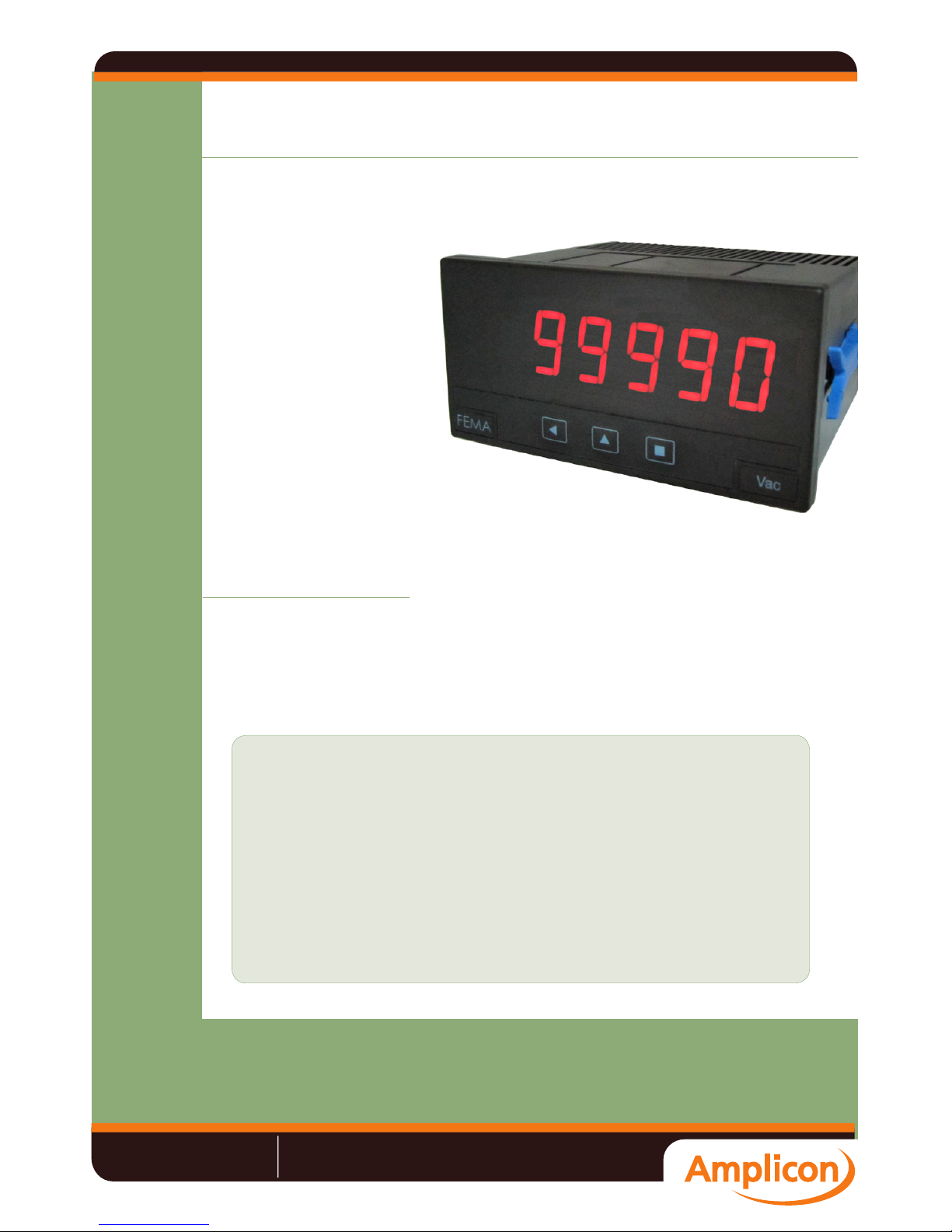
Meter M40-P
Panel meter 96x48mm size for process signals
Panel meter for process signals in mA and Vdc, active and
passive, monopolar and bipolar, from 2 or 3 wire transducers.
Provides +15V (max. 40mA) excitation voltage to power-up
the transducer when needed. Scalable reading. 10 segment
linearization.
Instrument with 96x48mm standard DIN size. Resolution 4
digits plus negative sign (“-9999”) or 5 digits with negative
sign with last digit xed to zero (“99990”, with menu function
“Right Zero”).
Management for up to 4 alarms with 1 or 2 setpoints each,
with hysteresis and delays. Provides memory for maximum
and minimum, left zeros, display on selectable steps, xed
digits, recursive display lter, password, brightness control,
“measure” function (visualizes input signal without scaling),
offset and signal high autocorrection (assigns the actual
signal to the low or high reading), “peak&hold” function and
password.
Power options with universal AC and DC ranges, and space
for 2* additional control and/or signal retransmission modules
(*soon 3 modules).
For measurements in CAT-II and for environments with degree of pollution 1 and 2 without condensation. Standard IP54
front protection, with optional upgrade to IP65 protection.
Connections via plug-in screw terminals and conguration
via three front push-buttons. For application on industrial
environments.
This instrument has been designed and veried according to the 61010-1
CE security regulation, and is designed for applications on industrial environments. See the “CE Declaration of Conformity” further in this document for
information on the category of measure and the degree of pollution levels
that apply.
Installation of this instrument must be performed by qualied personnel
only. This manual contains the appropriate information for the installation.
Using the instrument in ways not specied by the manufacturer may lead
to a reduction on the specied protection level. Disconnect the instrument
from power before starting any maintenance and / or installation action.
Risk of electrical shock. Instrument terminals can be connected
to dangerous voltage.
Instrument protected with double isolation. No earth connection
required.
The instrument does not have a general switch and will start operation as
soon as power is connected. The instrument does not have protection fuse,
the fuse must be added during installation.
The instrument is designed to be panel mounted. An appropriate ventilation
of the instrument must be assured. Do not expose the instrument to excess
of humidity. Maintain clean by using a humid rag and do NOT use abrasive
products such as alcohols, solvents, etc.
General recommendations for electrical installations apply, and for proper
functionality we recommend : if possible, install the instrument far from
electrical noise or magnetic eld generators such as power relays, electrical motors, speed variators, ... If possible, do not install along the same
conduits power cables (power, motor controllers, electrovalves, ...) together
with signal and/or control cables.
Before proceeding to the power connection, verify that the voltage level
available matches the power levels indicated in the label on the instrument.
In case of re, disconnect the instrument from the power line, re alarm
according to local rules, disconnect the air conditioning, attack re with
carbonic snow, never with water.
Instrument is in conformity with CE rules and regulations. See
“CE Declaration of Conformity” further in this document.
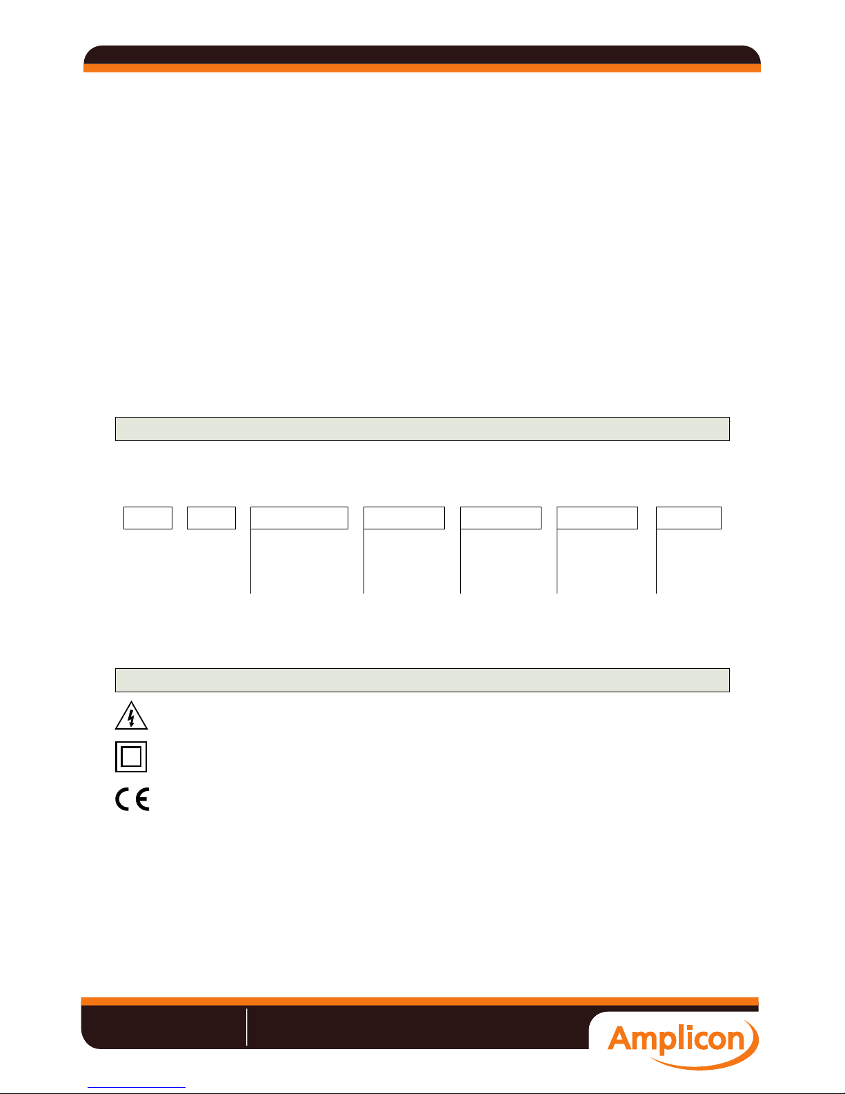
Order Reference
Precautions on installation
M40 P H
Model Power
-H
(85-265 Vac/dc)
-L (11-60 Vdc
and 24/48 Vac)
- - - ---
Option1
-R1
(1 relay)
-AO (Analogue output)
-(empty)
- ---
Others
-65
(IP65)
-(empty)
---
Option2
-R1
(1 relay)
-AO (Analogue output)
-(empty)
- ---
Option3*
*Available soon
-
Datasheet
Sales: +44 (0) 1273 570 220 Website: www.amplicon.com Email: sales@amplicon.com
IT and Instrumentation for industry Amplicon.com
Passive voltage signal 0/10Vdc / ±10Vdc
Common
Vexc
Signal
Active voltage signal 0/10Vdc / ±10Vdc
Common
Signal
Active current loop 4/20mA / ±20mA
Common
Passive current loop 4/20mA / ±20mA
Vexc
Signal
Earth connection - Although a terminal is offered for earth connection, the
connection is optional. The instrument does not need this connection for
correct functioning nor for compliance with the security regulations.
Fuse - To comply with security regulation 61010-1, add to the power line
a protection fuse acting as disconnection element, easily accessible to the
operator and identied as a protection device.
Power “H” fuse 250mA time-lag
Power “L” fuse 400mA time-lag
Signal
Current
generator
2 Wire
transducer
Voltage
generator
3 Wire
transducer
Front View
Rear View
Signal Connections
Power Connections
Button UP
Logo
Alarms
UnitsButton SQButton LE
PowerSignal
Option1
Option2
Jumpers 45
Option3*
~
~
+
-
8 9 0
123
4 5
Jumper 5 closed
123
4 5
Jumper 5 closed
123
4 5
Jumper 4 closed
123
4 5
Jumper 4 closed
*available soon
Datasheet
Sales: +44 (0) 1273 570 220 Website: www.amplicon.com Email: sales@amplicon.com
IT and Instrumentation for industry Amplicon.com
 Loading...