

Felton Feltonmix U, Feltonmix H, Feltonmix E Installation Manual
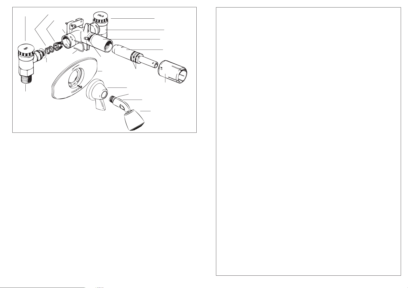
Red Knob ‘HOT’
Compression Spring
Shut-off Seals
Clip
Groove
Blue Knob ‘COLD’
ISOLATOR
Feltonmix
Stainless
Steel Clip
Filters
Isolator
O-Ring
Brass Nipple
SERVICE NOTES
To Replace Seals and Springs
A rubber shut-off seal and spring is fi tted in each
of the two inlets of the valve body and two O-ring
seals fi tted to the rotor located inside the valve
body.
1. Unscrew shower head and stem from valve
body.
2. Using both hands support the handle top and
bottom and withdraw from valve body.
3. Remove wallplate by unscrewing the two
1
⁄
x 7 fi xing screws.
1
8
4. Turn off water supply at either the mains or
the shower mixer isolators.
5. Gently prise stainless steel retaining clips on
valve body outwards with screwdriver and
remove clips completely. Pull isolators clear
of valve body.
6. Unscrew mixer retaining screws and remove
mixer from wall.
7. Remove grub screw from control sleeve.
8. Withdraw rotor from body using a suitable
tool through cross hole in rotor.
9. Using seal extractor tool supplied with the
replacement seal pack, insert end marked
'REMOVE' fully into hole in centre of seal
and withdraw seal and spring.
240613DT
Use only GENUINE FELTONMIX Replacement Parts
MIXER BODY
Rotor
Grub Screw
Wallplate
10.
11. Fit seal in inlet bore with turning motion until
12. Discard O-Ring seals on rotor. Replace with
13. Discard isolator O-Rings and fi t new O-Rings
14. Re-assemble in reverse manner. Insert rotor
Filters
Each isolator is fi tted with a fi lter. These fi lters can
be easily prised out, cleaned and snapped back
into place.
Rotor O-Ring Seals
Handle
Shower Stem O-Ring
Fit blade of seal extractor tool end marked
'REPLACE' into slots in bore of new seal and
spring.
lugs on seal engage in slots in bore of inlet.
Push fully home.
new O-Ring seals.
supplied.
in body. Fit isolators to mixer body. Insert
stainless steel retaining clips through slots
In valve body and press fully home
Control Sleeve
Shower Head Stem
Shower Head
The Perfect Shower Every Time
SHOWER MIXING VALVES
Felton Industries Ltd warrant to the purchaser of this shower mixer
that it is free from defects in materials and workmanship. Accordingly
we undertake to repair or replace and part which we are satisfi ed is
defective for up to fi ve years after installation date. This warranty is
valid only when the mixer is installed by a qualifi ed plumber, to the
following instructions.
Felton Industries Limited is an IS09002 Registered Supplier, and
Feltonmix
AS/NZS 3718:2005, Licence No. WMKA25208 and New Zealand
Standard 4611: 1982, Licence No. 2491.
Three models are available to suit different conditions. Filters are fi tted
to protect parts from damage caused by water born particles. Removal
of these fi lters may void the warranty.
The maximum hot water temperature should not exceed 80ºC
Feltonmix
For use on unequal supply pressures. Mains pressure cold i.e.
supplies from 150 kPa to maximum 500kPa ; low pressure hot i.e.
minimum of 20 kPa to maximum 150 kPa fl ow pressure.
Feltonmix
For use on equal high supply pressures. Mains pressure hot and cold
i.e. supplies from 150 kPa to maximum 500kPa fl ow pressure.
Feltonmix
For use on equal low supply pressures. Hot and cold supply from
minimum 20 kPa to maximum 150 kPa.
Note: A pressure reducing valve in compliance with AS 1357 may
need to be fi tted to maintain supply pressure below 500 kPa.
®
shower valves are manufactured to WaterMark standard
®
Type U - Blue Rotor.
®
Type H - Pink Rotor.
®
Type E - Green Rotor.
Installation Instructions
45 mm
from back
of mixer
to front of
shower
wall Lining.
Warning:
Do not overtighten. Light pressure is suffi cient
to clamp the wallplate fi rmly.
5. Rotate slotted sleeve on valve body
(projecting from central hole of wallplate
anticlockwise and fi t handle to sleeve,
locating a
t the 4 o’clock position. Handle
should recess into the wallplate and match
its contours. Ensure that handle has about
10 mm of engagement.
64 mm
Height
of
recess.
1. Provide a stud or other suitable fi xing in the
shower wall on which to mount the shower valve
Shower head at about eye level (between 1.5 and
1.8 metres) is a good guide. Ensure distance from
mounting face to front of wall lining is 45mm.
2. Flush out pipework. Mount shower valve
assembly and secure with two wood screws
provided. It is important that the pipes which are
now connected directly to the isolator valves on
each side of the shower valve assembly line up
correctly with the isolators and do not place any
unnecessary strain on the valve assembly. Ensure
isolators are open, (turn anticlockwise).
Do not apply heat to pipes connected to the mixer
as internal damage may occur.
Note: When tightening crox nuts it is important to
hold the hexagon face to prevent any strain on the
isolator. Do not attempt to tighten or rem
the brass nipple from the isolator. This has
been installed with correct pre-loading at the
factory and any alteration may cause damage
to the isolator.
3. Cut an access hole in the wallboard to suit the
shape of the wallplate using the template provided.
4. Position the wallplate over the valve outlet and
fi t the two 1
wallplate slot and into the valve body lugs. Tighten
screws alternately until wallplate is fi rmly clamped
to the wall.
FELTONMIX® Shower Valves
Types U, E and H
1
/8 x 7 screws provided through each
6. Screw showerhead into valve assembly
until full home. If necessary unscrew the
showerhead part of a turn to bring it to the
correct position. The O-ring seal fi tted to the
showerhead stem will ensure a watertight
seal. Tape or hemp on the thread is not
necessary or desirable.
7. CHECK OPERATION. When installed check
that the handle swins from right to left from
OFF to HOT. Total movement is about 130°.
ove
TROUBLE SHOOTING
Insuffi cient Water Flow:
Check that the correct model (Type U,
Type E or Type H) has been installed for
the supply conditions. Check fi lters for
foreign
matter.
Insuffi cient Hot Water:
Check that isolators are fully open
(unscrewed anticlockwise) Check that
suffi cient water pressure is reaching the
valve. A minimum of 20 kPa (3 p.s.i.) fl ow
pressure is recommended.
Inadequate hot water temperature and/or
fl ow may also be experienced if a
To protect your investment, use only Genuine Feltonmix Spare Parts. Substitutes
may damage the Feltonmix product. Authorised parts carry the description
GENUINE SPARE PARTS MANUFACTURED BY FELTONMIX LTD, AUCKLAND, N.Z.
tempering valve is fi tted and is not
installed strictly in accordance with the
manufacturer’s instructions.
Valve does not shut off properly:
Check seals.
Water leaks from behind handle:
If water is leaking from under slotted
sleeve when shower is on it will be
necessary to replace O-ring seals on rotor.
(see a/so Service Notes)
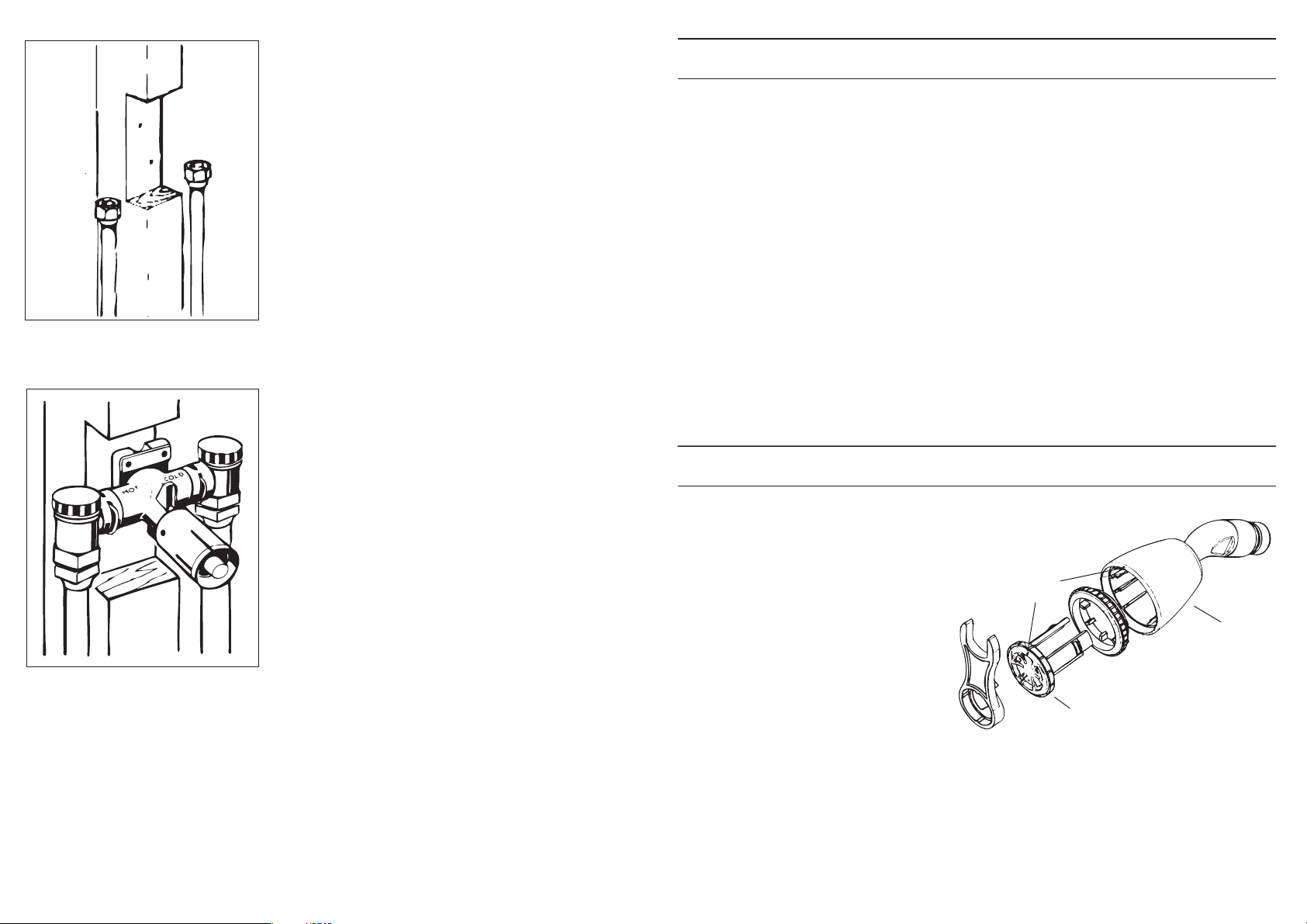
SHOWER HEAD
Your Feltonmix shower head is manufactured
from self-cleaning plastic materials and cleaning
with a soft nylon brush and bathroom cleaners is
usually suffi cient.
If dismantling is required, insert the two leg’s
of the Feltonmix spanner into the face
of the rose. Turn the rose approximately
thirty degrees and withdraw it from the
shower head body.
When assembling ensure that the sharp
outer edge of the soft spray ring is
located at the front edge of its support
ring. Align the assembly pips on the front face
of the rose and lip of the body. Push them together
until they click twice.
Manufac
tured by
FELTON INDUSTRIES LTD
Freephone 0800 PH FELTON (0800 743 358)
Free Fax 0800 FAX FELTON (0800 329 335)
www.felton.co.nz
Assembly
pips
Body
Rose
 Loading...