


Z & ZW Owner’s Manual

Felt Z & ZW Internal Routing Manual
This manual is not intended as a comprehensive use,
service, repair or maintenance manual. Please see your
dealer for all service, repairs or maintenance. Your dealer
may also be able to refer you to classes, clinics or books
on bicycle use, service, repair or maintenance.
Note:
Part II Z & ZW Brake Routing Instruction
Pg. 8-11
. . . . . .
Part I Z & ZW Mechanical Cable Instruction
Pg. 1-7
. . . .
Part III Z & ZW Electronic Wiring Instruction
Pg. 13-19
. . . . .
-2-
1. Mousetail Ferrule
2. Cable Bottom Bracket Cable Guide
3. Brake Cable Housing
4. Front Derailleur Grommet
5. Cable Housing Stop (x4)
6. Hydrolic Brake Grommet
7. Shifter Cable (x2)
8. Brake Cable (x2)
Z & ZW Small Parts
Mechanical Cable & Brake Instruction
1 4
253 6 7 8
-1-

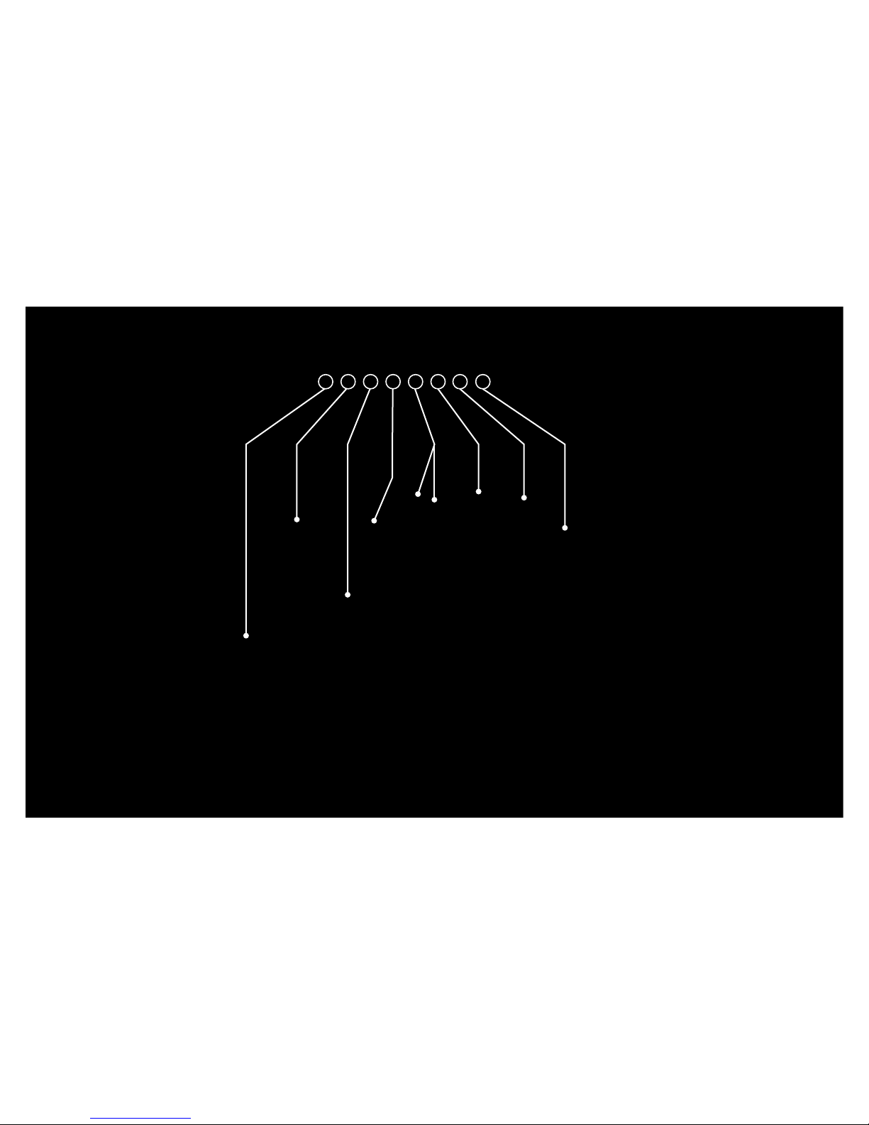
Rear Brake Cable to Brake Lever
Rear Derailleur Cable to Shifter
Front Derailleur Cable to Shifter
Z & ZW Mechanical Cable Internal Routing Road Map
-2-

Thread Front Derailleur Shifter Cable through the shifter and
into cable housing until the head of the shifter cable is seated
correctly in shifter. (depending on your shifter, may look
different than the one pictured)
Step 1
b.
a. Feed Front Derailleur Cable into
Mousetail Ferrule and downtube via
Cable Stop as pictured. Pull cable
taut as it exits the bottom bracket hole.
b. The grommet on the end of the
cable housing should fit snugly
into the Cable Stop.
Step 2
-3-

Front Derailleur Cable is shown exiting
the bottom bracket hole.
Step 3
Repeat steps 1 and 2,
routing the Rear Derailleur
Cable through the right
shifter, cable housing,
though the Cable Stop
and out the bottom
bracket hole.
Step 4
-4-

Slide the mousetail over the Front Derailleur Cable until at least
2” of cable is exposed. Pull both cables to ensure tautness and
confirm they cross over each other in the downtube, but do not
touch each other, or shifting will be compromised.
b. Route Front Derailleur Cable through small bottom bracket
hole and out Front Derailleur Grommet Hole as pictured below.
c. Insert Bottom Bracket Cable Guide as pictured
below. Align with frame and press until it snaps into
place. The Front Derailleur Cable should fit easily in the
channel on the non-drive side of the frame. The Rear
Derailleur Cable should fit easily into the channel on
the drive-side of the frame.
Note: if Front Derailleur
Grommet is installed, remove it
before attempting to route
Front Derailleur Cable.
Step 5
-5-

a. Take cable housing and apply a ferrule
to each end. Fit one end into the chainstay
cable housing mount and route Rear
Derailleur Cable through as pictured.
b. Locate the eyelet on the rear
derailleur and route Rear Derailleur
Cable though and fit Ferruled cable
housing into the eyelet as pictured.
c. Tension and tighten Rear Derailleur
Cable in the tension bolt assembly as
shown.
Step 6
-6-

a. If necessary, slide mousetail into place; about
1” should extend through the Front Derailleur
Grommet Hole as shown. If Mousetail is too
long, trim Mousetail.
b. Slide the Front Derailleur Grommet over
the Front Derailleur Cable and press into Front
Derailleur Grommet Hole as shown.
Step 6
c. Mount the Front Derailleur if needed. While
under tension, reattach the Front Derailleur
Shifter Cable to the Front Derailleur.
-7-

Prior to routing the rear brake, you’ll want to
remove the Top Tube Cable Stop near the seat
tube.
Step 7 Rear Brake Routing
Place the Top Tube Cable Stop and 2mm bolt
aside to be in stalled after routing the rear brake
cable.
-8-

a. Route the Rear Brake Cable into the Top Tube
Cable Stop nearest to the frame’s head tube as
pictured.
* If using hydraulic brakes, be sure to replace the Cable
Housing Stop with a press-fit silicone Hydraulic Brake
Housing Stop before routing Hydraulic Brake Housing.
Step 8
-9-

b. Feed cable through the top
tube until cable exits rear top tube
grommet nearest to the seat tube.
c. Replace the top tube grommet
and tighten the 2mm screw to
secure in place as shown.
Step 9
d. Slide the piece of Rear Brake
Cable housing (ferrule side) into
the top tube grommet as shown.
e. Route the Rear Brake Cable
into the rear brake tension bolt as
shown and attach cable to brake.
-10-

a. Insert brake cable into brake lever and
route through cable housing. Pull taught
until cable head is firmly seated in the
shifter lever.
Step 10 Front Brake Cable Installation
b. Thread brake cable into Front Brake
Tension Bolt. Exposed brake cable housing
should fit into Front Brake Tension Bolt.
c. Pull cable to tension and attach to front
brake as shown.
-11-

-12-

1 4
253 6 7 8
5. Brake Cable Housing Stop
6. Brake Cable Housing Stop Screw
7. Small Di2 Grommet
8. *Shimano Di2 Wires
1. Bottom Bracket Grommet
2. *Junction B
3. Di2 Wire Grommet
4. Frame Grommet Plug
*not included with frame
Z & ZW Small Parts
Electronic Wiring Instruction
-13-

Battery Cable to Junction
External Battery (if applicable) Di2 Junction Box B
Rear Derailleur Cable to Junction
Front Derailleur Cable to Junction Downtube Cable Brain to Junction
Z & ZW Electronic Wire Routing Road Map
*
-14-

a. Route the wire down thruogh the
top tube wire-endtry point, through
the downtube and out the bottom
bracket as pictured.
Step 1
Shifter Junction Wire
Tip: to make routing easier, tape the
end of the wire to the end of a piece of
brake cable (as a steel cable is easier
to route than a wire or housing). Once
cable is visible through exit hole, pull
through and remove tape.
Brake Cable
Electronic Wire
-15-

Route the wire, entering the small hole
located under the front derailleur mount
and out the hole under the bottom
bracket as pictured. Press-fit the Front
Derailleur Grommet (A) into the hole
to prevent Di2 wire from falling into the
frame.
Front Derailleur Wire
Step 2
(A)
b. If needed, attach front derailleur
and plug in Rear Derailleur Wire.
and plug in Rear Derailleur Wire.
-16-

a. Route the rear derailleur
wire through the hole in the
drive-side dropout, through the
chainstay and out the wire-exit
hole under the bottom bracket
as pictured.
b. If needed, attach rear
derailleur and plug in Rear
Derailleur Wire.
Rear Derailleur Wire
Step 3
-17-

Front
Rear
1
2
3
4
a. Plug front and rear derailleur wires (1&2) into
junction box (Rear).
Plug battery wire (3) and shifter wire (4) into
junction box (Front).
b. After, fit the connected Di2 Junction B into
the hole in the bottom bracket and plug with
supplied bottom bracket plug as pictured.
Plug Di2 wire into battery mount.
Junction B
Step 5
-18-

A B C
Step 8
Wire Grommets
Rear Derailleur Grommet Front Derailleur Grommet Downtube Grommet
a. Press in any remaining
grommets. Refer to below
images for placement.
b. If not already done,
connect wires to derailleurs
and Junction B.
A
B
C
-19-

Felt Racing, LLC
12 Chrysler
Irvine, CA 92618
www.feltbicycles.com
Industriestr. 39
26188 Edewecht
Germany
 Loading...