


VR SERIES
TECHNICAL
MANUAL
1
VR SERIES
Congratulations on purchasing a VR Series. As with all of our
bikes and components, our aim is to provide the rider with the
best product and riding experience. Read this manual supplement
thoroughly, as it is designed to help you set your bike up correctly,
and care for it.
For further information, visit:
FELTBICYCLES.COM
INTRODUCTION
CONTENTS
INTRODUCTION
Geometry ................................................................................................. 2
SETUP
Head Tube Cable Guides .......................................................................... 3
Front Brake Cable/Hose Routing............................................................... 4
1x11 Full Housing Cable/Hose Routing ..................................................... 5
2x11 Di2 Cable/Hose Routing ................................................................... 6
2x11 Mechanical Cable/Hose Routing .......................................................7
Bottom Bracket Cable Guide Routing ................................................... 8 -13
Grommet Map ................................................................................... 14-15
CONTACT INFORMATION
Contact................................................................................................... 16
3
2
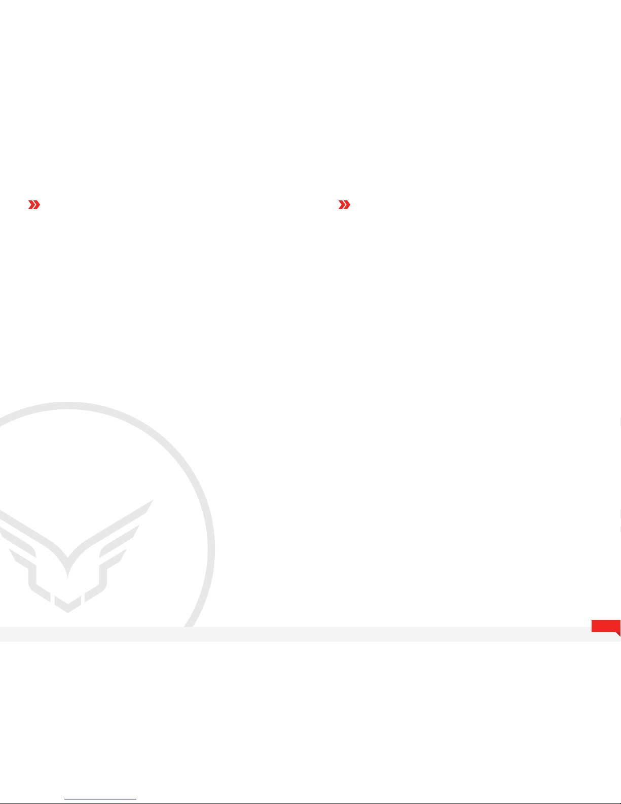
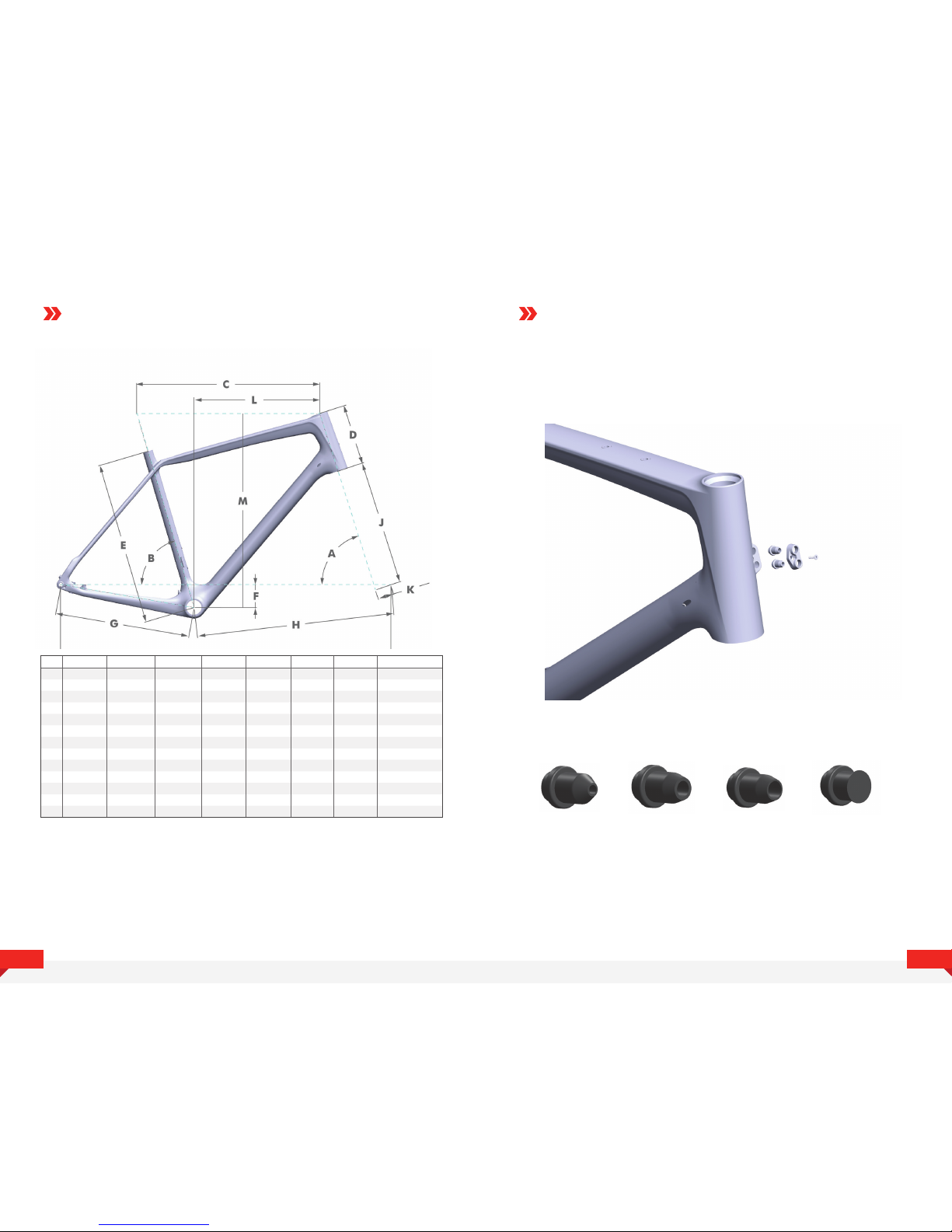
GEOMETRY HEAD TUBE CABLE GUIDES
The head tube cable guides contain rubber reducers for all cable sizes
that are interchangeable and can be arranged to fit each rider's setup
and personal preferences.
Di2 (2mm) Shift (4mm) Brake (5mm) Blank Plug
A
B
C
D
E
F
G
H
I
J
K
L
M
43
70.3
75.3
495
115
410
72
412
576
977
380
50
52
521
47
71.3
74.7
510
130
430
72
412
580
981
380
50
52
539
51
72
74.5
525
145
450
70
415
584
989
380
50
50
555
54
72.5
74
545
165
480
70
415
595
1000
380
45
50
576
Size
Head Tube Angle
Seat Tube Angle
Top Tube Horizontal
Head Tube
Seat Tube
BB Drop
Chain stay
Front Center
Wheelbase
Fork Length
Fork Oset
Reach
Stack
56
72.5
73.5
563
185
500
70
415
608
1013
380
45
50
595
58
72.5
73
580
205
520
70
417
620
1027
380
45
50
614
61
72.5
73
595
225
550
70
417
635
1042
380
45
50
633

1x11 FULL HOUSING
5
4
ROUTINGROUTING
FRONT BRAKE
It is best to route the cable from the bottom up. Begin by
inserting the end of the cable into the lower hole, feeding
the cable through the fork blade toward the upper hole.
IMPORTANT
To allow for full range of
handlebar movement, it’s
important to always route
the front brake cable on the
outside of the the cables
exiting the ports found on
the headtube. (as shown)

Di2 2x 11
ROUTING
2x11 MECHANICAL
7
6
ROUTING

ROUTING
BOTTOM BR ACKET
CABLE GUIDE
ROUTING
BOTTOM BR ACKET
CABLE GUIDE
9
8
Thread the supplied cable liners over each cable. This will keep the cable liners
from crimping and creating friction during the routing process.
Start by threading the front derailleur cable through the port found on the non-drive
side of the downtube. The cable will exit at the port found on the underside of the
bottom bracket.
Now replicate this step on the drive side for the rear derailleur cable. This cable will
also be exiting the port found on the underside of the bottom bracket.
Once both cables are exiting the port found on the underside of the bottom bracket,
you want make sure they are running parallel to each other before crossing them
over each other a single time.

ROUTING
BOTTOM BR ACKET
CABLE GUIDE
ROUTING
BOTTOM BR ACKET
CABLE GUIDE
11
10
Once the cables have been crossed over each other once, carefully insert the
cable guide while making sure not to pinch the cables. The front derailleur cable
will run in the slot on the non-drive side, while the rear derailleur cable will run
along the drive side.
Once the cables are place in their proper slot, press the plastic cable guide into the
frame to until the guide sits flush with the underside of the bottom bracket. If you find
any resistance, make sure the cables aren’t being pinched.
Take the front derailleur cable and thread through and under the circled bridge in
the cable guide. Leave a loop of excess cable on the end closest to the headtube.
You will now take the front derailleur cable and thread it into the circled hole, and
out the front derailleur cable port found directly parallel to it on the top of the
bottom bracket shell.

ROUTING
BOTTOM BR ACKET
CABLE GUIDE
ROUTING
BOTTOM BR ACKET
CABLE GUIDE
13
12
Once the cable has been successfully threaded through, pull it tight while making
sure the remaining cable doesn’t crimp while the loops disappear as the cable is
pulled through.
Now locate the rear derailleur cable that has been previously threaded through and
pull a healthy amount of cable out for the next step.
While keeping a small loop in the cable on outside of the bottom bracket guide,
begin to thread the cable through the circled hole and into the chainstays. If you find
any resistance during this step, twisting the cable can help it find it’s way through the
chainstay cavity.
If the previous step was done properly, the derailleur cable should exit the rear cable
port where you can then pull the cable tight. At this point, your cables have been
successfully routed.

GROMMET MAP GROMMET MAP
CONT.
15
14

16
CONTACT
INFORMATION
Felt Racing, LLC
12 Chrysler
Irvine, CA 92618
USA
WWW.FELTBICYCLES.COM
Felt GmbH
Industriestr. 39
26188 Edewecht
Germany
 Loading...