

Page 1

CONTENTS:
2. BAYONET FORK INSTALLATION
4. AEROBAR INSTALLATION
5. RISER, PAD, & EXTENSION INSTALLATION
8. SEATPOST INSTALLATION
9. SEATPOST HEAD & SADDLE INSTALLATION
11. “TRAIN” CRANK INSTALLATION
13. “RACE” CRANK INSTALLATION
15.
REAR WHEEL INSTALLATION
17.
FRONT WHEEL INSTALLATION
18. COG & LOCKRING INSTALLATION
1
Page 2
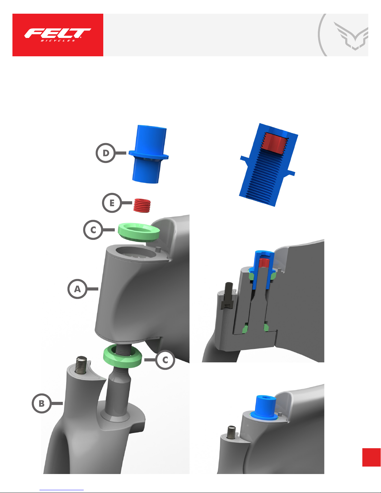
BAYONET FORK INSTALLATION
PARTS:
Frame
A.
Fork
B.
2 x Bayonet 3 (“B3”) 19mm headset bearings
C.
1 x Bayonet 3 (“B3”) headset tension nut, 8mm
D.
1 x Bayonet 3 (“B3”) headset set screw, 5mm
E.
STEPS:
1. Place one (1) B3 headset bearing onto integrated fork crown race.
2. Insert fork steerer into frame.
3. Place one (1) B3 headset bearing into frame.
Twist B3 tension nut onto steerer.
4.
5. Twist fork to ensure tension nut is not over tightened.
Using a torque wrench, tighten B3 headset set screw to 6-8 Nm
6.
REQUIRED TOOLS:
8mm Allen key
-
5mm Allen key
-
Torque wrench
-
2
Page 3
BAYONET FORK INSTALLATION
3
Page 4
AEROBAR INSTALLATION
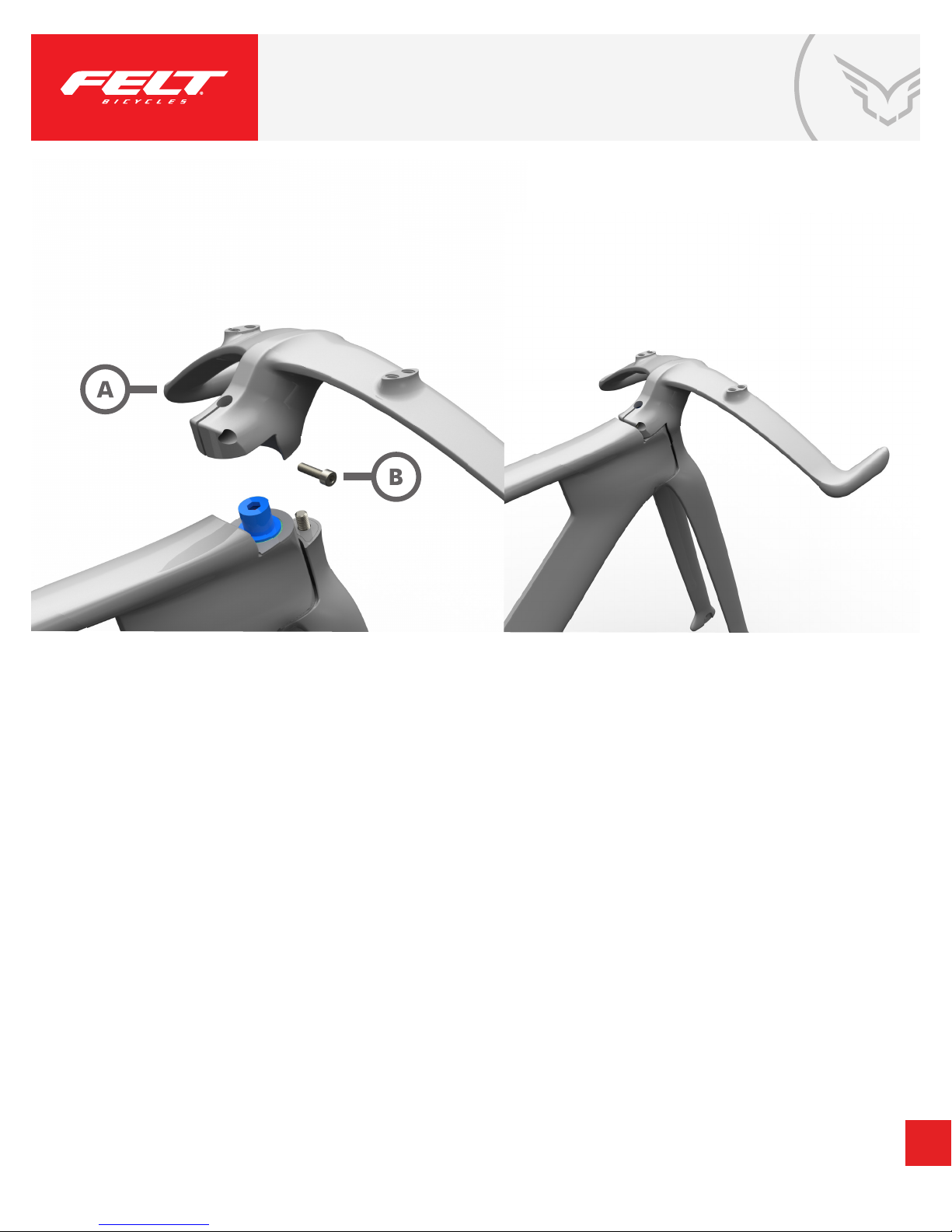
PARTS:
Aerobar
A.
Frame
B.
STEPS:
1. Use 4mm Allen key to loosen M5x18 socket head cap screw on stem.
2. Position Aerobar stem onto B3 tension nut, and align fork bolt to stem.
3. While applying light, downward pressure on the stem, use a torque wrench
with a 3/8” drive, long hex, 6mm socket bit to tighten fork bolt to 10-12 Nm.
REQUIRED TOOLS:
3/8” drive, long hex, 6mm socket bit
-
4mm Allen key
-
Torque wrench
-
4
Page 5
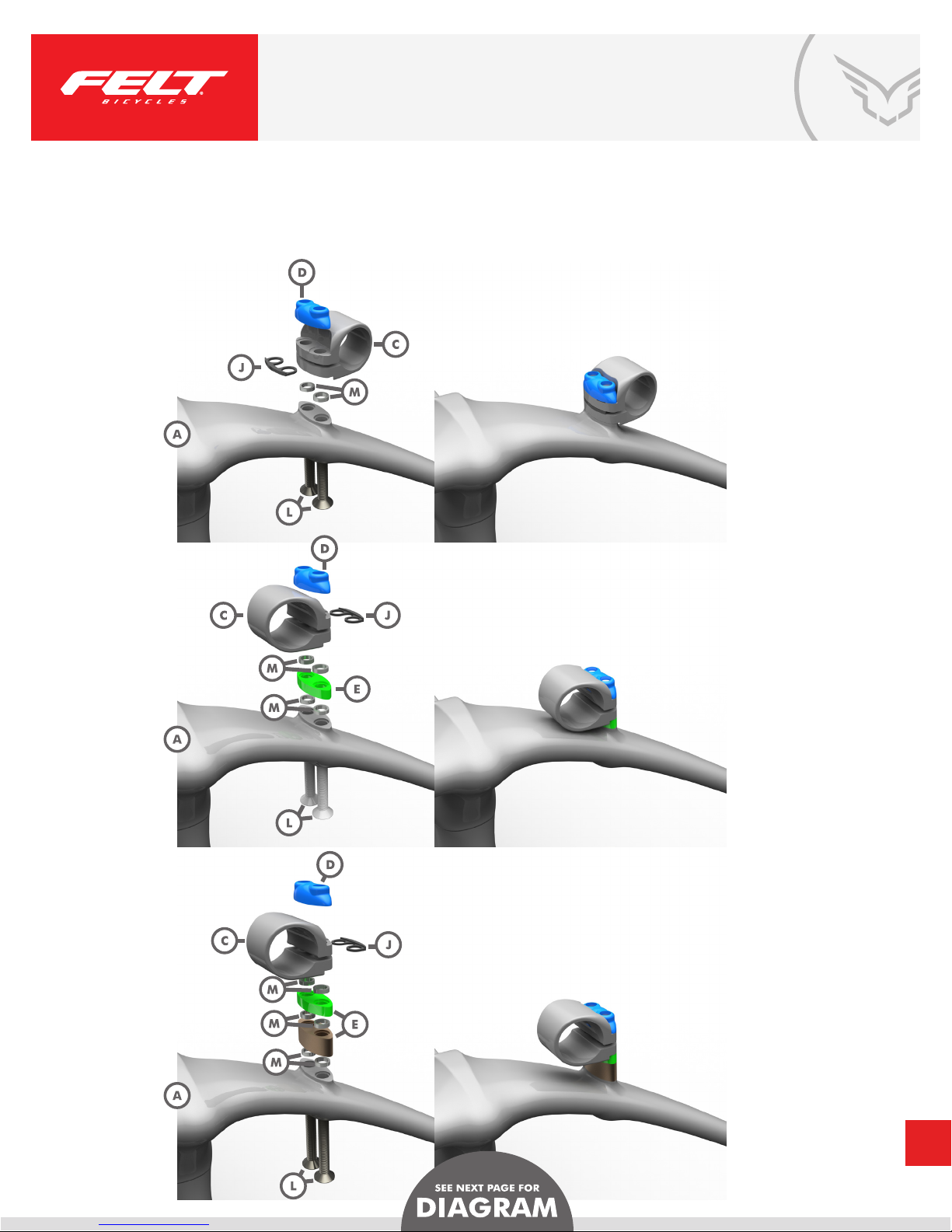
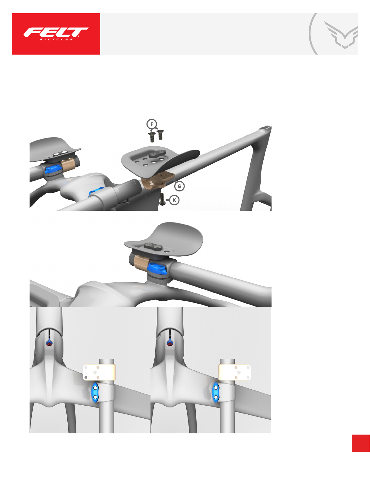
RISER, PAD & EXTENSION INSTALLATION
PARTS:
A. Aerobar
B. 2 x Extensions
C. 2 x Extension brackets
D. 2 x Upper aero nut
E. Aero spacers (5, 10mm)
F. 4 x M5x12mm at head socket cap screw
G. 2 x Arm rest bracket
H. 2 x Arm rests
I. 2 x Arm rest pads
J. Anti-crush washers
K. 2 x M6x15mm socket cap screw
L. 4 x Extension bolts (40, 45, 50, 55mm) 6-8 Nm
M. Fit Washers
STEPS:
The TA FRD armrests can be set up in three distinct congurations—Low, Mid or High—each utilizing
a unique selection of spacers to achieve the rider’s desired position. The Mid conguration can even
be set up in two different heights, depending on the specic spacer used (5mm or 10mm). Refer to the
diagrams on the following page for detailed views of the specic components required.
IMPORTANT: For all congurations, make sure to insert the anti-crush washers
into the extension brackets. Using a torque wrench, tighten bolts to 6-8 Nm.
REQUIRED TOOLS:
- 4mm Allen key
- 5mm Allen key
- Torque wrench
5
Page 6
RISER, PAD & EXTENSION INSTALLATION
40mm
6-8 Nm
45mm
6-8 Nm
55mm
6-8 Nm
6
Page 7
RISER, PAD & EXTENSION INSTALLATION
7
Page 8
SEATPOST INSTALLATION
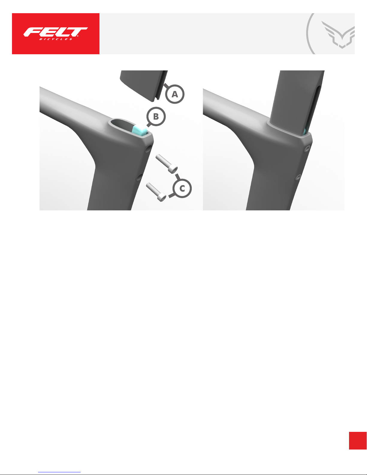
PARTS:
A. Seatpost
B. TA FRD seatpost wedge
C. 2 x M5x18 socket head cap screw
STEPS:
1. Position wedge with taper facing towards the rear of the frame, and the end of the wedge with more material
above the bolt hole to the top.
2. Hold the wedge in place against the frame using your ngers.
3. Insert both M5x18 socket head cap screws through the frame and into the seatpost wedge.
4. Insert seat post into seat tube, sliding wedge into the bottom of the seatpost.
5. Using a 4mm Allen key, repeatedly alternate the tightening of the top and bottom screws to ensure
even pressure. Using a torque wrench, fully tighten both screws to 6 Nm.
REQUIRED TOOLS:
- 4mm Allen key
- Torque wrench
8
Page 9
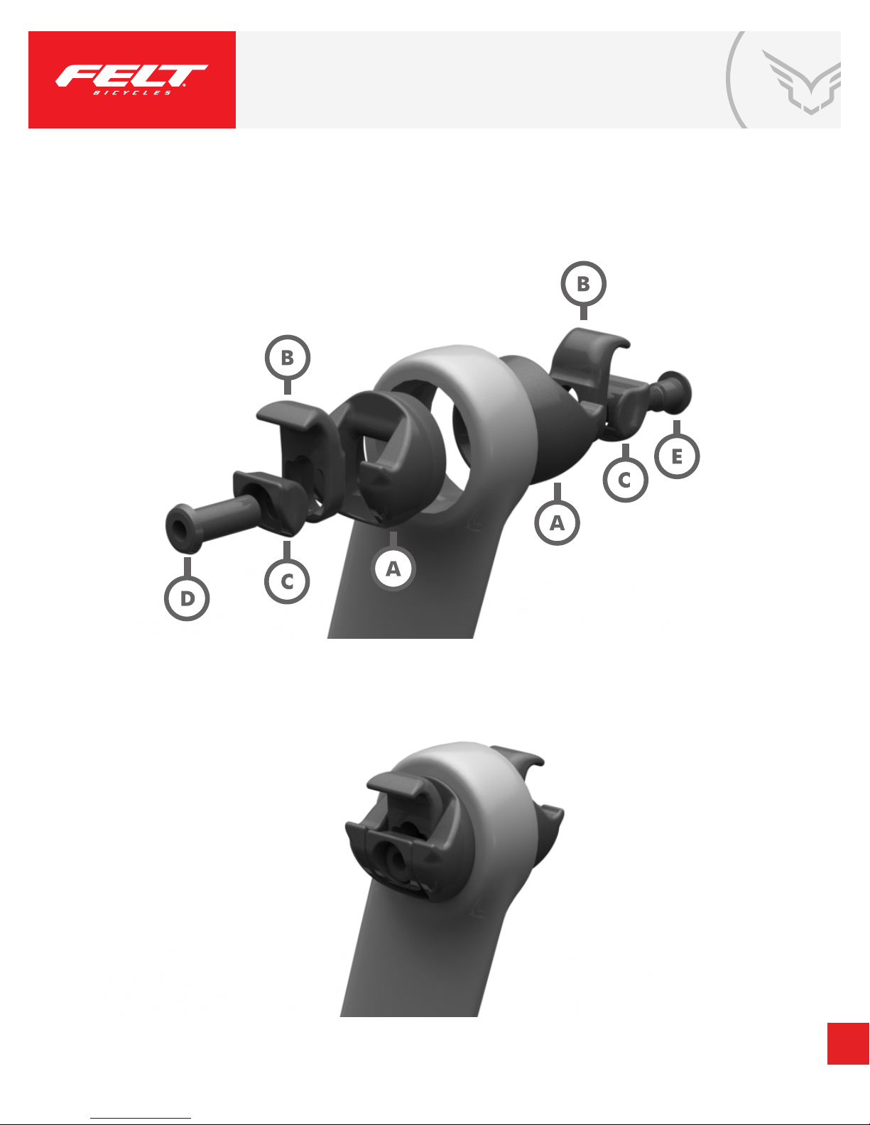
SEATPOST HEAD & SADDLE INSTALLATION:
PARTS:
A. 2 x Saddle Clamp Upper
B. 2 x Saddle Clamp Adjustment Head Half
C. 2 x Saddle Clamp Lower
D. Saddle Clamp Binder Nut
E. Saddle Clamp Binder Bolt
STEPS:
1. Place each Saddle Clamp Upper into a Saddle Clamp Adjustment Head Half, positioning them so the hooked
surfaces are adjacent and can grip a seatpost rail.
2. Place each Saddle Clamp Lower onto a Saddle Clamp Upper, aligning its holes with the oval-shaped holes of
the Saddle Clamp Uppers.
3. Place the bolt and nut threads-down into the holes of the two stacks of Saddle Clamp parts, aligning tooth on
nut to slot in Saddle Clamp Lower.
4. Turn each stack upside down so that the threads face away from your work surface. The chamfer of the
Adjustment Head Half will be placed in contact with the chamfered surface of the seatpost. Apply friction paste
between surfaces.
5. Place one stack thread-side down into the seatpost so the chamfer of the Adjustment Head Half is in contact
with the chamfer of seatpost alloy insert.
6. Holding the remaining stack of pieces in place on the other side of the seatpost, align the bolt threads with the
nut threads and tighten loosely.
7. Slide a saddle (not included) into the saddle clamp assembly beginning from the rear of the saddle.
8. Once your preferred saddle angle and fore/aft position are established, tighten the saddle clamp bolt to 10-12
Nm using a torque wrench.
REQUIRED TOOLS:
- 4mm Allen key
- Torque wrench
- Friction paste
9
Page 10
SEATPOST HEAD & SADDLE INSTALLATION:
10
Page 11
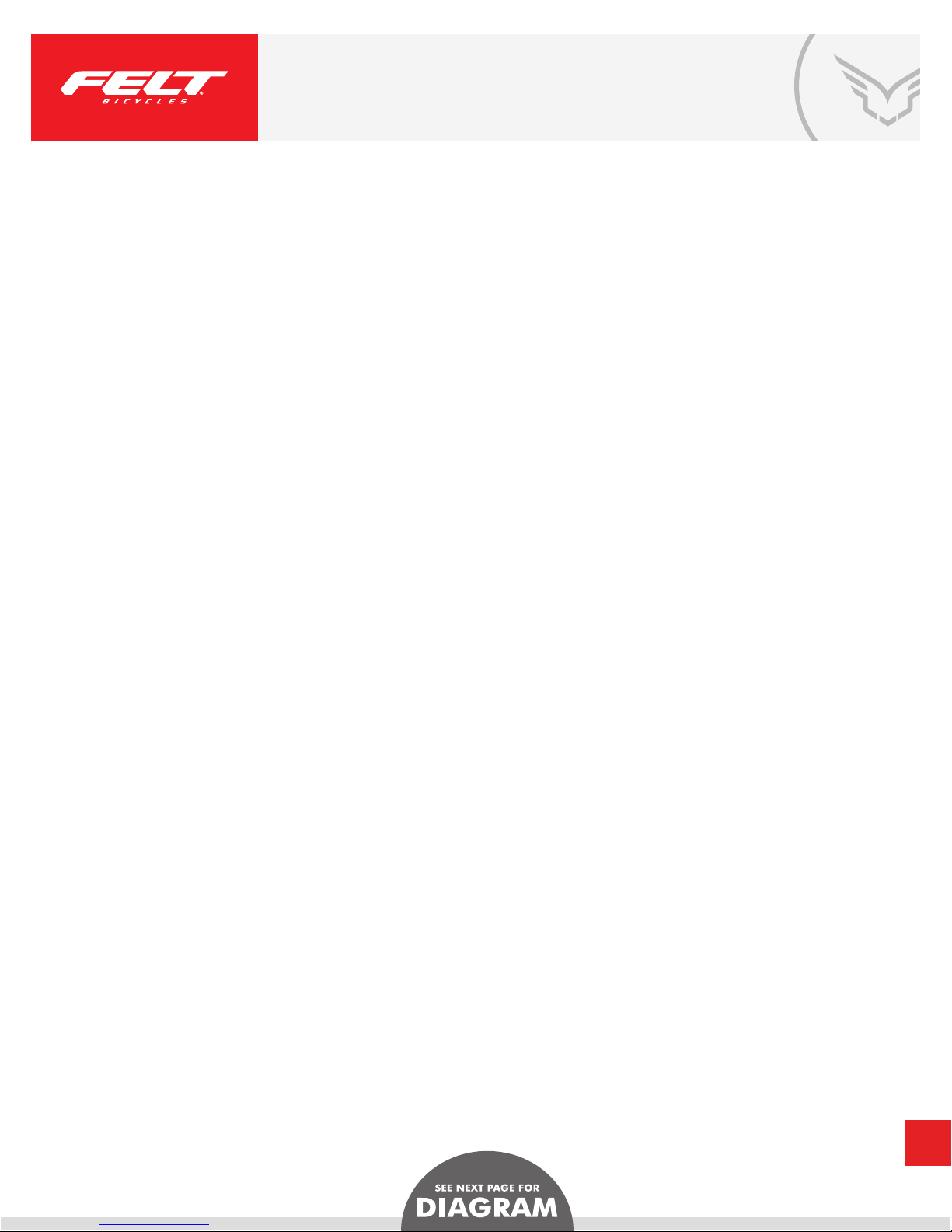
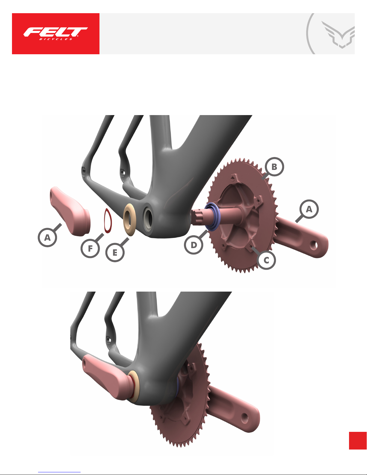
“TRAIN” CRANK INSTALLATION
PARTS:
A. Vision Track Crank, LHD, BB30, 144BCD
B. 50, 51, 52, 53, 54, 55-tooth, 3/32” chain rings
C. 5 x T30 8mm chainring bolts with nuts
D. “Left” 11.7mm aero spacer
E. “Right” 7.7mm aero spacer
F. Wave washer
STEPS:
1. Insert Left 11.7mm aero spacer onto crank spindle.
2. Lightly grease spindle.
3. Insert crank spindle from left to right.
4. Place Right 7.7mm aero spacer onto spindle.
5. Place wave washer onto spindle.
6. Lightly greasy spindle spline.
7. Place right crankarm onto spindle. Tighten with 10mm Allen key and then use
torque wrench to fully tighten to 38-41 Nm.
REQUIRED TOOLS:
- 10mm Allen key
- Torque wrench
- Grease
11
Page 12
“TRAIN” CRANK INSTALLATION
12
Page 13
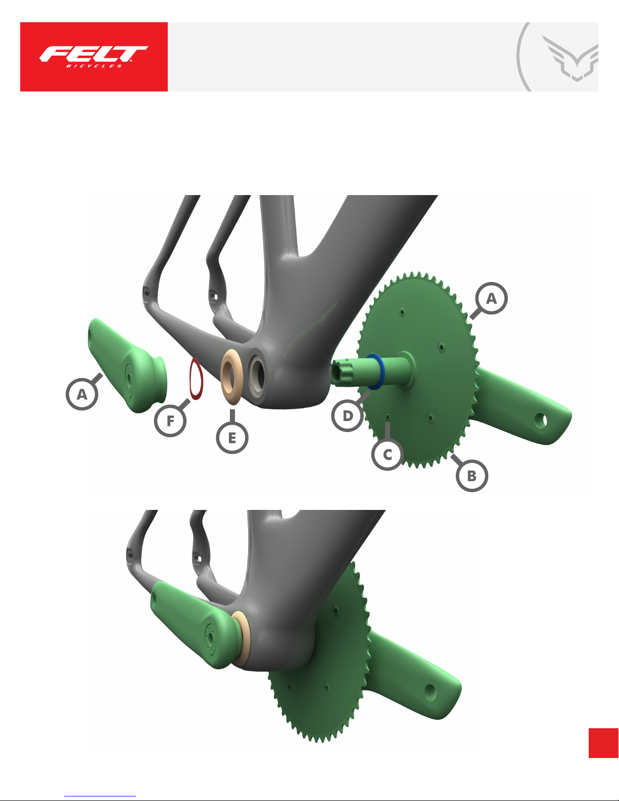
“RACE” CRANK INSTALLATION
PARTS:
A. Vision Metron Aero Crank, LHD, BB30, 130BCD
B. 50, 51, 52, 53, 54, 55T 3/32” chain rings
C. 5x T30 10mm chain ring bolts
D. “Left” 2.0mm aero spacer
E. “Right” 7.7mm aero spacer
F. Wave washer
STEPS:
1. Insert Left 2.0mm aero spacer onto crank spindle.
2. Lightly grease spindle.
3. Insert crank spindle from left to right.
4. Place Right 7.7mm aero spacer onto spindle.
5. Place wave washer onto spindle.
6. Lightly greasy spindle spline.
7. Place right crankarm onto spindle. Tighten with 10mm Allen key
and then use torque wrench to fully tighten to 38-41 Nm.
REQUIRED TOOLS:
- 10mm Allen key
- Torque wrench
- Grease
13
Page 14
“RACE” CRANK INSTALLATION
14
Page 15
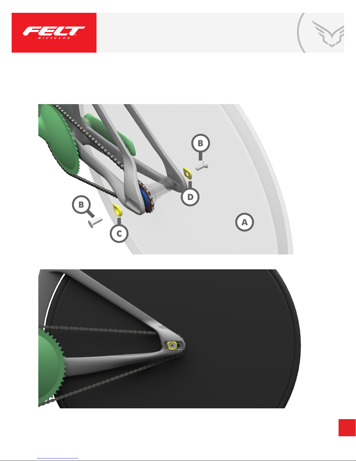
REAR WHEEL INSTALLATION
PARTS:
A. Rear wheel
B. 2 x M8x30 at head socket cap screw
C. 1 x “Left” aero washer for left drop out
D. 1 x “Right” aero washer for right drop out
STEPS:
1. Insert rear wheel into 95mm rear drop out.
2. Place both aero washers onto M8x30 at head socket cap screws. Note: the tops of the
screws should t ush with outside surface of washer.
3. Align front of washer to drop out. These surfaces should be parallel to one another.
4. Thread screws into hubs. Tighten loosely with 5mm Allen key, then fully tighten
to 20-22 Nm with torque wrench.
REQUIRED TOOLS:
- 5mm Allen key
- Torque wrench
15
Page 16
REAR WHEEL INSTALLATION
16
Page 17
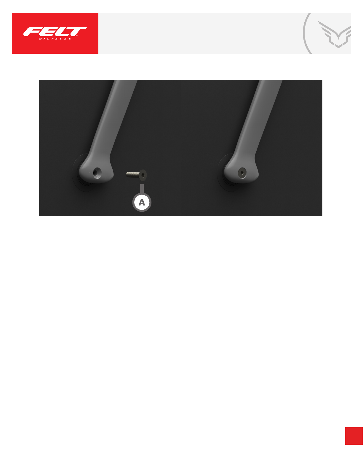
FRONT WHEEL INSTALLATION
PARTS:
A. 2 x M6x20 at head socket cap screw
STEPS:
1. Insert front wheel into 70mm front drop out.
2. Thread M6x20 at head socket cap screws into hubs. Tighten loosely with
4mm Allen key, then fully tighten to 6-8 Nm with torque wrench.
REQUIRED TOOLS:
- 4mm Allen key
- Torque wrench
17
Page 18
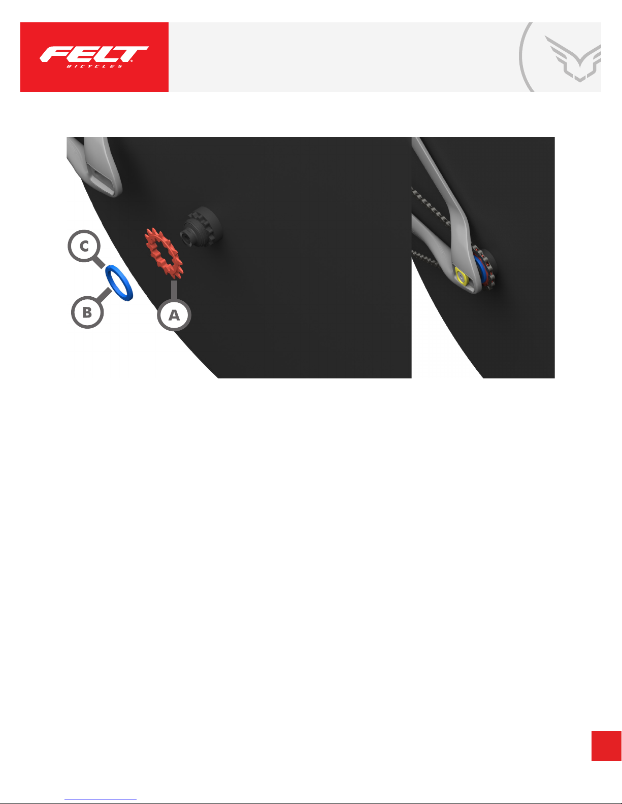
COG & LOCKRING INSTALLATION
PARTS:
A. Phil Wood 13, 14, 15, 16-tooth, 3/32”, spline drive cogs
B. Phil Wood, black, “FELT TEAM USA” 1.32x24 TPI,
left-handed thread for “Train” wheels with black
Phil Wood hubs
C. Phil Wood or White Industries, silver, 1.29x24 TPI,
left-handed thread for “Race” disc wheels with silver hubs
STEPS:
1. Align cog splines with hub and press until fully seated.
2. Left-hand thread appropriate lockring. Then use lockring wrench to tighten.
REQUIRED TOOLS:
- Lockring Wrench
18
 Loading...