

Page 1
REDEMPTION
SUSPENSION
MANUAL
Page 2
REDEMPTION
Congratulations on acquiring a Felt Redemption!
As with all of our high-performance bikes and
components, our aim is to provide you, the rider, with
the absolute best riding experience. Like all bicycles
with performance-oriented suspension, the Redemption
will require occasional maintenance. Be sure to read
this manual thoroughly, as it will help you set up
your bike correctly. If you have any questions about
maintenance or setting up your bike properly, we
strongly recommend consulting with your authorized
Felt retailer.
For more information, visit: FELTBICYCLES.COM
16
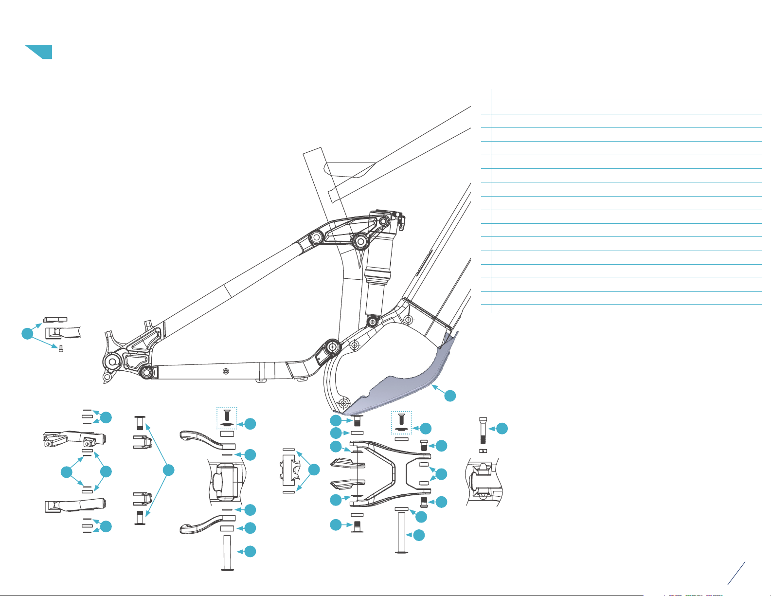
SUSPENSION HARDWARE:
1 Lower shock mounting bolt (36.7mm length and collet) 1
2 Main pivot hardware (75.5mm shaft, 16mm bolt and cap) 1
3 Main pivot bearign spacer (2mm thick) 2
4 Main pivot bearing (3902) 2
5 Rocker pivot hadware (72mm length shaft, 16mm length bolt and cap) 1
6 Rocker pivot spacers (3.3mm) 2
7 Rocker pivot bearings (6902) 2
8 Trunnion mount bolts (1.5mm length) 2
9 Trunnion mount bearings (DRF 1017 2RS) 2
10 Seatstay pivot hardware (18mm length) 2
11 Seatstay pivot spacers (3mm thick) 2
12 Seatstay pivot bearings (6900) 2
13 Chainstay pivot harware (22.5mm length) 2
14 Chainstay pivot spacers (1mm thick) 6
15 Chainstay pivot bearings ( 6800) 4
16 Derailleur hanger and bolt 1
17 Motor cover
14
14
15
14
13
17
2
3
3
4
2
10
12
11
6
11
10
5
8
9
8
7
5
1
3
Page 3
REDEMPTION
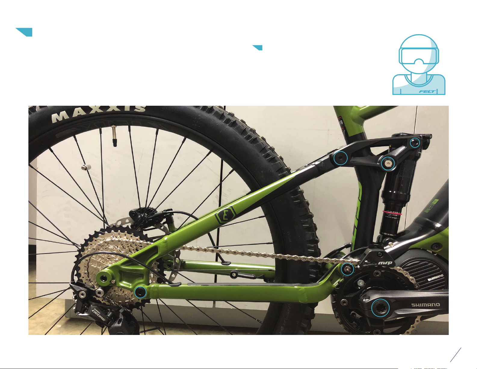
The suspension on your Redemption is a meticulously engineered system
designed for high-performance off-road riding. As such, we strongly
recommend that all mechanical work and maintenance be performed by an
authorized Felt retailer. Should you decide to perform the work yourself,
be sure to read the complete manual in order to fully understand the
process and its various requirements.
SAFETY FIRST
We care about you. Please, always
wear your safety glasses and protec tive
gloves when servicing Felt products.
Protect yourself ! Wear your safety gear!
5
Page 4
REDEMPTION
Before you begin work on your Redemption's suspension, be sure to clean
the bike thoroughly, paying extra attention to remove any and all dirt,
grease, and grime from the suspension components using non-abrasive
cleaning agents. Once you are sure that the bike is clean and free of
contaminants, complete the following steps to service your Redemption's
suspension.
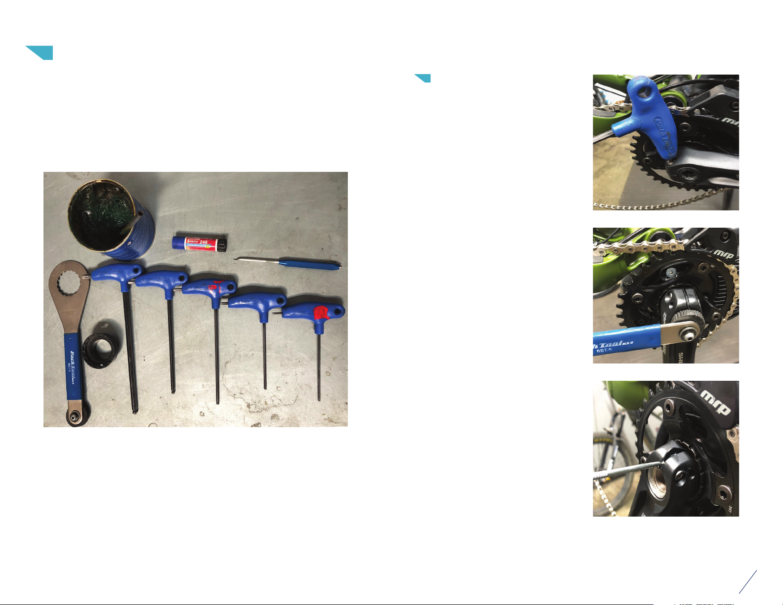
STEP 1
Using 5mm Allen, loosen the pinch
bolts holding the drive side crank
arm on.
Use BBT-9 tool to remove crank
arm pre-load screw.
Required Tools:
— Park Tools BBT-9
— Shimano tool TL-FC 39 (to remove chain ring)
— Allen wrenches 8mm, 6mm, 5mm, 4mm, 3mm
— Small pick
— Grease
— Blue Loctite
Use pick to release crank arm
safety clip.
01
Page 5
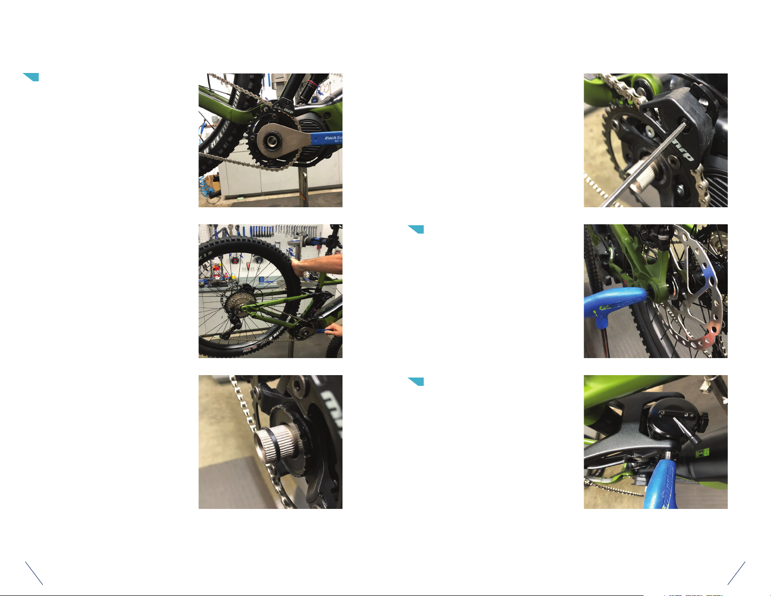
STEP 2
Use Shimano TL-FC 39 tool and
BBT-9 to remove chain ring.
Loosen chain guide and remove
chain ring.
Hold rear wheel and turn wrench
clockwise to remove.
Note small spacer on spindle. Keep
with chain ring lock ring so as not
to lose it.
STEP 3
Remove rear wheel using 6mm
Allen.
STEP 4 UPPER LINK REMOVAL
Start by removing the trunnion bolts
using a 6mm Allen and rock the
shock forward and out of the way.
0302
Page 6
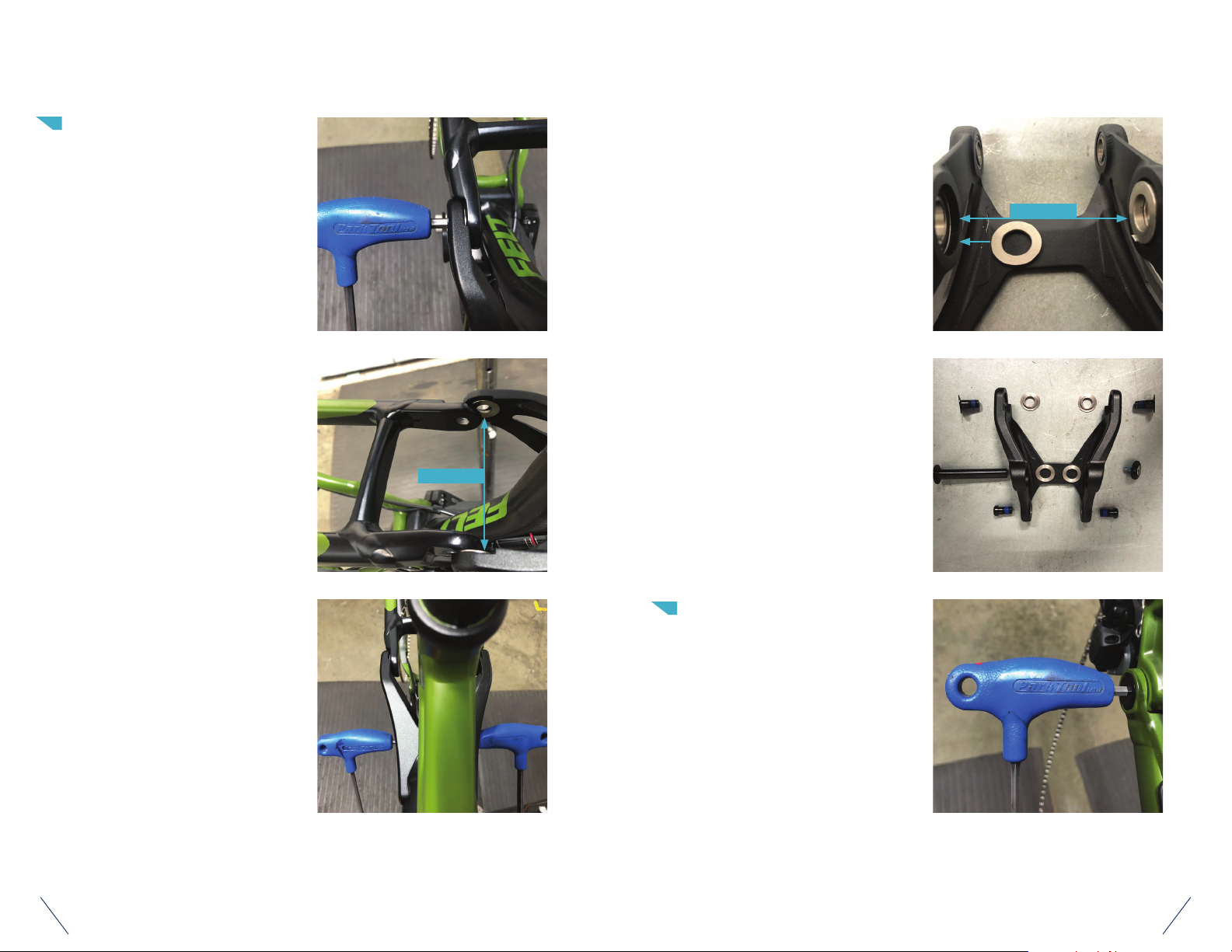
STEP 4 UPPER LINK REMOVAL CONT.
Remove seat stay pivots using 5mm
Allen.
Note spacers between link and
frame.
SPACERS
Note spacers between link and seat
stay.
Remove main link pivot using 6mm
and 4mm Allens.
Link and hardware.
SPACERS
STEP 5
Remove chain stay pivots using
5mm Allen (note two spacers, one
on each side of bearing).
0504
Page 7
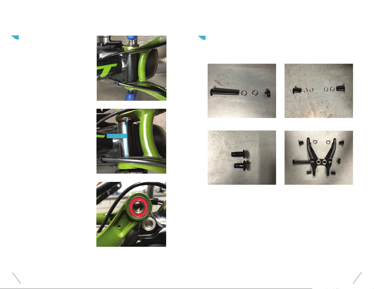
STEP 6
Using 8mm and 4mm Allens,
remove the main pivot.
Note spacers between swing arm
and frame.
SPACERS
STEP 7
Clean and inspect all bearings and hardware, check for roughness and excessive
wear. Replace bearings as needed. Follow steps in reverse for assembly.
MAIN PIVOT
CHAINSTAY PIVOT
Check main pivot bearings to make
sure they are still smooth in their
rotation.
22.5 MM chains tay pivot b olt and
18mm se at sTAY pivo t bolt
*Special note*
The seat stay bolt and chain stay bolt are similar looking. If you get these
mixed up, the longer bolt (22.5mm) goes in the chain stay and the shorter
18mm bolt goes into the seat stay to the link.
rock er link (se at stay pivo t, rocker lin k
main pivot and tunnion mount)
0706
Page 8
STEP 8
Torque bolts to following specifications
— Seat stay - 10NM
— Chain stay - 10NM
— Main pivot - 14NM
— Link pivot - 12NM
— Trunnion bolts - 10NM
— Follow Shimano specifications for chain
ring and crank arm
STEP 9
Congratulations! You are now ready to continue hours
of enjoyment aboard your Felt Redemption.
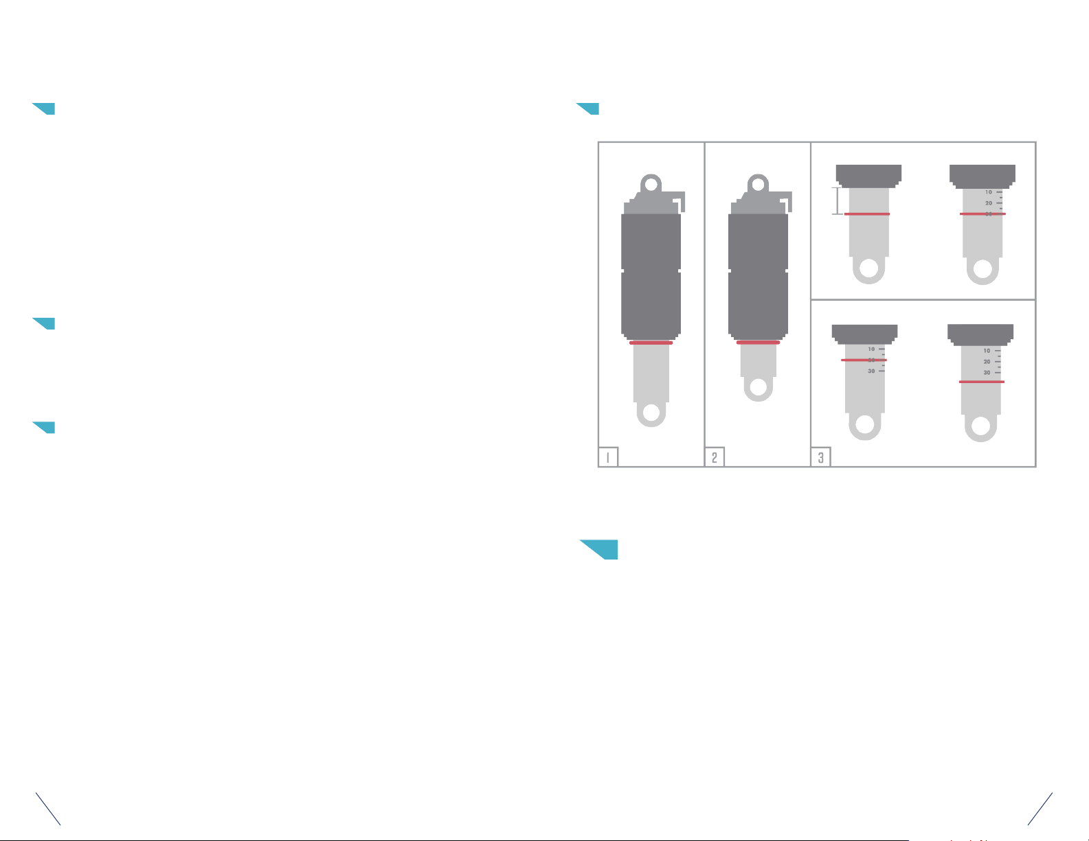
SHOCK SETUP
1. Push the o-ring to the top of the shock shaft.
2. Sit on the bike with the seat at full ride height to compress the shock. Bounce
a few times, then push the o-ring back to the top of the shaft.
3. Gently get off the bike, taking care not to change the position of the o-ring.
On some shock models, the sag gradients will be printed on the shaft. In this
case, simply read your sag percentage as it is printed on the shock shaft. If
there are no sag gradients, measure the distance of the o-ring from the top of
the shaft. To achieve 30% sag, the o-ring should be 20mm from the top of the
shaft. If there is too much sag (>30%) add air pressure, if there is not enough
sag (<30%), reduce air pressure.
4. Repeat process until desired sag is achieved.
SHOCK SETUP
CONTACT
Felt BICYCLES
30452 ESPERANZA
RANCHO SANTA MARGARITA, CA 92618
USA
INFORMATION
CORRECT
20MM
OR
NOT CORRECT
+ PRESSURE- PRESSURE
Time Sport International SAS
725 rue Aristide Berges- Bâtiment Reflex
38340 Voreppe, France
FELTBICYCLES.COM
0908
Page 9
 Loading...