

Felt DECREE 1.5 Technical Manual

DECREE 1.5
TECHNICAL
MANUAL

DECREE 1.5
Congratulations on purchasing a Felt Decree 1.5. As with all of
our bikes and components, our aim is to provide the rider with the
best product and riding experience. Read this manual supplement
thoroughly, as it’s to help you set your bike up correctly,
and care for it.
For further information, visit:
FELTBICYCLES.COM
INTRODUCTION

1
CONTENTS
INTRODUCTION
Fast Explained ..........................................................................................................................2-3
Geometry
.....................................................................................................................................4
SETUP
Shock Setup .................................................................................................................................5
Flip Chips .....................................................................................................................................6
Headtube Cable Guides ...............................................................................................................6
Bottom Bracket Cable Guides ......................................................................................................7
CABLE ROUTING
Rear Brake Cable/Hose Routing ............................................................................................... 8-9
Rear Shifter Cable/Hose Routing...........................................................................................10 -11
Dropper Post Cable/Hose Routing.........................................................................................12-13
MAINTENANCE
Evaluation ..................................................................................................................................14
Pivot Location / Torque Values
...................................................................................................15
Main Pivot
.............................................................................................................................16-17
Seat Tube Pivot
..................................................................................................................... 18-19
Seat Stay Pivot
......................................................................................................................20-21
Shock Mount Pivot
................................................................................................................ 22-23
REPLACEMENT PARTS
Master Parts List .........................................................................................................................24
CONTACT INFORMATION
Contact ......................................................................................................................................25
2
FAST EXPLAINED
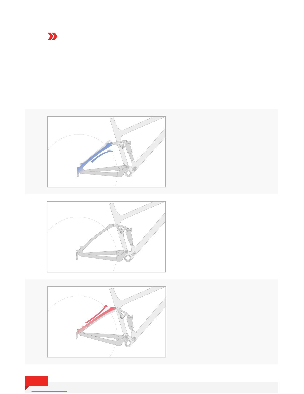
FAST, or Felt Active Stay Technology, is a linkage-driven, single pivot
system with exible carbon stays. By replacing the pivot near the dropout
with exible carbon stays a lighter, stiffer, and overall snappier frame
can be made.
COMPRESSED
0% Travel (Top-Out): In order for
the suspension to reach full extension,
the rear triangle is required to
compress.
EXTENDED
100% (Bottom-Out): As the
suspension gets deeper in the
travel, the rear triangle is required
to extend.
NEUTRAL
30% Travel (Sag): At the sag
point (approximately 30%), the
rear triangle is neutral.
3
FAST EXPLAINED
CONT.
Efcient Pedaling: In order to provide efficient pedaling, FAST relies on both ideal
anti-squat values as well as the flexible carbon stays. As the suspension moves away from
the sag point in either direction, a force is created from either compressing or extending the
stays. This force acts on the shock and helps return it back to sag. This provides a stable,
responsive platform for pedaling.
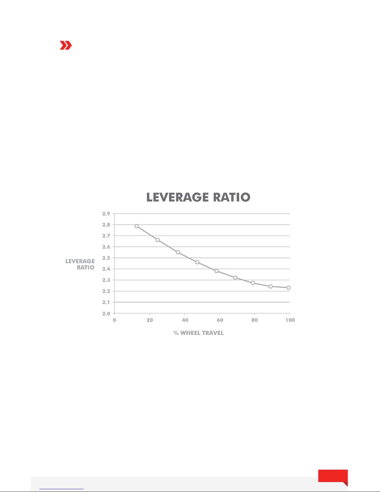
Large Impacts: Support for large impacts is provided in two ways: decreasing leverage
ratio and carbon flex. The leverage ratio is decreasing which makes it progressively harder
to compress the suspension as it moves through the travel. The carbon stays add to this by
contributing an additional spring force as they are extended through the travel.
Small-Bump Sensitivity: With the pedaling performance and large impact support
handled by the linkage design and flexible carbon stays, the shock can be run with
minimal compression damping. This frees the shock up to remain active and absorb
the smallest of bumps.

4
GEOMETRY
*Geometry chart reects low/slack ip chip position
A
B
C
D
E
F
G
H
I
J
K
L
M
N
S (16”)
67
73.2
565
90
395
12
428
676
1104
529
42
12
391
576
M (18”)
67
73.2
595
105
430
12
428
708
1136
529
42
12
417
590
L (20”)
67
73.2
625
125
485
12
428
740
1168
529
42
12
441
609
XL (22”)
67
73.2
655
145
540
12
428
772
1200
529
42
12
465
627
Size
Head Tube Angle
Seat Tube Angle
Top Tube Horizontal
Head Tube
Seat Tube
BB Drop
Chainstay
Front Center
Wheelbase
Fork Length
Rake
Lower HS Stack
Reach
Stack
5
SHOCK SETUP
It is very important to have the correct amount of sag so that the suspension can be in the
part of its travel that is most efficient and compliant. Felt recommends starting at 30% and
adding/subtracting up to 5-10% to fine tune to your personal preference.
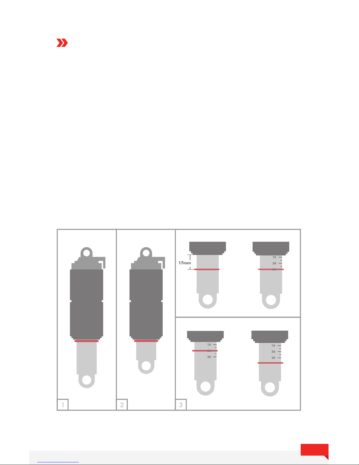
To measure sag, follow these 4 steps:
1. Push the o-ring to the top of the shock shaft.
2. Sit on the bike with the seat at full ride height to compress the shock. Bounce a few times, then push the
o-ring back to the top of the shaft.
3. Gently get off the bike, taking care not to change the position of the o-ring. On some shock models, the
sag gradients will be printed on the shaft. In this case, simply read your sag percentage as it is printed on the
shock shaft. If there are no sag gradients, measure the distance of the o-ring from the top of the shaft. To
achieve 30% sag, the o-ring should be 17mm from the top of the shaft. If there is too much sag (>30%)
add air pressure, if there is not enough sag (<30%), reduce air pressure.
4. Repeat process until desired sag is achieved.
CORRECT
NOT CORRECT
OR
+ PRESSURE- PRESSURE
6
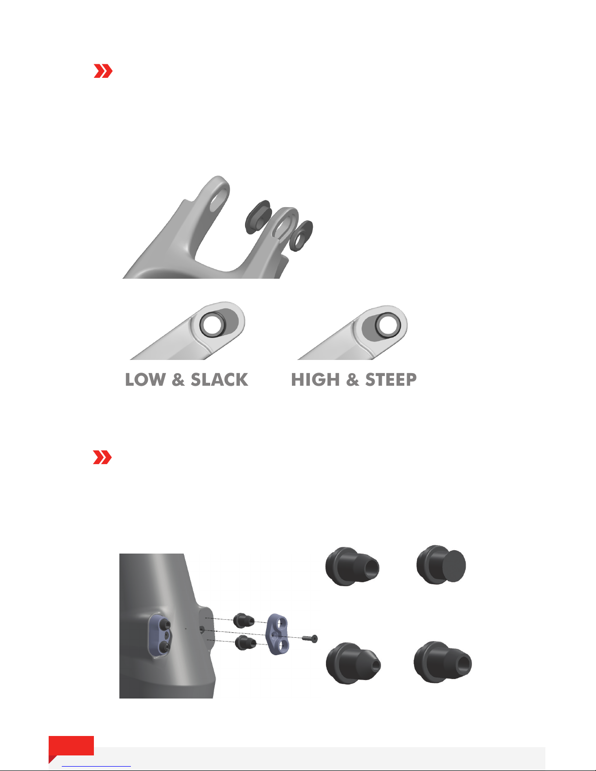
FLIP CHIPS
The geometry can be adjusted by rotating eccentric chips located in the
seat stay pivot. By changing the orientation of these chips, the bottom
bracket height will be raised or lowered by 10mm and the head angle
will be slackened or steepened by 1 degree.
HIGH & STEEP
LOW & SLACK
BOTTOM BRACKET
+/- 10MM
HEAD ANGLE
+/- 1 DEG.
HEAD TUBE CABLE GUIDES
The head tube cable guides contain rubber reducers for all cable sizes
that are interchangeable and can be arranged to fit each rider's setup
and personal preferences.
Di2 (2mm) Shift (4mm)
Brake (5mm) Blank Plug
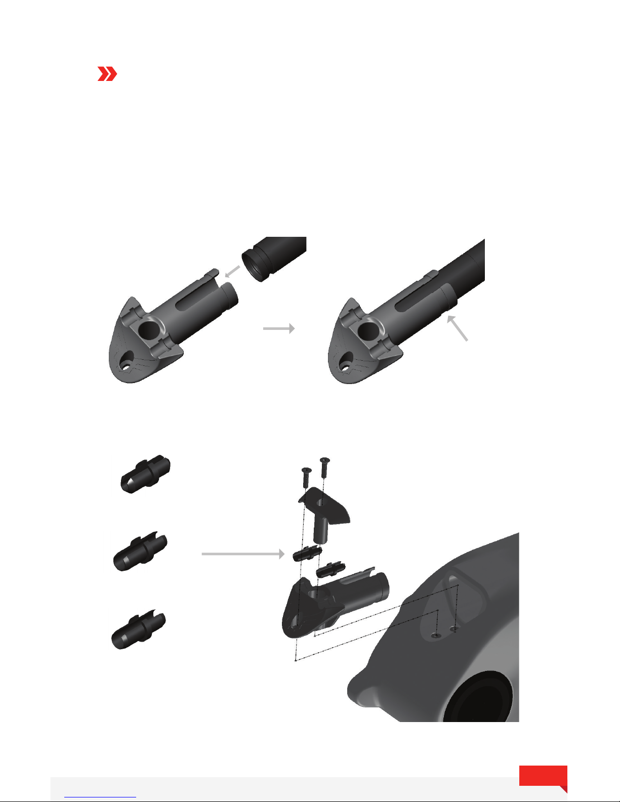
7
BOTTOM BRACKET
CABLE GUIDES
The bottom bracket cable guide can be adapted to different
configurations with rubber reducers for different sizes of cables.
It can also be used as a battery holder.
Wrap zip tie around
to hold battery
in place.
Di2 (2mm)
Shift (4mm)
Brake (5mm)
 Loading...