

Felt AR Owner's Manual

AR Owner’s Manual

Felt AR InternaLoc Seatpost Assembly
and Cable Routing Manual
This manual is not intended as a comprehensive use,
service, repair or maintenance manual. Please see your
dealer for all service, repairs or maintenance. Your dealer
may also be able to refer you to classes, clinics or books
on bicycle use, service, repair or maintenance.
Note:
Part IV AR Mechanical Compatible Frame
Mechanical Routing Instruction
Electronic Wiring Instruction
Part V AR Electronic Specific Frame
Electronic Wiring Instruction
Part VI Brake Routing Instruction
Pg. 25-34
Pg. 35-45
Pg. 46-54
Pg. 55-56
. . . .
. . . . . .
. . . . . .
. . . . . . .
Part I VM Seat Clamp
Part II VR Seat Clamp
Part III InternaLoc Seatpost
Pg. 1-5
Pg. 6-8
Pg. 9-22
. . . . . . . . . . . .
. . . . . . . . . . . . .
. . . . . . . . . .
1. Saddle Clamp Upper (x2)
2. Saddle Clamp Adjustment Head Half (x2)
3. Saddle Clamp Lower Clamp (x2)
4. Saddle Clamp Binder Nut with Keyway
5. Saddle Clamp Binder Bolt
6. VM Seatpost
AR Seatpost & Small Parts
VM Saddle Clamp Assembly
1 4
253 6
-1-
Locate the two AR saddle clamp
Lowers and place each onto a
saddle clamp Upper, aligning
the holes with the oval-shaped
holes of the saddle clamp
Uppers as illustrated below.
Step 2
The parts should appear as the
image on the left, in two stacks
of three pieces, with the bolt,
nut and seatpost remaining.
Step 3
Locate the two AR saddle clamp
Uppers and place each into a
saddle clamp adjustment Head
Half, positioning them so the
hooked surfaces are adjacent
and can grip a seatpost rail.
Step 1
-2-

The chamfer of the adjustment
head half will be placed in
contact with the chamfered
surface of the seatpost. Apply
friction paste between surfaces.
Being cautious to maintain
the order of parts in each
stack, turn each stack
upside down on the table
so now the threads face
away from the table.
Place the bolt and nut threadsdown into the holes of the two
stacks of pieces as pictured,
aligning tooth on nut to slot in
saddle lower clamp.
Step 5
Step 4
Note: Grease bolt threads.
-3-

Pick up one stack and place it thread-side down into the
seatpost so the chamfer of the adjustment head half is in
contact with the chamfer of seatpost alloy insert as pictured.
Holding the remaining stack of pieces in place on the other
side of the seatpost, align the bolt threads with the nut threads
and tighten 2 to 3 turns.
Step 7
Step 6
-4-

Once saddle angle and fore/aft position
are adjusted, tighten the saddle clamp
bolt to 10-12 nm of torque.
Slide the saddle into the saddle clamp
assembly beginning from the rear of the
saddle.
Step 9
Step 8
-5-

VR Saddle Clamp Assembly
1. VR Seatpost
2. 3T Saddle Clamp Inner Splined Adjusment Cylinder
3. 3T Saddle Clamp Outer Splined Adjustment Cyclinder
4. 3T Saddle Clamp Outer Clamp
5. 3T Saddle Clamp Binder Bolt
VR Seatpost & Small Parts
1 4
253
-6-

Slide the Inner Splined Adjustment
Cylinder into the Outer Splined
Cylinder as pictured.
Slide the Inner and Outer Splined
Adjustment Cylinder assembly into
the VR seatpost as pictured.
Place the Outer Clamp piecs over either end of the
Inner and Outer Adjustment Cylinder assembly and
insert binder bolts through the hole on the face of
the Outer Clamp pieces as pictured. Align threads
on binder bolts with the threads on Inner Splined
Adjustment Cylinder.
Step 2
Step 3
Step 1
Note: The 3T Outer Clamp
parts supplied are for 7mm
round rails. Optimal Outer
Clamp pieces are available
for other saddle rail options
from 3T.
-7-

Install the AR/3T saddle clamp
Outer Clamp and Binder Bolt
assembly, one on each side ot the
VR seatpost, and adjust the saddle
fore/aft position and angle. Tighten
the Binder Bolt to 5 nm.
Slide the saddle rails onto the
clamp assembly starting at the back
of the saddle.
Step 5
Step 4
-8-

The Felt AR can carry the battery
to power Shimano Di2 inside the
aerodynamic seatpost using a
mounting clip supplied with the
seatpost.
Felt AR:
Seatpost Assembly
-9-
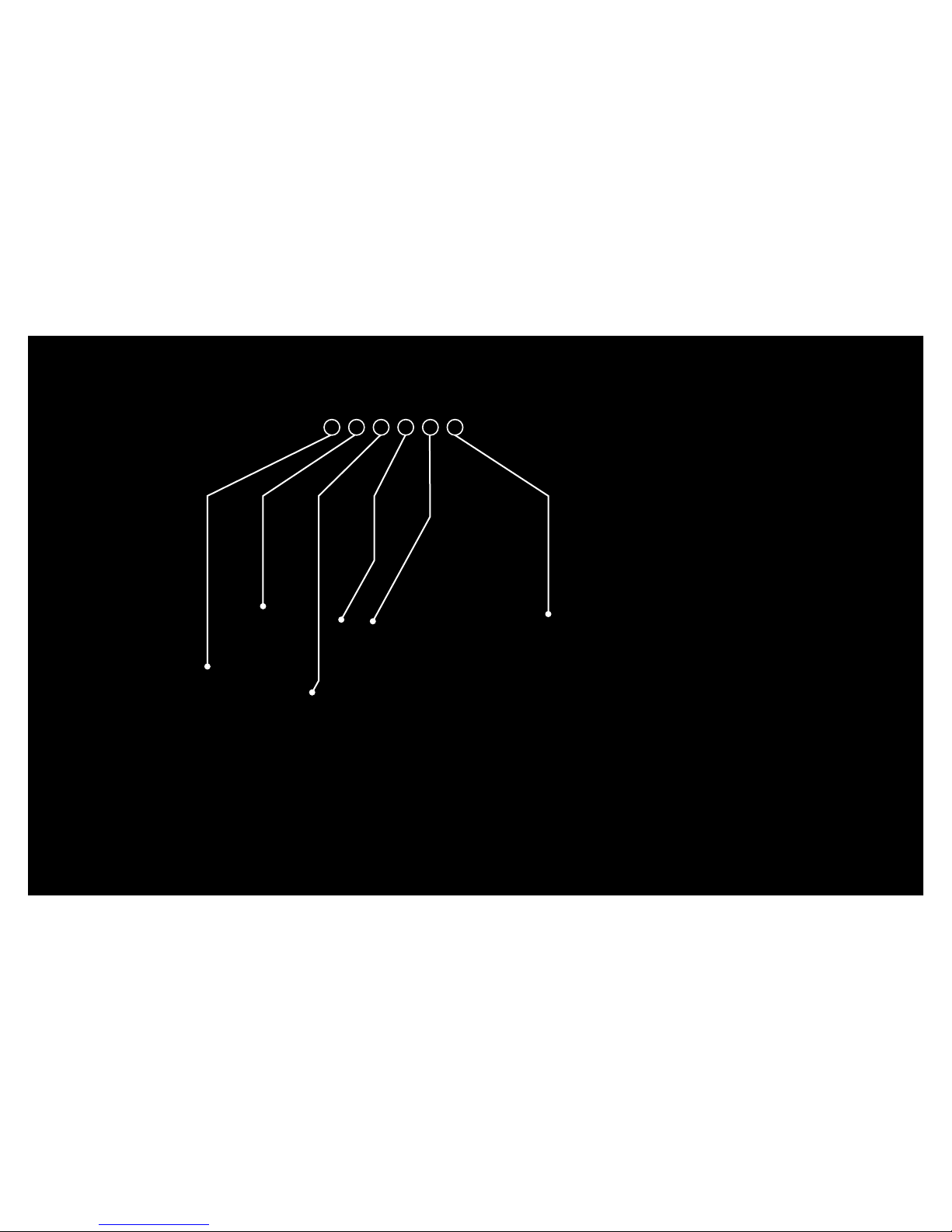
1. AR Seatpost
2. Shimano Di2 Battery Clip
3. Seatpost Binder Bolts
4. Compression Spring
AR Seatpost Parts
5. Seatpost Slot
6. InternaLoc Seatpost Wedge
7. Seatpost Seals
InternaLoc Seatpost Assembly
1 4
253 6
7
-10-

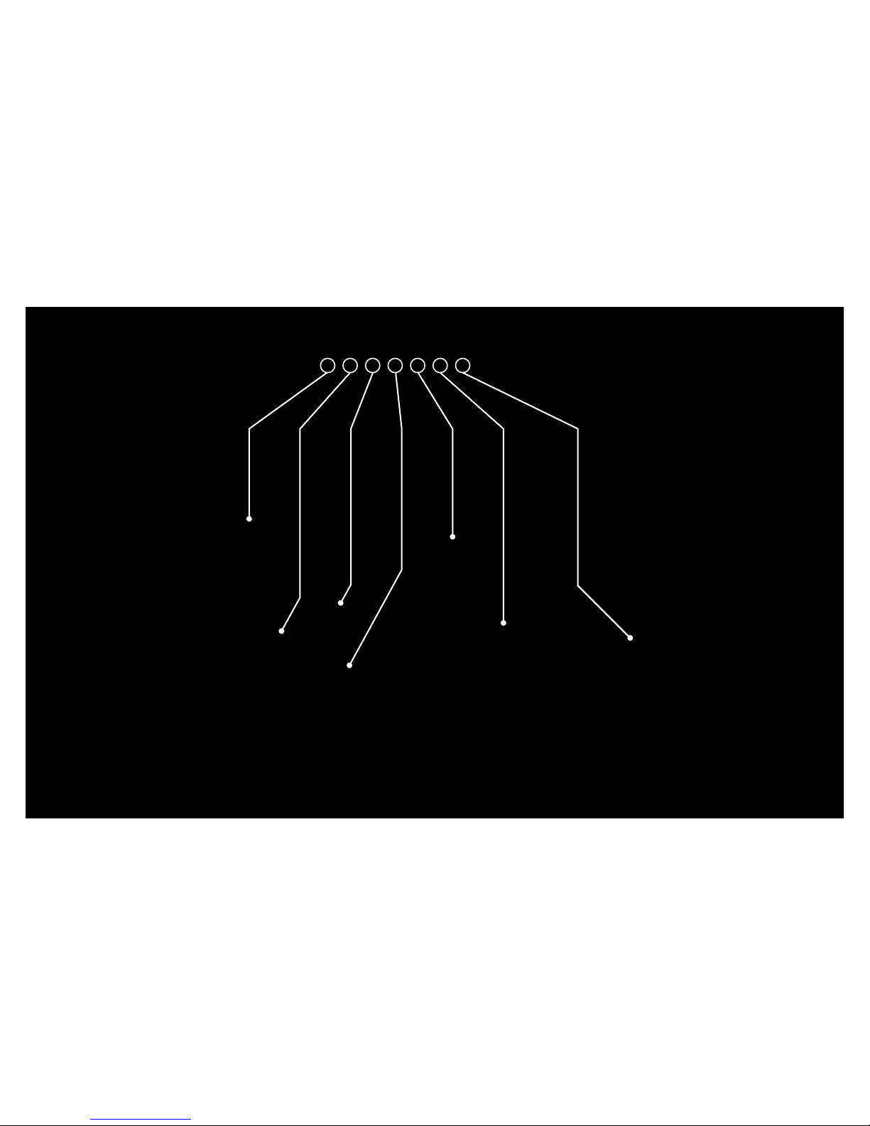
The Shimano Di2 Battery Clip and Compression Spring mount
between the two halves of the black InternaLoc Seatpost Wedge.
This Shimano Di2 Battery Clip hangs inside the InternaLoc Seatpost
Wedge assembly.
Step 1
-11-

To install the Shimano Di2 Battery Clip and Compression Spring into the InternaLoc Seatpost Wedge, place one half of
the InternaLoc Seatpost Wedge on a flat surface. Place one of the round mounting pins at the top of the Shimano Di2
Battery Clip into the small indent toward the bottom edge of the first half of the black InternaLoc Seatpost Wedge. Place
the Compression Spring into the larger indent at the center of the InternaLoc Seatpost Wedge. Place the other half of the
InternaLoc Seatpost Wedge on top of the bottom half seating spring and Shimano Di2 Battery Clip mounting pin in the
appropriate indentations.
-12-

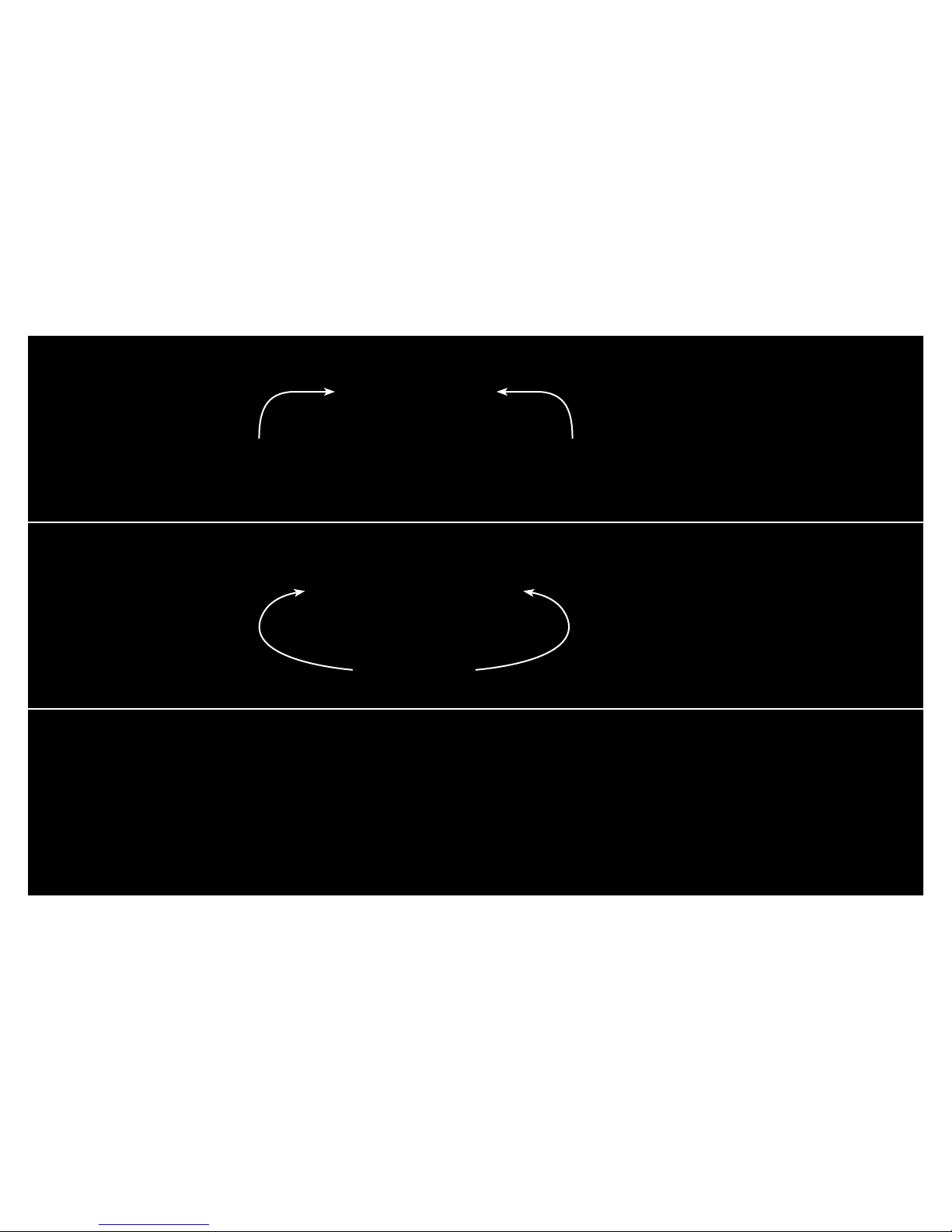
After the Shimano Di2 Battery Clip and
Compression Spring are installed in the two halves
of the InternaLoc Seatpost Wedge, orient the
seatpost and battery mount assembly so the bottom
edge will slant downward toward the ground at the
front of the bike. The leading edge of the assembly
will extend downward to be the lowest point when
hanging from the seatpost.
Step 2
-13-
Squeeze the assembly together with the front being
the lowest point (angled downward toward the
front of the bike) and insert it into the bottom of the
seatpost.
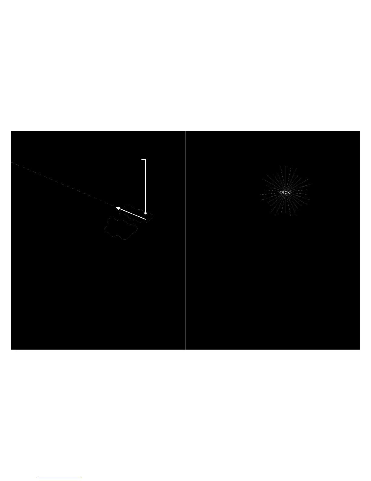
Note: Apply a thin coat of carbon friction paste
on the surface of aluminum InternaLoc Seatpost
Wedge that will contact the carbon fiber surface
of seatpost to prevent slipping or noise.
Slide the assembly up into the seatpost until the
guides on each side of the internal seatpost wedge
snap into the slots on each side of the seatpost.
Be sure to keep the assembly at the bottom of the
seatpost for now.
click!
click!
-14-

The Shimano Di2 SM-BTR2 cylinder shaped battery
installs in the bottom of the clip that you installed
between the two halves of the InternaLoc Seatpost
Wedge in Step 2. To install the battery, first slide a soft
“O” ring over the Shimano SM-BTR2 battery.
Step 3
-15-

Before moving on to Step 4, installing the seatpost
assembly into the AR bike frame, be sure to attach the
Shimano Di2 wire to the battery so the derailleurs can be
powered by the Shimano Di2 SM-BTR2 cylinder-shaped
battery.
With the battery cable connector facing downward,
push the battery into the claw-shaped clip until the
brackets on the clip snap into place on the battery.
-16-
 Loading...