

Page 1

Brisa
™
assembly and operation instructions
electric table base
model 2B-C48-__-___
__ = color combination (shroud/feet)
___ = SLV, BLK or WHT (column and frame)
Page 2
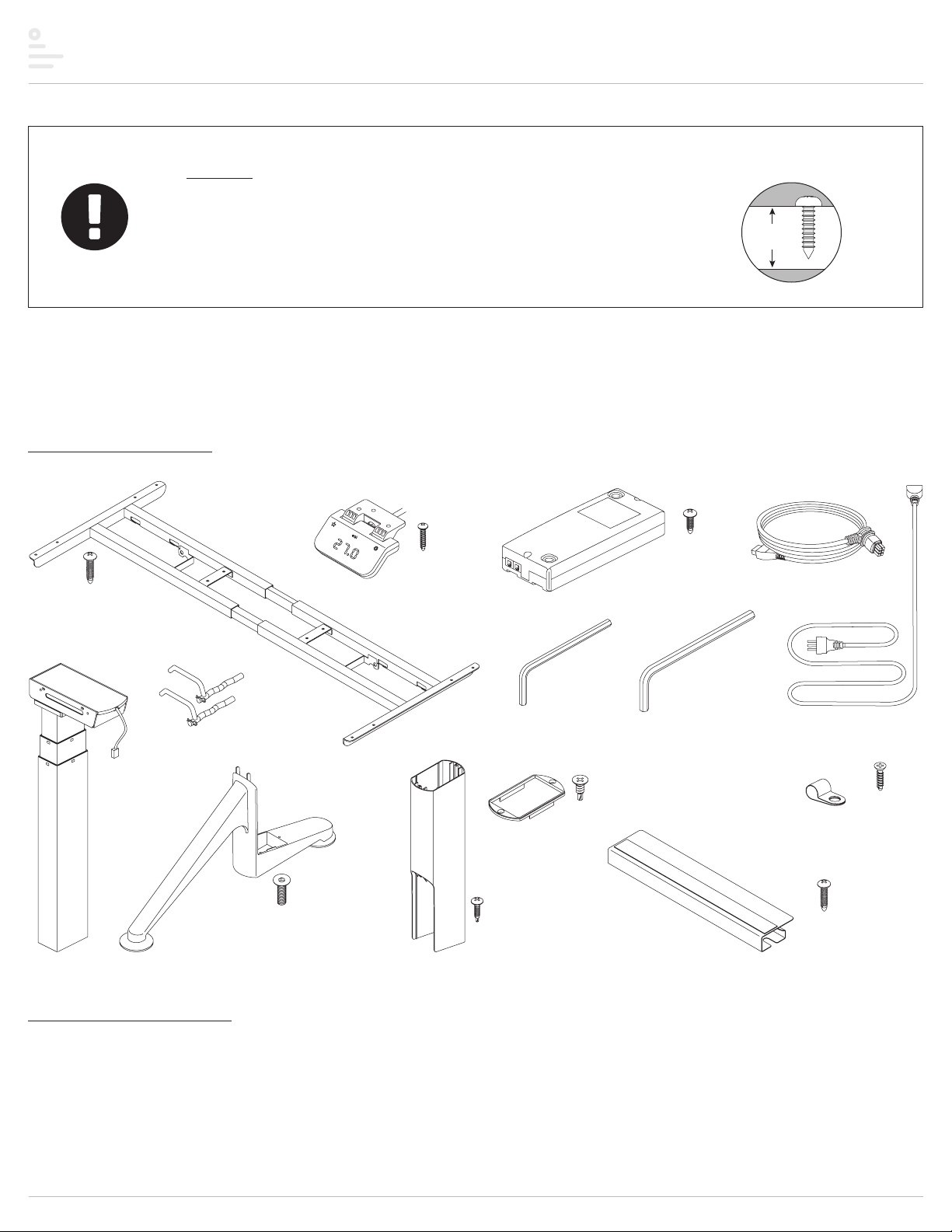
Brisa™ electric table base components and tools
work
surface
C48 frame (1)
control unit (1)
motor cable (2)keypad (1)
caution
• When drilling holes for the wood screws, guard against drilling through the
top of the worksurface.
• Always check that screws used to attach components to the worksurface
are not too long for the thickness of the surface.
Please review these instructions before beginning the installation. Use the illustrations below to check that the all components needed for your
installation were provided with your order. Do not discard the packaging until the product works to your satisfaction.
components and tools
round head (12)
M4.8x22
#2 Phillips
legs with
motor (2)
cam locks (2)
with cotter pin
feet (2)
M6x22 socket
flat head (8)
round head (3)
shroud (2)
M3x18.5
#1 Phillips
leg caps (2)
M4x15
#2 Phillips
round head (2)
4mm
Allen key (1)
#8-18x½"
#2 Phillips
flat head (4)
M5x15
#2 Phillips
round head (2)
5mm
Allen key (1)
cord-organizing
trough (2)
power cable (1)
cord clips (10)
M3.5x16
#2 Phillips
flat head (10)
M4.8x22
#2 Phillips
round head (6)
additional tools required
• power drill with assorted drill bits
• Phillips screwdriver
• Phillips #1 and #2 bits
Page 2
Page 3

Brisa™ electric table base assembly
1" with 24" table
step 1: position frame on table
With the table top facing down on a soft, clean surface, arrange the frame as shown below. The short end of the top supports must be toward the rear.
• Position the frame side to side.
— Loosen all eight set screws using the 5mm Allen key. Expand or compress the frame so that the top supports are 1" from the edges of the table. There are scribe
marks on the expanding portion of the cross channels; center the longest scribe mark. Then tighten the eight set screws.
• Position the frame front to back.
— With tables that are 24" deep, position the rearmost hole on the top supports 1" from the rear edge of the table. With 30" tables, position the rearmost holes 4" from
the rear edge of the table. This position of the frame will center the feet front to rear when they are installed in step 5.
short end toward rear
1"
top
support
center longest
scribe mark
step 2: screw frame to table
• Use the M4.8x22 #2 Phillips round head screws
(12 screws total).
• Screw through the top supports and cross
supports, as shown.
rear
M10 x 25
socket set screw
front
4" with 30" table
cross channel
loosen
set screws
feet
will be
centered
front
to rear
1"
M4.8x22
#2 Phillips
round head (12)
top support
cross support
Page 3
Page 4

Brisa™ electric table base assembly
step 3: attach legs to frame
• Remove the cotter pin from each cam lock and save it for use later in this step.
• Position each leg.
— First lower the protrusions on the motor housing into the notches.
— Then push the protrusions back toward the top supports into the narrower part of the notches.
• Route the motor cable on each leg under the frame support, as shown.
• Install the cam lock. With the lever arm upward, insert the long end of the cam lock first, as shown.
• After the cam lock is installed, rotate its lever arm toward the leg until the lever is horizontal. This locks the
leg in place.
• Install the cotter pin to secure the cam lock.
• Check to be sure each leg is securely locked in position.
cam lock
cotter pin
WARNING: The cam locks must be in the locked position at all times to secure the
legs in place.
position leg
install cam lock,
long end first
route motor
cable under
frame support
step 4: attach leg caps to shrouds
• Secure a leg cap to the top of each shroud with the self-tapping #8-18x½” #2 Phillips flat head screws.
leg cap
remove and save
rotate lever
to lock leg
secure
with cotter pin
#8-18x½"
#2 Phillips
flat head
Page 4
shroud
Page 5

Brisa™ electric table base assembly
step 5: insert shroud assemblies over legs
• Slide the shroud assemblies over the legs with the cutout
portion of the shroud toward the front, as shown.
• Lower the shroud all the way down to the motor end of
the legs.
cutout
faces front
shroud assembly
installed
shroud
step 6: attach feet to legs
• Attach the feet to the legs using the 4mm Allen key
and four M6x22 socket flat head screws per foot.
• The angled part of the foot faces front, as shown.
angled part
toward front
4mm Allen key
M6x22
socket flat head
Page 5
Page 6

Brisa™ electric table base assembly
step 7: attach shrouds to feet
• Raise each shroud up to the foot. Be sure the edges of the shroud are flush with the edges of the foot.
• Attach the shroud with one M4x15 #2 Phillips pan head screw per foot. The screw is self-tapping; use sucient torque to tighten it securely, but be careful not to strip
the shroud extrusion.
M4x15
#2 Phillips
round head (2)
shroud flush
with foot
Page 6
Page 7

Brisa™ electric table base assembly
step 8: attach cord-organizing troughs
• Two troughs may be installed to help organize the cords and
cables.
• Peel the backing from the double-sided tape on the bottom of
the troughs. Center the troughs at the rear of the table against
the frame cross channel.
• Secure each trough with three M4.8x22 #2 Phillips round head
screws.
M4.8x22
#2 Phillips
round head
trough
rear of
table
double-sided tape
installed troughs
step 9: attach keypad
• Install the keypad on the left or right side of the table, according to user preference.
• Position the back of the keypad 11/8" from the front edge of the table, as shown below.
• Attach the keypad using the three M3x18.5 #1 Phillips round head screws.
M3x18.5
#1 Phillips
round head
keypad
11/8"
11/8"
Page 7
Page 8

Brisa™ electric table base assembly
step 10: attach control unit
• Place the control unit between the cross channels. Position it so that the
cable from the keypad can reach the control unit and the motor cables can
extend from the control unit to both motors.
• Attach the control unit using the two M5x15 #2 Phillips round head screws.
control
unit
M5x15 #2 Phillips
round head
step 11: make connections and organize cables and cords
While making the following connections, organize the cables and cords using the troughs and the provided
cord clips. The cables and cords must not dangle under the table where they may present a hazard
to the user or may accidentally be pulled from their connections.
• Connect the cable from the keypad to one of the end ports on the control unit,
as shown.
• Connect the motor cables to the ports on top of the control unit and to the short
cable from each table leg.
• Connect the power cord to the control unit.
• Plug the power cord into an AC outlet. Be sure the cord can reach the outlet
when the table is raised to its highest position.
CAUTION: Do not operate the table until after initializing the system.
See step 12 on the next page.
trough
motor
cable
keypad
cable
cord clip
motor
cable
power cord
M3.5x16
#2 Phillips
flat head
Page 8
Page 9

Brisa™ electric table base assembly
keypad
step 12: use keypad to initialize the system
• Press and hold the star and gear buttons simultaneously for more than six
seconds. The legs will begin to move down at half the speed of normal operation.
• Continue to press the star and gear buttons. The legs will move down to the
lowest position, then rebound approximately 1/16" (2mm) and stop.
• Release the star and gear buttons at the same time. This completes the
initialization procedure.
star
button
IMPORTANT: The initialization procedure above must be completed
before operating the table.
NOTE: The unit must be re-initialized anytime power is cut to the unit.
step 13: test operation
• The keypad works like a lever switch. Press the lever down or lift it up to test operation.
— Release the lever to stop movement of the table. The table must stop prior to reversing direction.
• End your test with the legs lowered and then unplug the power cord.
• If there are problems with operation, check that all cable and cord connections are secure. If problems continue, call ESI Customer Service.
gear
button
move lever to
test operation
step 14: turn the table upright
With the assistance of a helper, turn the table upright and place it in its final position. IMPORTANT: There must be 1" (25mm) of clearance on all sides
of the worksurface (and other moving parts) to ensure free, unobstructed movement.
• If necessary, adjust the leveling glides on the feet to level the worksurface.
• Plug the power cord into an AC outlet.
• Re-initialize the table as described in step 12. IMPORTANT: Be sure there are no obstacles under the table that would prevent it from reaching its lowest position.
• See the operating procedures beginning on page 10.
Page 9
Page 10

Brisa™ electric table base operation
star
button
lift up or press downkeypad lever
LED height display
(inches or centimeters)
general operation
• Move the table by lifting the lever up to raise it or pressing the lever down
to lower it.
• The table will continue to move up or down until you release the lever or
until the maximum or minimum height is reached.
Table movement stops when you release the lever.
NOTE: The table must stop prior to reversing directions.
memory stop positions
Two memory stop positions can be used to save specific heights of the
worksurface. To set a specific position:
• Raise or lower the table to the first position you want to save.
• Touch the star button for more than three seconds and then release.
— The LED display flashes and stop position #1 is saved.
• Raise or lower the table to the second position you want to save.
• Touch the star button for more than three seconds.
— The LED display flashes and stop position #2 is saved.
If you try to set a third memory position, you will reset position #2.
To move the worksurface to a memory stop position:
• Lift or press the lever until the table stops. Release the lever.
— If you continue to lift or press the lever after it stops, the table will
continue to move up or down.
If you release the memory button before the saved position is reached, table
movement will stop.
To delete a memory stop position:
• Move the worksurface to the memory stop position you wish to delete.
• Touch the star button for more than three seconds.
— The LED display flashes. Release the star button.
— The stop position is deleted.
To delete both memory stop positions at the same time:
• Touch the star button for more than eight seconds.
— The LED display flashes and will show “CLr”.
— Release the star button. Both stop positions are deleted.
gear
button
CAUTION: The initialization procedure
must be completed before operating
the table. See Step 12 on page 9.
top height limit
To set the top height limit (the maximum height of the table):
• Use the lever to move the table to the desired maximum height.
• Touch the gear button six times. The display reads “F01”.
• Lift or press the lever until the display reads “F03”.
• Touch the gear button for three seconds. The display reads “–L–”.
— Release the gear button. The top height limit is set.
If there is a memory stop position higher than the top height limit, the
memory stop will be erased.
To erase the top height limit:
• Use the lever to move the table to any position.
• Touch the gear button six times. The display reads “F01”.
• Lift or press the lever until the display reads “F04”.
• Touch the gear button for three seconds. The display reads “–C–”.
— Release the gear button. The top height limit is erased.
If there was a memory stop position higher than the top height limit, the
memory stop needs to be set again.
bottom height limit
To set the bottom height limit (the minimum height of the table):
• Use the lever to move the table to the desired minimum height.
• Touch the gear button six times. The display reads “F01”.
• Lift or press the lever until the display reads “F05”.
• Touch the gear button for three seconds. The display reads “–L–”.
— Release the gear button. The bottom height limit is set.
If there is a memory stop position lower than the bottom height limit, the
memory stop will be erased.
To erase the bottom height limit:
• Use the lever to move the table to any position.
• Touch the gear button six times. The display reads “F01”.
• Lift or press the lever until the display reads “F06”.
• Touch the gear button for three seconds. The display reads “–C–”.
— Release the gear button. The bottom height limit is erased.
If there was a memory stop position lower than the bottom height limit, the
memory stop needs to be set again.
Page 10
Page 11

Brisa™ electric table base operation
height display units
To change the height display from inches to centimeters:
• Touch the gear button six times. The display reads “F01”.
• Lift or press the lever once. The display should continue to read “FO1”.
• Touch the gear button for three seconds. The height of the table is now
displayed in centimeters
— Release the gear button. The height display change from inches to
centimeters is complete.
To change the height display from centimeters to inches:
• Touch the gear button six times. The display reads “F01”.
• Lift or press the lever until the display reads “F02”.
• Touch the gear button for three seconds. The height of the table is now
displayed in inches.
— Release the gear button. The height display change from centimeters to
inches is complete.
adjusting the height readout
To set the display height of the table to account for dierent
worksurface thicknesses:
• Use the lever to move the table to the lowest position.
• Measure and record the height of the top of the worksurface in inches or
centimeters.
• Touch the gear button six times. The display reads “F01”.
• Lift or press the lever until the display reads “F09”.
• Touch the gear button once. The display reads “058”. The first number (“0”)
flashes.
• If necessary, lift the lever to increase the first number to match your
measurement.
— If the display height is in centimeters, the first number remains zero
(assuming the table is in the lowest position).
— If the display height is in inches, the first number will be the “tens”
column. (Example: If your measurement is 24”, the first number will
be “2”.) Lift the lever to increase the first number to “2”.
• Touch the gear button once. The second number (“5”) flashes.
• If necessary, lift or press the lever to increase or decrease the second
number to match your measurement.
• Touch the gear button once. The third number (“8”) flashes.
• If necessary, lift or press the lever to increase or decrease the third number
to match your measurement.
— If the display height is in inches, the third number will be either “0” or “5”.
(The “5” equals ½” — see note below.)
• Touch the gear button for three seconds. The height adjustment is complete.
In inch format, the minimum adjustable amount (third digit) is 0.5”. (The third
digit will be either 0 or 5.) In centimeter format, the minimum adjustable
amount (third digit) is 1 cm. (The third digit will be 0 through 9.)
leveling
To correct the gravity reference:
• Touch the gear button six times. The display reads “F01”.
• Lift or press the lever until the display reads “F12”.
• Touch the gear button for three seconds. Current mounting position angle
is displayed.
• Gravity reference is complete.
gyro anti-collision sensitivity adjustment
The default anti-collision sensitivity is G-1. To increase or decrease the
sensitivity of the table to obstacles in the path of its movement:
• Touch the gear button six times. The display reads “F01”.
• Lift or press the lever until the display reads “F10”.
• Touch the gear button once. The display reads “G-4”.
• Lift or press the lever to increase or decrease the sensitivity level.
— There are five levels of sensitivity: “G-0”, “G-1”, G-2”, “G-3” and “G-4”.
— “G-4” is the highest level of sensitivity and “G-0” is no gyro sensitivity.
• Touch the gear button for three seconds. The anti-collision sensivity
adjustment is complete.
If the legs do not move when general operation is attempted, the gyro
sensitivity adjustment may be too high.
error codes
Error
Code
E01 Leg malfunction
E03
E04
E06
E12 Gyro error
Description Troubleshooting
1. Check that the leg cables are securely plugged
into the leg and control unit.
2. Inner parts of leg are broken. Replace the leg.
Table top
overload
Control unit
malfunction
Communication
interruption
1. Remove some weight from the table.
1. Re-initialize the system.
1. Check the cable connection between the keypad
and control unit. Verify that the cable is securely
plugged into the control unit.
2. If the problem is not resolved, replace the keypad
or control unit.
1. Communication is abnormal; power ON to
normalize communication.
2. Table is tilted; straighten table or wait one minute
before operating table.
IMPORTANT: The table should be re-initialized after every 1,000 cycles; every six months; or if power is cut or cable is unplugged accidentally.
When re-initializing, be sure there are no obstacles under the table that would prevent it from reaching its lowest position
Page 11
Page 12

Brisa
™
electric table base
Please contact Customer Service with any questions or
comments at 800.833.3746 or visit our website at esiergo.com
LIMITED WARRANTY
ESI warrants this product to be free from defects in manufacturing for a period of 15 years on structural parts and 7 years on electrical parts from the date of original purchase. This warranty
extends only to the original purchaser, and does not apply if the product has been damaged or fails to function properly as a result of misuse, abuse, modification, alteration, or improper cleaning or
maintenance. This warranty does not apply to damage in shipment caused by carriers, damage caused during installation, normal wear and tear, or excessive use (meaning consistent use in excess
of an eight hour shift). ANY IMPLIED WARRANTIES OF MERCHANTABILIT Y OR FITNESS FOR A PARTICULAR PURPOSE ARE LIMITED IN DURATION TO ONE YEAR FROM THE DATE OF ORIGINAL RETAIL
PURCHASE. ESI’s sole obligation under this warranty or any implied warranty, and the purchaser’s sole remedy, is limited to the repair or replacement, at ESI’s option, of the product or any defec tive
part. Costs (such as installation, labor fees or express shipping) incurred due to replacement of products are not covered under warranty. IN NO EVENT SHALL FELLOWES, ITS AFFILIATES, SUBSIDIARIES,
RELATED ENTITIES OR THEIR RESPECTIVE OFFICERS, DIRECTORS, OR EMPLOYEES, BE LIABLE FOR INCIDENTAL, CONSEQUENTIAL, PUNITIVE, EXEMPLARY, OR SPECIAL DAMAGES.
To make a warranty claim, contact ESI at 800-833-3746 or customerservice@esiergo.com. You must provide proof of purchase, such as the original purchase order number.
The duration, terms and conditions of this warranty are valid worldwide, except where dierent limitations, restrictions or conditions may be required by local law.
BR Rev B 5/2019© 2019 Fellowes, Inc.
 Loading...