


OPERATING INSTRUCTIONS AND PARTS LIST
INSTRUCCIONES DE OPERACIÓN Y LISTA DE PIEZAS
TILE MASTER XL
Model: TM1-XLHT
0AF04028
Copyright © May, 2002 DBInc.
Printed in U.S.A.
17400 W. 119th Street
Olathe, Kansas 66061
Customer Service......800-365-4003
Corporate Office........913-928-1000
Cust. Service Fax......800-825-0028
Corporate Office Fax..913-438-7951
1

2

EVERY MACHINE IS THOROUGHLY TESTED BEFORE LEAVING THE FACTORY. EACH MACHINE
IS SUPPLIED WITH A COPY OF THIS MANUAL. OPERATORS OF THIS EQUIPMENT MUST READ
AND BE FAMILIAR WITH THE SAFETY WARNINGS. FAILURE TO OBEY WARNINGS MAY RESULT
IN INJURY OR DEATH. FOLLOW INSTRUCTIONS STRICTLY TO ENSURE LONG SERVICE IN
NORMAL OPERATION.
CONTENTS
Symbol Definitions ...............................................................................................................................4 - 6
Decal Descriptions and Locations .......................................................................................................8 - 9
Safety Warnings - DOs & DO NOTs ....................................................................................................10 - 11
Reference Figure 1 .............................................................................................................................12
Instructions:
1. Features ................................................................................................................................13
2. Benefits .................................................................................................................................13
3. Machine Set-Up Procedures .................................................................................................13 - 14
4. Operating Procedures ........................................................................................................... 14 - 15
5. Manual Thermal Overload ...................................................................................................... 15
6. Extension Cords .................................................................................................................... 15
7. Alignment Procedures ...........................................................................................................15 - 16
8. Profile Wheel Set-Up ............................................................................................................ 16
9. Maintenance.......................................................................................................................... 16
10. Water Pump, Trouble Shooting Procedure ............................................................................16
11. Repairs .................................................................................................................................17
12. Spare Parts ...........................................................................................................................17
13. Accessories .......................................................................................................................... 17
Diagrams and Spare Parts ..................................................................................................................28 - 29
Wiring Diagrams .................................................................................................................................30 - 32
Warranty .............................................................................................................................................33
ANTES DE SALIR DE NUESTRA FÁBRICA, CADA MÁQUINA ES SOMETIDA A PUREBAS
DETENIDAS. CADA MÁQUINA DE CORTE ES ENTREGADA CON UNA CIPIA DE ESTE MANUAL.
LOS OPERARIOS DE ESTOS EQUIPOS DEBEN LEER Y FAMILIARIZARSE CON LAS
INSTRUCCIONES DE SEGURIDAD. EL NO PRESTAR ATENCIÓN A ESTAS ADVERTENCIAS
PUEDE OCASIONAR GRAVES LESIONE. SIGA ESTRICAMENTE NUESTRAS INSTRUCCIONES
Y SU MÁQUINA LE VA A PRESTAR LARGOS AÑOS DE SERVICIO EN CONDICIONES NORMALES
DE UTILIZACIÓN.
CONTENIDO
Definición De Los Simbolos ................................................................................................................4 - 6
Descripción De Calcamonias Y Ubicaciones .....................................................................................8 - 9
Advertencias De Seguridad HACER & NO HACER ............................................................................. 18 - 19
Figura 1 De Referencia .......................................................................................................................20
Instrucciones:
1. Caracteristica ......................................................................................................................21
2. Beneficio .............................................................................................................................21
3. Instalacíon De La Cortadora ............................................................................................... 22 - 23
4. Instrucciones De Operación ................................................................................................23
5. Protector Térmico - Rearmado Manual ................................................................................ 24
6. Cables De Extensión ...........................................................................................................24
7. Procedimientos de Alineacion ............................................................................................. 24
8. Armado y Uso de la Rueda Perfiladora ............................................................................... 25
9. Instrucciones De Mantenimiento ......................................................................................... 25
10. EnCaso De Problemas Con La Bomba De Agua................................................................. 25
11. Reparaciones ......................................................................................................................26
12. Piezas De Recambio ...........................................................................................................26
13. Accesorios .......................................................................................................................... 27
Diagrame y Piezas De Recambio ........................................................................................................ 28 - 29
Diagrame De Cablado Eléctrico ..........................................................................................................30 - 32
Garantia ...............................................................................................................................................33
3

Symbol Definitions
Definición De Los Simbolos
• Please read the instructions for use prior to operating the machine for the first time.
• Antes de la puesta en marcha, lea detenidamente las instrucciones y familiaricese con la máquina.
• Mandatory
• Obligatorio
• Indication
• Indicación
• Prohibition
• Prohibición
• Warning Triangle
• Triángwulo De Advertencia
• Wear Eye Protection
• Usar Gafas De Protección
• Wear Head Protection
• Usar Casco De Protección
• Wear Breathing Protection
• Usar Máscara De Protección
• The Use Of Ear Protection Is Mandatory
• Es Obligatorio El Uso De Protección Auditiva
• Wear a Hard Hat
• Usar Casco Duro
• Wear Safety Shoes
• Usar Zapatos De Seguridad
• Wear Appropriate Clothing
• Usar Ropa Adecuada
• Remove The Blade Prior To Hoisting, Loading, Unloading And Transporting The Machine On Jobsite.
• Desmontar El Disco Antes De Desplazar, Cargar, Descargar O Transportar La Máquina En La Obra.
4

• Motor Off
• Parar El Motor
• Use In Well Ventilated Area
• Usar En Una Área Bien Ventilada
• Do Not Use In Flammable Areas
• No Usar In Áreas Inflamables
• Machinery Hazard, Keep Hands And Feet Clear.
• Máquina Peligrosa - Mantenga Manos Y Pies Alejados De La Máquina
• No Non-working Personnel In Area
• Prohibido Para Personas Ajenas A La Obra
• No Smoking
• No Fumar
• Do Not Operate Without All Guards In Place
• No Operar Sin Todas Las Protecciones In Su Sitio
• Always Keep the Blade Guards In Place
• Mantenga Siempre Las Protecciones De La Hoja En Su Sitio
• Keep Work Area Clean/Well Lit, Remove All Safety Hazards
• Mantenga Limpio El Sitio De Trabajo/Bien Iluminado, Elimine Todos Los Riesgos De Seguridad
• Dangerously High Noise Level
• Nivel De Ruido Elevadamente Peligroso
• Pay Extreme Attention To The Care And Protection Of The Machine Before Starting Up
• Ponga Extrema Atención Al Cuidado Y Preparación De La Máquina Antes De Ponerla En Marcha
• Remove Tools From Area and Machine
• Elimine Las Herramientas Del Área Y De La Máquina
• Electrical Switch - OFF
• Conmutador De Apagado Eléctrico
• Electrical Switch - ON
• Conmutador De Encendido Eléctrico
• Electrical Switch - Start
• Conmutador De Arranque Eléctrico
• Repairs Are To Be Done By An Authorized Dealer Only
• Las Reparaciones Deben Ser Efectuadas Únicamente Por Un Distribuidor Autorizado
5
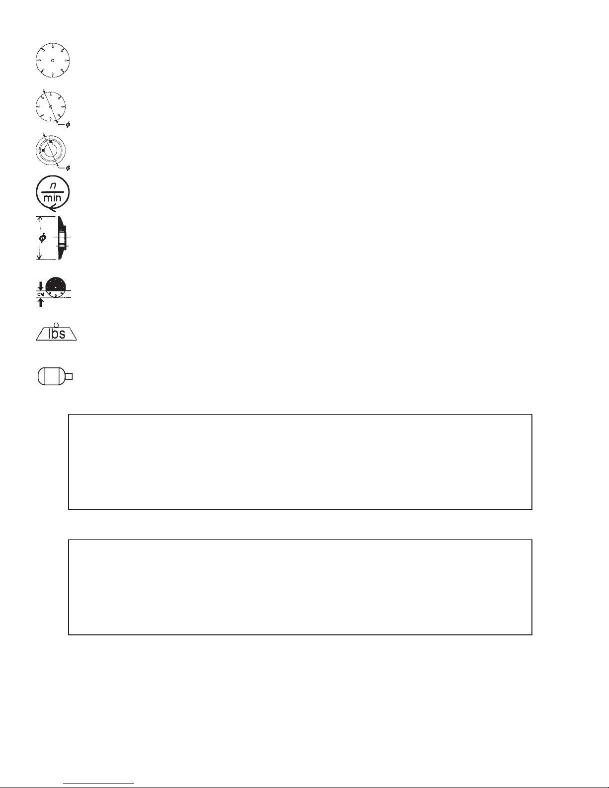
• Diamond Blade
• Sierra Diamantada
• Blade Diameter
• Diámetro De La Hoja
• Pulley Diameter
• Diámetro De La Correa
• Number of Revolutions Per Minute, Rotational Speed
• N° De Revoluciones Por Minuto, Velocidad De Rotación
• Blade Flange Diameter
• Diámetro De La Brida De La Hoja
• Blade Cutting Depth
• Profundidad De Corte De La Hoja
• Machine Mass (lbs)
• Masa De La Máquina (lbs)
• Electric Motor
• Motor eléctrico
WARNING
HEARING HAZARD
DURING NORMAL USE OF THIS MACHINE, OPERATOR MAY BE EXPOSED TO A NOISE
LEVEL EQUAL OR SUPERIOR TO 85 dB (A)
ATENCION
RIESGO DE DAÑO AUDITIVO
EN CONDICIONES NORMALES DE UTILIZACIÓN, EL OPERADOR DE ESTA MÁQUINA PUEDE
ESTAR EXPUESTO A UN NIVEL DE RUIDO IGUAL O SUPERIOR A 85 dB (A)
6

NOTES:
7
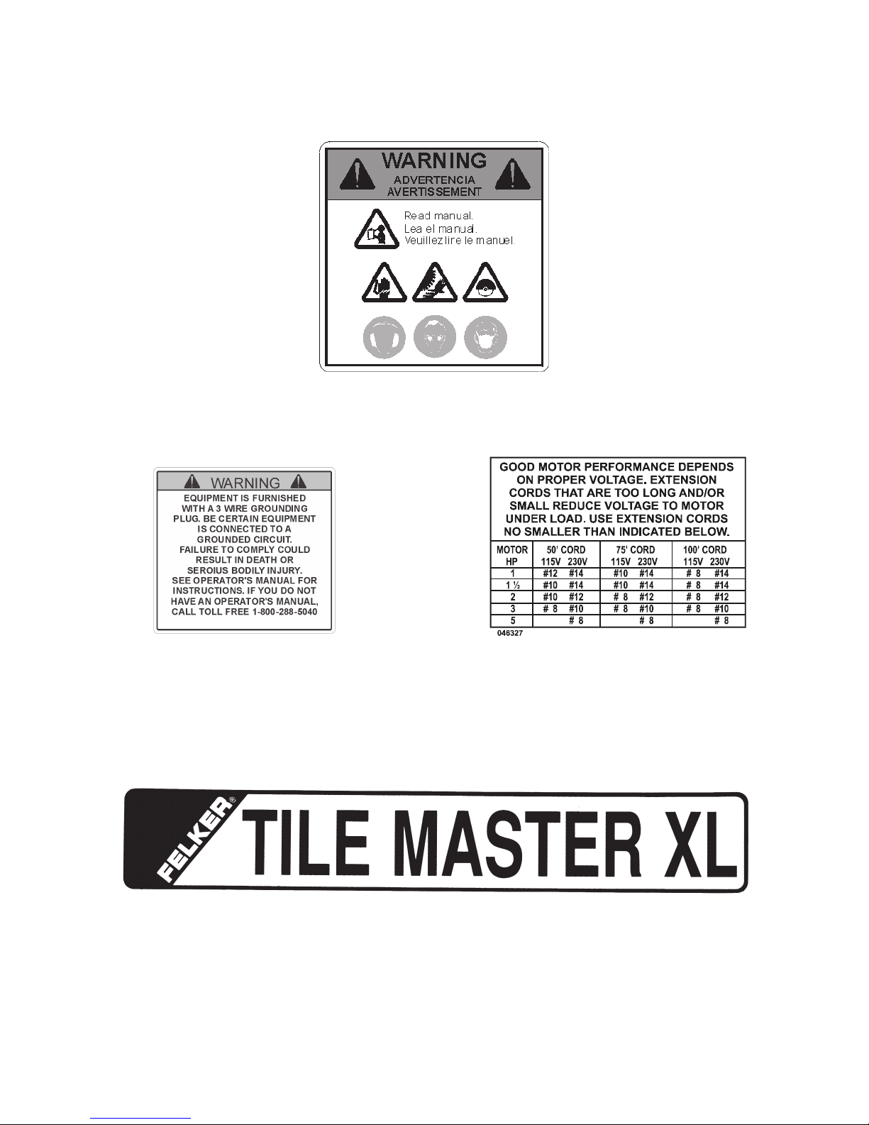
DECAL DESCRIPTIONS & LOCATION
DESCRIPCIÓN DE CALCAMONIAS Y UBICACIONES
P/N 187043
Location: Top of Belt Guard
P/N 046326
Location: Motor Assembly
P/N 046327
Location: Motor Assembly
P/N 169265
Location: Front of Water Pan
8

DECAL DESCRIPTIONS & LOCATION
DESCRIPCIÓN DE CALCAMONIAS Y UBICACIONES
P/N 161459
Location: Water Pan Sides
P/N 169281
Location: Side of Belt Guard & Side of Blade Guard
P/N 189025 - Outer P/N 189026 - Inner
Location: Blade Guard
P/N 189027
Location: Belt Guard
9

SAFETY FIRST!
WARNINGS
DO’s AND DO NOT’s
WARNING:
FAILURE TO COMPLY WITH THESE WARNINGS AND OPERATING
INSTRUCTIONS COULD RESULT IN DEATH OR SERIOUS BODILY INJURY.
DO
DO read this entire operator’s manual before operating this machine. Understand all warnings, instructions, and controls.
DO keep all guards in place and in good condition.
DO wear safety approved hearing, eye, head and respiratory protection.
DO read and understand all warnings and instructions on the machine.
DO read and understand the symbol definitions contained in this manual.
DO keep all parts of your body away from the blade and all other moving parts.
DO know how to stop the machine quickly in case of emergency.
DO turn the “ON/OFF” switch to the “OFF” position prior to connecting the machine to the power source.
DO inspect the blade, flanges and shafts for damage before installing the blade.
DO use the blade flange size shown for each blade size.
DO use only the blade flanges supplied with the saw. Never use damaged or worn blade flanges.
DO use only blades marked with a maximum operating speed greater than the blade shaft speed. Verify speed by checking
blade shaft rpm and pulley diameters and blade flange diameters.
DO verify saw drive configuration by checking blade shaft RPM, pulley diameters, and blade flange diameter.
DO read all safety materials and instructions that accompany any blade used with this machine.
DO inspect each blade carefully before using it. If there are any signs of damage or unusual wear, DO NOT USE THE
BLADE.
DO mount the blade solidly and firmly. Wrench tighten the arbor nut.
DO make sure the blade and flanges are clean and free of dirt and debris before mounting the blade on the saw.
DO use the correct blade for the type of work being done. Check with blade manufacturer if you do not know if blade is
correct.
DO use caution and follow the instructions when loading and unloading the machine.
DO operate this machine only in well ventilated areas.
DO instruct bystanders on where to stand while the machine is in operation.
DO establish a training program for all operators of this machine.
DO clear the work area of unnecessary people. Never allow anyone to stand in front of or behind the blade while the motor
is running.
DO make sure the blade is not contacting anything before starting the motor.
DO use caution when lifting and transporting this machine.
DO always tie down the machine when transporting.
DO use caution and follow instructions when setting up or transporting the machine.
DO have all service performed by competent service personnel.
DO make sure electric powered machines are plugged into a properly grounded circuit.
DO make sure power cords are the proper size and in good condition.
DO maintain a secure grip on the material being cut.
DO clean the water tray frequently.
DO verify the blade arbor hole matches the machine spindle before mounting the blade.
DO clean the machine after each day’s use.
DO follow all electrical codes in your area.
DO consider work area environment. Don’t expose power tools to rain. Don’t use power tools in wet locations.
DO use caution to guard against electric shock. Prevent body contact with grounded surfaces (i.e., pipes, radiators, ranges,
refrigerators).
DO use correct voltage and proper extension cords. Never carry tool by cord or yank it to disconnect it from receptacle. Keep
cord away from heat, oil and sharp edges.
DO always carry the machine with the motor stopped.
DO disconnect tools from power source when not in use, before servicing and when changing accessories.
DO carefully maintain and clean for better and safer performance. Follow instructions for changing accessories. Inspect tool
cords periodically and, if damaged, have repaired by authorized service facility.
DO only cut in a straight line.
DO only saw as deep as the job specifications require.
DO always give a copy of this manual to the equipment user. If you need extra copies, call TOLL FREE 1-800-365-4003.
10

SAFETY FIRST!
WARNINGS
DO’s AND DO NOT’s
WARNING:
FAILURE TO COMPLY WITH THESE WARNINGS AND OPERATING
INSTRUCTIONS COULD RESULT IN DEATH OR SERIOUS BODILY INJURY.
DO NOT
DO NOT operate this machine unless you have read and understood this operator’s manual.
DO NOT operate this machine without the blade guard, or other protective guards in place.
DO NOT stand behind or in front of the blade path while the motor is running.
DO NOT leave this machine unattended while the motor is running.
DO NOT operate this machine when you are tired or fatigued.
DO NOT use a wet blade without adequate water supply to the blade.
DO NOT exceed maximum blade speed shown for each blade size. Excessive speed could result in blade breakage.
DO NOT operate the machine if you are uncertain of how to run the machine.
DO NOT use damaged equipment or blades.
DO NOT touch or try to stop a moving blade with your hand.
DO NOT cock, jam, wedge or twist the blade in a cut.
DO NOT transport a cutting machine with the blade mounted on the machine.
DO NOT use a blade that has been dropped or damaged.
DO NOT use carbide tipped blades.
DO NOT use abrasive blades.
DO NOT use conventional abrasive blades with water.
DO NOT touch a dry cutting diamond blade immediately after use. These blades require several minutes to cool after
each cut.
DO NOT use damaged or worn blade flanges.
DO NOT allow other persons to be near the machine when starting or when the machine is in operation.
DO NOT operate this machine in an enclosed area unless it is properly vented.
DO NOT operate this machine in the vicinity of anything that is flammable. Sparks could cause a fire or an explosion.
DO NOT allow blade exposure from the guard to be more than 180 degrees.
DO NOT operate this machine with the belt guard or blade guard removed.
DO NOT operate this machine unless you are specifically trained to do so.
DO NOT use a blade that has been over heated (Core has a bluish color).
DO NOT jam material into the blade.
DO NOT grind on the side of the blade.
DO NOT lay power cords in or near the water.
DO NOT replace the motor with any motor that does not have a special grounding connection.
DO NOT cut deeper than 1" per pass with a dry blade. Step out to achieve deeper cuts.
DO NOT start cutting with a saw until you have a clear work area and secure footing.
DO NOT operate this machine while using drugs or alcohol.
This saw was designed for certain applications only. DO NOT modify this saw or use for any application other
than for which is it was designed. If you have any questions relative to its application, DO NOT use the saw until
you have written Diamant Boart, Inc. and we have advised you.
*****************
Diamant Boart, Inc.
17400 West 119th Street
Olathe, Kansas 66061
In USA 1-800-365-4003
11

FIGURE 1
A. Set Collar
B. Bearing Caps
C. Locking Knob
D. Lockbar
E. Water Pump
F. Hose Barb
G. Water Valve
H. Water Tube Assembly
I. Water Tube Ports
J. Blade Guard
K. Electrical Receptacle
L. Blade Shaft Nut
M. Outer Blade Flange
N. Wrench
1. Cutting Head Assembly: Includes water tube
assembly (H)}
2. Frame Assembly
3. Water Pan Assembly
4. Tow Cart Assembly Carton
5. Conveyor Cart Assembly Carton {Cart
Assembly (4) and Rip Guide (P)}
6. Water Pump and Accessory Carton: Includes
Water Pump (E), Hose Barb (F), Water Valve
(G), 15/16" Wrench (N), Drain Plug (P),
Locking Knob (C) with 5/16" Flatwashers,
Bearing Caps (B) w/ 5/16” Fasteners and Set
Collar (A).
O. Drain Plug
P. Rip Guide
Q. Water Pan Assembly Guides
12

MANDATORY
WARNING
INDICATION
INFORMATION
INSTRUCTION
PROHIBITION
Any persons not involved in the work should
leave the area.
Use only blades marked with a maximum
operating speed greater than the blade shaft
speed.
These signs will give
advice for your safety
Before leaving our factory every machine is
thoroughly tested.
Follow our instructions strictly and your machine will
give you long service in normal operating conditions.
1 FEATURES
Use: Sawing of any kind of tile, up to 27" (685mm)
diagonal on 18" x 18" (450 x 450 mm) tile.
Tools: Rip Guide comes standard on all tile saws. See
Tile Cutting Accessories on page 15.
(For information or availability of other accessories
contact your Felker supplier.)
Blade Capacity: Rim Ø 10" (254mm) - bore 5/8" (15,9mm).
Profile Wheel: Rim Ø 7" (180mm) - bore 5/8" (15,9mm).
Blade Rotation: Counter-Clockwise (CCW).
Depth of Cut: 3-3/4" (95mm) with 10" (254mm) blade.
Horsepower: 1-1/2 1-1/2 2
Voltage: 115 115/230 240
F.L. Amperages: 14.6 17.2/8.6 12
Blade Shaft RPM: 2760 3880 2850
Weight: lb. (kg.) 150 (68.2) 154 (70) 171 (77.7)
2 BENEFITS
• The new, improved blade guard offers simplified blade
installation and removal - maximum 10" (254mm) blade
capacity. The external water tube assembly is removable
for easy maintenance.
• 1-1/2 HP, High Torque (HT) 115V/60/1 motor on
standard saw.
• The dependable, high volume, submersible coolant
pump features a screened intake.
• The motor and pump power cords are securely mounted
directly into the Motor Housing (K).
• The removable Drain Plug (O) at the back end of the
pan permits easy coolant draining and quick sludge
clean out. The Water Pan (3) is removable for easy
cleaning.
• The free-rolling Conveyor Carts (4) are aligned for
straight, smooth cuts. The Back Stop with ruler allows
fast mounting and adjustment of the rip fence and
optional accessories.
• Full-size belt shield and belt protection.
• The special, rubberized surface coating extends cart
life and aids in control of work.
• Makes 25" diagonal cuts on 18" x 18" (450 x 450 mm)
tile.
• The adjustable pan allows the operator to cut tile
comfortably with a full view and control of work with
minimum stretching.
3 MACHINE SET-UP PROCEDURE
(See Figure 1)
Dimensions - L x W x H: in 51-1/4" x 25-3/4" x 19-3/4"
(cm) (130 x 65 x 50)
Conveyor Cart - with special rubberized surface.
L x W: in (mm) 10-1/4" x 16" (260 x 406)
Pan Holding Capacity: 12 gallons (46.1 liters)
Water Pump Output: 100 gal/hr. (378 l /hr.)
Before starting up the machine, make sure you
read this entire manual and are familiar with
the operation of this machine.
The working area must be completely clear, well
lit and all safety hazards removed.
The operator must wear
protective clothing
appropriate to the work he is
doing.
• Remove all items from the shipping carton and identify:
1. Cutting Head Assembly: Includes Water Tube
Assembly (H)
2. Frame Assembly
3. Water Pan Assembly
4. Conveyor Cart Assembly Carton {Cart Assembly
(4) and Rip Guide (P)}
5. Water Pump and Accessory Carton: Includes tile
markers, Water Pump (E), Hose Barb (F), Water
Valve (G), 15/16" Wrench (N), Drain Plug (O),
two Bearing Caps (B) and fasteners: [four each
of 5/16" flatwashers and fiber locknuts], Locking
Knob (C) and a 5/16" flatwasher.
6. Literature Assembly Envelope
NOTE: Check the carton and all packing filler for loose parts
and optional accessories (if ordered).
• Set the Frame Assembly (2) on a flat surface or on a
FELKER ® folding stand.
13

• Mount the water pan assembly Guides (Q) over the
Frame Assembly (2) legs between the vertical post and
the Sliding Pan Stop (R). The Pan Assembly (3) should
slide freely back and forth on the Guides (Q) with little
lateral movement. Adjust if needed.
• Install the Cart Assembly (4) with the Back Stop at the
operating end. Check that all four wheels are on the
rails and that it travels freely back and forth.
Install the Cutting Head Assembly (1):
1. Set the Cutting Head Assembly (1) on the pivot
bar up against the Set Collar (A). The set collar
has been pre-set at the factory to align the blade
with the slot in the center of the cart; it can be
adjusted if needed.
2. Install the two Bearing Caps (B) over the long
setscrews located in the bottom of the Cutting Head
(1) using 5/16" flatwashers and locknuts. Next,
tighten the locknuts so that the Cutting Head (1) is
held securely on the base pivot bar, but can be
adjusted up or down.
3. Insert the Locking Knob (C) with 5/16" flatwasher
through the slotted Lockbar (D) into the tapped
hole in the belt guard. This is used to set the
cutting depth of the blade.
Water Pump Assembly (5) Set-up:
1. Remove the Water Pump (E), Hose Barb (F), the
Water Control Valve (G) and Water Tube Assembly (H) from their carton. Thread the Hose Barb
(F) on the water pump outlet, hand tighten.
2. Slide the Control Valve (G) onto the flexible plastic
tubing and push the open end onto the Hose Barb
(F).
3. Set the Water Pump Assembly (5) in the deep
end of the pan beneath the belt guard. Note: The
water pump inlet screen must be submerged
in order to properly pick up water.
4. Place the Water Tube Assembly (H) to the back
of the Blade Guard (J) and insert the two 1/4"
plastic nozzles into the Ports (I) on the side of the
Blade Guard (J). To prevent interference with the
full movement of the cart, it is recommended that
the tubing and electrical cord exit out the back
through the indented area of the pan.
5. Insert the male plug into the Receptacle (K) on
the motor. The Water Pump (E) will start when
the motor is turned on. For dry cutting, the water
pump should be unplugged or removed to prevent
damage to the pump.
Install the Cutting Blade:
Always set the Motor Switch to OFF prior to
mounting the blade.
1. Be sure you are using the correct blade for the
material being cut. For example, blades are available for cutting materials such as wall tile, quarry
tile, marble, slate and similarly hard materials. For
the best results, always use genuine FELKER ®
diamond blades. Contact your nearest dealer to
14
select the correct blade for your specific cutting
needs.
2. Rotate the Blade Guard (J) fully up, tightening the
wing nut if needed to hold it in the fully raised
position.
3. Remove the Blade Shaft Nut (L) and the Outer
Blade Flange (M).
4. Check the blade for Counter Clockwise rotation
(CCW) and install on the spindle shaft.
Rotation direction is indicated by an arrow on
one side of the blade. Make sure the blade
contact surfaces are clean.
5. Install the outer flange with the large diameter
against the blade. Tighten the Blade Shaft Nut (L)
with the 15/16" Wrench (N) provided.
6. Lower the Blade Guard (J) and retighten the wing
nut to securely hold the guard in place.
• Install the Drain Plug (O) into the back end of the pan
and fill with clean water until inlet filter of water pump is
covered; about 12 gal. (46.1 l).
• Adjust the Pan Assembly (3) to accommodate the size
of the tile to be cut and to obtain the most comfortable
position for the operator.
1. When cutting smaller tile units, adjust the pan all
the way to the rear. The operator has full view
and control of the work with minimum stretching.
2. For cutting intermediate sized units, such as 8" or
10" tile, the pan can be placed somewhere between
the maximum forward and maximum rear positions.
3. When cutting larger units, the pan should be moved
to the maximum forward position, thus giving the
operator the best and most comfortable position, even
when cutting 18" x 18" or larger units.
4 OPERATING PROCEDURE
WARNING: Read the Operating Procedure
completely before operating your tile saw.
Take into account the working conditions from
the health and safety point of view.
Always pay extreme care and attention to the
preparation of the machine before starting.
Remove all wrenches and tools from the
machine.
Always keeps blade guard in place.
• Fill the Pan with enough water to fully submerge the
water pump screen. It takes approximately 12 gallons
(46.1 l.) to fill the Pan.
• Before connecting the power cord:
* Check the spindle nut to be sure it is tight and that
the blade rotates freely.

WARNING: Check that the ON/OFF switch is in
the OFF position. Then connect the power cord
to a properly grounded outlet of the correct
voltage. See the decal near the power cord for
power requirements. If needed, use the correct
size three (3) conductor extension cord to avoid
excessive voltage drop. Never use lamp cord
type extensions. Refer to the Recommended
Extension Cords chart below.
• Turn the switch to ON. The blade should turn counter-
clockwise, when looking at the blade guard side. The
water pump will start automatically when the motor
starts. Adjustment of the water supply may be made
by means of the Control Valve (G).
• Follow the blade manufacturer’s recommendations for
dry or wet cutting. Wet cutting blades can be damaged
or destroyed without sufficient water. Only blades
specifically designed for dry cutting can be used
without coolant.
The water supply should be adequate, with
water flowing on both sides of the blade. Keep
the water clean and make certain the WATER
LEVER IS ALWAYS ABOVE THE PUMP INLET.
Do not run the water pump dry!! Unplug for
dry cutting.
• For straight cuts, position the tile squarely against the
back edge of the conveyor cart. Keep the cart clean
and free of cuttings. The standard rip guide is used.
• Move the conveyor cart slowly and carefully until the
blade is in contact with the tile. The blade needs a
chance to “break-in” or “wear-in” slightly. It may take
about ten cuts to open a new blade for best cutting.
5 MANUAL THERMAL OVERLOAD
7 ALIGNMENT PROCEDURES
Your Tile Master XL tile saw is factory assembled and aligned
prior to shipment to ensure accurate cuts when your saw is
delivered. However, since FELKER® cannot control rough
handling during shipping, it is suggested that the alignment
be checked. If the saw is found in need of adjustment, refer
to the appropriate section(s) below.
There are two basic alignment checks for the Tile Master
XL and any adjustments made must follow these procedures
to ensure that the unit functions freely.
Adjustment tools required: Carpenter’s Square, two (2) 7/16"
wrenches, 1/2" wrench and 5/32" hex key.
1. Check the Blade in Slot Alignment
* The blade should be centered in the conveyor cart
slot.
* Set-up your saw as described above and move
the conveyor cart back and forth from the front to
the rear of the pan. If the blade contacts either
side of the slot, the Cutting Head Location
Adjustment must be performed.
Cutting Head Location Adjustment (See Figure)
* The Cutting Head Assembly is located between to
Set Collars (S). Using a 5/32" hex key, loosen
these two (2) set collars. Next, loosen the four (4)
5/16"-18 locknut nuts (1/2" wrench) that clamp
the bearing caps (B) to the Pivot Bar (T). Move
the Head Assembly along the bar until the blade
no longer contacts the slot. Re-locate the set
collars against the sides of the Cutting Head again
and retighten the set screws. Retighten the
locknuts on the bearing caps.
The motor is equipped with a manual overload protection
reset button. If the motors overheats, the red reset button
will “pop out” to open the motor circuit; stopping the motor
and water pump. If this occurs , the motor ON/OFF switch
must be set to OFF. After the motor cools, push in the reset
button. When it stays in, the motor can be restarted.
6 RECOMMENDED EXTENSION CORDS
Good motor performance depends on proper
voltage. Extension cords that are too long and/
or too small in wire gauge reduce the voltage
to the motor under load. Use extension cords
no smaller than indicated below.
MOTOR F.L. AMPS 50' Cord 75' Cord 100' Cord
HP RPM 115V 230V 115V 230V 115V 230V 115V 230V
1-1/2 1725 14.6 #12 #10 #8
1-1/2 3450 17.2 8.6 #10 #14 #10 #14 #8 #14
2 2850 12 #12 #10 #10
2. Check the Parallel Alignment (See Figure)
* The conveyor cart should travel parallel to the plane
of the blade.
* Place a square rule against the backstop, lightly
in contact with the blade. The blade surface should
be parallel to the square; i.e., no gap between the
blade and the square at either the front or back
edge of the blade. Next, holding the square firmly,
15

traverse the cart fore and aft. The blade should
remain parallel to the square, staying slightly in
contact with it throughout its full travel. If the blade
does not stay in contact with the square, the
Parallel alignment must be performed.
Parallel Alignment
* The parallel tracking of the cart can be adjusted
by moving the rails on which the cart travels. The
mounting holes in the pan and the Rail Support
(U) are slotted to accommodate this adjustment.
* Align the inside rail first. Loosen the four (8)
1/4"-20 fasteners (7/16" wrenches) locating the
two (2) Rails (R) so that both rails are free to move.
Move the end(s) of rail until the square is flush
with the blade as described above. Tighten the
fasteners of this rail and recheck the alignment.
Once alignment has been made, move the cart
fore and aft to locate the second rail parallel to
the first. Tighten the remaining fasteners.
8 PROFILE WHEEL SET-UP AND USE
The Tile Master XL is designed for use with a FELKER® 6"
Profile Wheel, such as P/N 621081 or 621082.
After each day’s use: CLEAN THE MACHINE!!
* Turn off and unplug the saw before performing
any maintenance.
* Keep the cart top clean and free for cuttings. To
clean it, flush the top surface and grooves with
water.
* Drain, clean and refill the pan frequently. Flush
the coolant system with plenty of water, then drain
and refill the pan.
* If the water flow stops, check the water pump to
see if the shaft and impeller turn freely. See the
WATER PUMP TROUBLE-SHOOTING
PROCEDURE section.
* It is always good practice to clean your tile saw
after each day’s use. Drain the water and clean
out the pan. Clean the rails. Before storing, it is
good practice to wipe or spray rails with
water-soluble oil (like, WD-40 or equivalent).
Entrust all repairs to your authorized dealer
only.
10 WATER PUMP TROUBLE-SHOOTING PROCEDURE
• Raise the blade guard. Remove the spindle nut and
outer flange. Remove the tile saw blade if one has
been installed.
• Install the profile wheel onto the spindle shaft up against
the inner flange with the working surface to the outside.
• Secure into place by reversing the outer flange and
tightening the spindle nut. Lower the Blade Guard (J)
back down over the profile wheel.
• Locate the material for profiling:
1. Set the edge of the part to be shaped parallel to
the wheel.
2. Locate the material under the wheel. Pull the
Conveyor Cart (4) with the material from under
the wheel to set proper cutting height.
3. Loosen the Locking Knob (C) and lower the Cutting
Head (1) so that the wheel just slightly makes
contact with the material.
4. Secure the Cutting Head (1) into position with the
Locking Knob (C) for cutting.
5. Note: Profiling usually takes several light passes
to produce the best results. Set lower each time
until the desire depth has been reached.
9 MAINTENANCE PROCEDURES
If Water Stops Flowing,
1. Stop Sawing, then
2. Disconnect Electrical Plug from Outlet, then
3. Remove the Pump, then
4. Back Flush.
Back flushing is done by forcing water into the pump discharge and out through the screen. Most of the time this
procedure works, and the pump can be put back into service. (See Figure below)
If the back flushing does not work, remove the screen and
turn the impeller manually, looking for and rinsing out the
impeller cavity of any dirt or foreign matter.
Before performing any maintenance, ALWAYS
place the machine on a level surface with the
motor OFF and disconnect the electrical
current. Let the machine cool down!!
Your FELKER® tile saw is a ruggedly constructed machine,
engineered to give long, satisfactory performance. Simple
daily maintenance and care will add to the life and productivity
of your saw.
16

11 REPAIRS
12 SPARE PARTS
We carry out all repairs in the shortest possible time and at
the most economical prices. (See front page for address
and phone numbers) Contact your authorized FELKER®
dealer concerning maintenance and repairs.
For quick supply of spare parts and to avoid any lost time, it
is essential to quote the data on the manufacturers plate
fixed to the machine and the part number(s) and description
to be replaced with every order.
13 TILE CUTTING ACCESSORIES
ANGLE GUIDE PROTRACTOR PRECISION MITERING GUIDE BULLNOSE FOLDING STAND
Parts List:
Diag. Part No. Qty. Description Diag. Part No. Qty. Description
1 161479 1 Frame, Miter 10 ———— 1 Protractor Arm
2 050107 1 Bar, Locking 11 020011 1 Bolt, Carriage, 1/4-20 x 5/8”
3 050105 1 Clip, Stop 12 020244 1 Wing Nut, 1/4-20
4 050106 1 Spring 13 020598 1 Screw, Thumb, 1/4-20 x 1”
5 050103 1 Knob 14 051010 1 Protractor Assy
6 020598 2 Screw, Thumb, 1/4" - 20 x 1" 15 020598 1 Screw, Thumb, 1/4" - 20 x 1"
7 051020 1 Miter Assy, 45
8 020598 1 Screw, Thumb, 1/4" - 20 x 1" 17 051041 1 Stand, Tile Saw
9 ———— 1 Protractor Head 18 050102 1 Support Assy, Miter Frame
RIP GUIDE: P/N 051000 - The Rip Guide is a standard
accessory supplied with every tile saw. It is used to provide
a repeatable position for rip cuts until relocated. The Rip
Guide clamps to the machined backstop of the conveyor cart.
ADJUSTABLE PROTRACTOR: P/N 051010 - The Protractor
can be used to rip cut known angles. The protractor clamps to
the backstop.
ANGLE GUIDE : P/N 051020 - This is a non-adjustable
miter used to quickly position the tile at 45 degrees; either on
the left or right side. It is often used for repeated diagonal rip
cuts. The Angle Guide clamps to the backstop.
BULLNOSE MITERING GUIDE: P/N 051030 - This is a
fixed guide that positions the tile for a 45 degree miter cut.
The Mitering Guide clamps to the backstop.
PRECISION MITERING JIG: P/N 161480 - This is a 45 degree
fixture that has an adjustable clamp to hold the tile while miter
cutting. The Mitering Guide clamps to the backstop.
° 16 051030 1 Holder Assy, Bullnose
BOOMERANGLE: P/N 169525 - This plastic accessory
holds the tile at 45 degrees; locating two edges of the tile.
Useful for diagonal cuts or uniformly cutting off corners. The
Boomerangle clamps to the backstop with two thumb screws.
FOLDING STAND: P/N 051041 - This stable, one piece
stand brings a FELKER® tile saw to standing level for ease
of work. The stand conveniently folds flat for storage and
transporting.
The instructions for use and spare parts found in this
document are for information only and are not binding.
As part of our product quality improvement policy, we
reserve the right to make any and all technical
modifications without prior notice.
The manufacturer accepts no
responsibility caused by unsuitable
use or modifications.
17

¡SEGURIDAD ANTE TODO!
ADVERTENCIAS
HACER y NO HACER
ADVERTENCIA: EL NO RESPETAR ESTAS ADVERTENCIAS E INSTRUCCIONES DE
OPERACION PUEDE PROVOCAR GRAVES LESIONES O LA MUERTE.
HACER
SI lea todo el manual antes de manejar esta máquina. Entienda todas las advertencias, instrucciones y controles.
SI mantenga siempre las protecciones en su lugar y en buenas condiciones.
SI siempre use protecciones aprobadas para los oídos, ojos, cabeza y respiración.
SI lea y entienda todas las advertencias e instrucciones sobre la máquina.
SI lea y entienda las definiciones de los símbolos que aparecen en este manual.
SI mantenga todas las partes de su cuerpo alejadas de la hoja y de todas las piezas móviles.
SI aprenda cómo parar la máquina rápidamente en caso de emergencia.
SI ponga el interrumpor en la posición OFF antes de corectarlo a la fuente de poda.
SI verifique que la hoja, las bridas y los ejes no estén dañados antes de instalar la hoja.
SI usar el tamaño de brida de hoja que se muestra para cada tamaño de hoja.
SI use sólo discos diamantados con núcleo de acero fabricados específicamente para cortadoras de concreto.
SI usar el tamaño de brida de hoja que se muestra para cada tamaño de hoja.
SI utilice hojas abrasivas, o bien, hojas diamantadas con centro de acero fabricadas para utilización en sierras para albañilería.
Verifique la velocidad comprobando las rpm del eje de la hoja y el diámetro de las poleas.
SI verifique la configuración del motor de la sierra, comprobando la velocidad (rpm) del eje de la hoja y los diámetros de las poleas.
SI lea toda la literatura e instrucciones de seguridad que acompañan a la hoja utilizada con esta máquina.
SI inspeccione cuidadosamente cada hoja antes de usarla. Si se observan señales de daño o desgaste poco común, NO USE LA
HOJA.
SI instale la hoja firmemente. Apriete la tuerca del eje con un aprietatuercas.
SI asegúrese que la hoja y las bridas estén limpias y libres de tierra y suciedad antes de instalar la hoja en la sierra.
SI utilice la hoja correcta para el tipo de trabajo que se vaya a ejecutar. En caso de dudas, consultar con el fabricante de la hoja.
SI tenga cuidado y siga las instrucciones cuando cargue y descargue la máquina.
SI maneje esta máquina solamente en lugares bien ventilados.
SI Indique a las personas dónde situarse mientras la máquina está funcionando.
SI establezca un programa de entrenamiento para todos los operadores de esta máquina.
SI despeje el lugar de trabajo de personas innecesarias. No permita que nadie se sitúe delante o detrás de la hoja mientras el motor
está funcionando.
SI asegúrese que la hoja no esté haciendo contacto con ninguna cosa antes de arrancar el motor.
SI tenga cuidado al levantar y transportar esta máquina.
SI siempre amarre bien la máquina cuando la transporte.
SI sea duidadoso y siga las intrucciones al instalar o transportar la máquina.
SI deje que todos los trabajos de mantenimiento los haga personal especializado.
SI asegúrese de enchufar las máquinas eléctricas a un circuito debidamente conectado a tierra.
SI asegúrese que los cordones eléctricos sean del tamaño correcto y estén en buenas condiciones.
SI sujete bien el material que está cortando.
SI limpie la bandeja de agua frecuentemente.
SI antes de instalar la hoja, verifique que el agujero del eje de la hoja coincida con el eje portaherramienta de la máquina.
SI siempre buscar si hay cables eléctricos subterráneos antes de aserrar. En caso de dudas, llamar a la empresa de electricidad
local.
SI limpie la máquina diariamente.
SI cumpla con el reglamento eléctrico de su localidad.
SI tenga en cuenta el medio ambiente de la zona de trabajo. No exponga útiles eléctricos a la lluvia. no use útiles eléctricos en
lugares húmedos.
SI sea cuidadoso para evitar golpes eléctricos. Evite el contacto corporal con las superficies conectadas a tierra de protección
(como tuberías, radiadores, refrigeradores, etc.).
SI use el voltaje correcto y un cable de extensión adecuado. Nunca transporte la herramienta colgando del cable y nunca tire del
cable para desenchufarlo. Aleje el cable del calor, aceite y de las aristas filudas.
SI desenchufe los equipos cuando no los usa, antes de hacer mantenimiento y al cambiar accesorios.
SI limpie y efectúe un mantenimiento cuidadoso para obtener un rendimiento mejor y más seguro. Siga las instrucciones al cambiar
accesorios. Revise los cables del equipo con frecuencia y, si hay daños, hágalos reparar por un servicio autorizado.
SI sólo corte en línea recta.
SI sólo corte tan profundamente como las especificaciones del trabajo lo requieren.
SI siempre entregar un ejemplar de este manual al usuario del equipo. Si se necesitan ejemplares adicionales, lammar SIN CARGO
al 1-800-365-4003.
18

¡SEGURIDAD ANTE TODO!
ADVERTENCIAS
HACER y NO HACER
ADVERTENCIA: EL NO RESPETAR ESTAS ADVERTENCIAS E INSTRUCCIONES DE
OPERACION PUEDE PROVOCAR GRAVES LESIONES O LA MUERTE.
NO HACER
NO haga funcionar esta máquina sin antes haber leído y entendido este manual.
NO maneje esta máquina sin tener la protección de la hoja u otras protecciones instaladas en su lugar.
NO se sitúe detrás del paso de la hoja mientras el motor está funcionando.
NO deje esta máquina desatendida mientras el motor está funcionando.
NO maneje esta máquina si está cansado o fatigado.
NO usar esta sierra para hacer cortes en húmedo.
NO utilice una hoja de corte húmedo sin tener el suministro adecuado de agua.
NO sobrepase la velocidad máxima indicada para cada tamaño de hoja. El exceso de velocidad puede causar la rotura de
la hoja.
NO trabaje con la máquina si tiene dudas sobre su funcionamiento u operación.
NO utilice equipos u hojas que estén dañados.
NO toque ni trate de parar con las manos una hoja en movimiento.
NO incline, atasque, encaje o tuerza la hoja en el corte.
NO transporte una máquina de corte con la hoja instalada.
NO use un disco que haya sufrido un golpe o caída.
NO use discos con puntas de carburo.
NO utilice discos abrasivos con agua convencionales.
NO toque una hoja diamantada de corte en seco inmediatamente después de usarla. Estas hojas se demoran varios
minutos en enfriarse después de cada corte.
NO use bridas de hojas que estén dañadas o desgastadas.
NO permita que nadie se acerque a la máquina durante la puesta en marcha o mientras la máquina está funcionando.
NO maneje esta máquina en un lugar encerrado a menos que tenga buena ventilación.
NO maneje esta máquina cerca de ningún objeto que sea inflamable. Las chispas podrían causar un incendio o una
explosión.
NO permita que la hoja sobresalga más de 180 grados del protector.
NO maneje esta máquina sin el protector de la correa o de la hoja.
NO maneje esta sierra sin estar capacitado para hacerlo.
NO utilice una hoja que se ha sobrecalentado (el núcleo tiene un color azulado).
NO atasque el material contra la hoja.
NO esmerile con el costado de la hoja.
NO deje los córdones eléctricos en o cerca del agua.
NO deje la máquina sola con el motor encendido.
NO cambie el motor por alguno que no tenga una conexión especial de tierra de seguridad.
NO maneje la sierra si está bajo la influencia de drogas o bebidas alcohólicas.
Esta sierra fue diseñada para ciertas aplicaciones solamente. NO la modifique ni utilice para ninguna otra aplicación
salvo aquéllas para las cuales fue diseñada. En caso de dudas respecto a su aplicación, NO use la sierra sin antes
haber consultado por escrito a Diamant Boart, Inc. y haber recibido nuestras indicaciones.
*****************
Diamant Boart, Inc.
17400 West 119th Street
Olathe, Kansas 66061
In USA 1-800-365-4003
19

FIGURA 1
A. Collar de Sujeción
B. Sombreretes del Cojinete
C. Perilla de Traba
D. Barra de Fijación
E. Bomba de Agua
F. Lengüeta de Manguera
G. Válvula de Agua
H. Conjunto de Tubería para Agua
I. Puertos de la Tubería para Agua
J. Protector de la Hoja
K. Receptáculo Eléctrico
L. Tuerca del Eje de la Hoja
M. Brida Externa de la Hoja
N. Llave
O. Tapa del Drenaje
1. Conjunto del Cabezal de Corte; Incluye el
Conjunto de Tubería para Agua (H)
2. Conjunto del Marco
3. Conjunto de la Bandeja de Agua
4. Caja del conjunto del carro de remolque
5. Caja del Conjunto del Carro Transportador
{Conjunto del Carro (4) y Guía para Corte
Longitudinal (P)}
6. Caja de la Bomba de Agua y Accesorios
{incluye Bomba de Agua (E), Lengüeta de
Manguera (F), Válvula de Agua (G), Llave de
15/16" (N), Tapa del Drenaje (P), Perilla de
Traba (C) Perilla de enclavamiento con
arandelas planas de 5/16" y collar de fijación
(A), Tapas de cojinete (B) con sujetadores de
5/16 pulg.
P. Guía para Corte Longitudinal
Q. Guías para el Conjunto de la Bandeja de
Agua
20

OBLIGATORIO
INDICACION
INFORMACION
INSTRUCCIONES
Antes de poner en marcha la máquina,
asegúrese de leer todo este manual y
familiarícese con el funcionamiento de esta
máquina.
ADVERTENCIA
Estos avisos le dan consejos
para su seguridad
Antes de salir de la fábrica, todas las máquina
son probadas extensivamente.
Siga nuestras instrucciones al pie de la letra y su
máquina le brindará muchos años de servicio en
condiciones normales de trabajo.
PROHIBICION
1 Caracteristica
Uso: Corte de cualquier clase de azulejo, de hasta 27"
(685 mm) de diagonal en un azulejo de 18" x 18" (450 x
450mm).
Herramientas: La Guía para el Corte Longitudinal es
convencional en todas las sierras para azulejo. Ver los
Accesorios de Corte de Azulejos en la página 25.
(Para obtener información sobre la disponibilidad de otros
accesorios, póngase en contacto con su proveedor Felker.)
Capacidad de la Hoja: Diámetro del Aro Ø 10" (254 mm) -
Diámetro interno del cilindro 5/8" (15,9 mm).
Rueda Perfiladora: Diámetro del Aro Ø 7" (180 mm) -
Diámetro interno del cilindro 5/8" (15,9 mm).
Rotación de la Hoja: Sentido anti-horario
(CCW, por sus siglas en inglés).
Profundidad de Corte:
3-3/4" (95 mm) con hoja de 10" (254 mm).
Caballos de fuerza: 1-1/2 1-1/2 2
Voltaje: 115 115/230 240
Amperajes F.L.: 14,6 17,2/8,6 12
RPM del Eje de la Hoja: 2760 3880 2850
Peso: lb. (kg.) 150 (68,2) 154 (70) 171 77.7)
Dimensiones - Longitud x Ancho x Altura:
pulgadas 51-1/4" x 25-3/4" x 19-3/4"
(cm) (130 x 65 x 50)
Carro Transportador - Longitud x Ancho:
pulgadas (mm) 10-1/4" x 16" (260 x 406)
con superficie especial de caucho.
Capacidad de Contención de la Bandeja:
12 galones (46,1 litros)
Salida de la Bomba de Agua: 100 galones/hora (378 l/h)
El lugar de trabajo debe estar totalmente
despejado, bien iluminado y totalmente libre de
riesgos para la seguridad.
El operador debe usar ropa
protectora adecuada para el
trabajo que está realizando.
Toda persona ajena al trabajo debe retirarse del
lugar.
Use solamente hojas marcadas con una
velocidad máxima de funcionamiento mayor que
la velocidad del eje de la hoja.
2 Beneficio
• El nuevo y mejorado protector de la hoja ofrece una
simplificada instalación y desarmado de la hoja - un
máximo de 10" (254 mm) de capacidad de la hoja. El
conjunto de la tubería externa para agua es removible
para facilitar el mantenimiento.
• 1-1/2 HP, Fuerza Torsional Elevada (HT, por sus siglas
en inglés) de motor de 115V/60/1 en la sierra
convencional.
• La confiable bomba para líquido enfriador, sumergible
y de elevado volumen, presenta una toma con pantalla.
• Los cables del motor y de la bomba están montados de
manera segura directamente dentro de la carcasa del
motor (K).
• La removible Tapa del Drenaje (O) en el extremo
posterior de la bandeja permite un fácil drenaje del
líquido enfriador y una pronta limpieza de los residuos.
La Bandeja de Agua (3) es removible para facilitar su
limpieza.
• El Carros Transportador (4) de rodamiento libre está
alineado para permitir cortes rectos y limpios. La
Parada Posterior con una regla facilita el rápido montaje
y ajuste de la cerca para corte longitudinal y de los
accesorios opcionales.
• Protector y escudo de la cinta de tamaño completo.
• El laminado especial de caucho de la superficie extiende
la vida del carro y ayuda a controlar el trabajo.
• Realiza cortes diagonales de 25" (635 mm) en azulejos
de 18" x 18" (450 x 450 mm).
• La bandeja ajustable permite que el operador corte
cómodamente el azulejo con una total visión y control
del trabajo con un mínimo estiramiento.
21

3 Instalacíon De La Cortadora (Figura 1)
Armado del Conjunto de la Bomba de Agua (5):
• Saque todos los artículos de la caja de embalaje e
identifique:
1. El Conjunto del Cabezal de Corte {incluye el
Conjunto de Tubería para Agua (H)}.
2. El Conjunto del Marco.
3. El Conjunto de la Bandeja de Agua.
4. La Caja del Conjunto del Carro Transportador
{Conjunto del Carro (4) y Guía para Corte
Longitudinal (P)}.
5. La Caja de la Bomba de Agua y Accesorios (G),
Llave de 15/16" (N), Tapa del Drenaje (O), dos
Sombreretes de Cojinete (B) y abrazaderas
[cuatro cada uno de arandelas planas de 5/16" y
contratuercas de fibra], Perilla de Traba (C) y
una arandela plana de 5/16".
6. El Sobre del Conjunto del Material Escrito.
NOTA: Verifique la caja y todo el material de
relleno de la caja para detectar piezas sueltas y
accesorios opcionales (si fueron pedidos).
• Coloque el Conjunto del Marco (2) sobre una superficie
plana o sobre un soporte doblable Felker® .
• Monte las Guías del conjunto de la bandeja de agua
(Q) sobre las patas del Conjunto del Marco (2) entre el
poste vertical y la Parada de la Bandeja Deslizante
(R). El Conjunto de la Bandeja (3) debería deslizar
libremente hacia adelante y hacia atrás sobre las Guías
(Q) con pequeño movimiento lateral. Ajustar si es
necesario.
• Instale el Conjunto del Carro (4) con la Parada Posterior
en el extremo operativo. Verifique que todas las cuatro
ruedas estén sobre los rieles y que el mismo se mueva
libremente hacia adelante y hacia atrás.
Instale el Conjunto del Cabezal de Corte (1):
1. Coloque el Conjunto del Cabezal de Corte (1) sobre
la barra pivotante contra el Collar de Fijación (A).
El collar de fijación ha sido pre-establecido en
fábrica para alinear la hoja con la ranura en el
centro del carro; el mismo puede ser ajustado si
es necesario.
2. Instale los dos Sombreretes de Cojinete (B) sobre
los tornillos de fijación largos localizados en el
fondo del Cabezal de Corte (1), usando
contratuercas y arandelas planas de 5/16". A
continuación, apriete las contratuercas de manera
que el Cabezal de Corte (1) sea sostenido de
manera segura en la barra pivotante base, pero
que pueda ser ajustado arriba o abajo.
3. Inserte la Perilla de Traba (C) con una arandela
plana de 5/16" a través de la Barra de Fijación
(D) ranurada dentro del orificio taladrado en el
protector de la cinta. Esto es usado para fijar la
profundidad de corte de la hoja.
22
1. Saque la Bomba de Agua (E), la Lengüeta de
Manguera (F), la Válvula de Control del Agua (G)
y el Conjunto de Tubería para Agua (H) de su
caja. Ensarte la Lengüeta de Manguera (F) en la
salida de la bomba de agua; apriete con la mano.
2. Deslice la Válvula de Control (G) sobre la tubería
flexible de plástico y empuje el extremo abierto
sobre la Lengüeta de Manguera (F).
3. Coloque el Conjunto de la Bomba de Agua (5) en el
extremo profundo de la bandeja por debajo del
protector de la cinta. Nota: La pantalla de la toma
de la bomba de agua debe estar sumergida de
manera que pueda recoger apropiadamente el agua.
4. Ubique el Conjunto de la Tubería para Agua (H)
detrás del Protector de la Hoja (J) y coloque las
dos mangueras de plástico de 1/4” dentro de los
Puertos (I) al lado del protector de hoja (J). Para
prevenir interferencia con el movimiento total del
carro, se recomienda que la tubería y el cable
eléctrico salgan de la parte posterior a través del
área indentada de la bandeja.
5. Inserte la tapa macho dentro del Receptáculo (K)
del motor. La Bomba de Agua arrancará cuando
se encienda el motor. Para cortes en seco, la
bomba de agua debería ser desenchufada o
sacada para evitar que la misma se dañe.
Instale la Hoja de Corte:
Siempre fije la Perilla del Motor en la posición
de APAGADO (“OFF”) antes de montar la hoja.
1. Asegúrese de usar la hoja correcta para el material
que está siendo cortado. Por ejemplo, existen
disponibles hojas para cortar materiales tales como
azulejos para paredes, losas de cantera, mármol,
pizarra y materiales duros similares. Para obtener
los mejores resultados, siempre use hojas
diamantadas genuinas FELKER®. Póngase en
contacto con su proveedor más cercano para
seleccionar la hoja correcta para sus necesidades
específicas de corte.
2. Rote el Protector de la Hoja (J) completamente
hacia arriba, apretando la tuerca mariposa, de
ser necesario, para sostenerlo en la posición
totalmente elevada.
3. Saque la Tuerca del Eje de la Hoja (L) y la Brida
Externa de la Hoja (M).
4. Verifique la rotación anti-horaria (CCW) de la hoja
e instálela en el eje del portaherramientas.
La dirección de la rotación es indicada por medio
de una flecha en un costado de la hoja.
Asegúrese que las superficies de contacto de
la hoja estén limpias.
5. Instale la brida externa con el diámetro grande
contra la hoja. Apriete la Tuerca del Eje de la
Hoja (L) con la Llave (N) de 15/16" que se
proporciona.

6. Descienda el Protector de la Hoja (J) y vuelva
apretar la tuerca mariposa para sostener de
manera segura el protector en su sitio.
• Instale la Tapa del Drenaje (O) dentro de la parte
posterior de la bandeja y llénela con agua limpia hasta
que el filtro de la toma de la bomba de agua esté
cubierto; aproximadamente 12 galones (46,1 litros).
• Ajuste el Conjunto de Bandeja (3) para acomodar el
tamaño del azulejo a ser cortado y para obtener la
posición más cómoda para el operador.
1. Cuando corte unidades de azulejo más pequeñas,
ajuste la bandeja completamente hasta la parte
posterior. El operador tiene una completa visión
y control del trabajo con mínima extensión.
2. Para cortar unidades de tamaño intermedio, tales
como azulejos de 8” ó de 10”, la bandeja puede
ser colocada en algún lugar entre las posiciones
máximas hacia adelante o hacia atrás.
3. Cuando corte unidades más grandes, la bandeja
debe ser movida a la máxima posición hacia
adelante, dando así al operador la mejor y más
cómoda posición, incluso cuando corte unidades
de 18” x 18” ó más grandes.
4 Instrucciones De Operación
ADVERTENCIA: Verifique que la perilla de
ENCENDIDO/APAGADO (“ON/OFF”) esté en la
posición de APAGADO (“OFF”). Luego conecte
el cable eléctrico a un tomacorriente del voltaje
correcto, conectado apropiadamente a tierra.
Vea los requerimientos de energía en la
calcomanía que está cerca del cable eléctrico.
De ser necesario, use el cable prolongador de
tres (3) conductores del tamaño correcto para
evitar la excesiva caída del voltaje. Refiérase a
la tabla de
Recomendados, en la página 24.
los Cables Prolongadores
• Gire la perilla a la posición de ENCENDIDO (“ON”).
La hoja debería girar en sentido anti-horario cuando
se mire el costado del protector de la hoja. La bomba
de agua arrancará automáticamente cuando arranque
el motor. El ajuste de la provisión de agua puede ser
hecho por medio de la Válvula de Control (G).
• Siga las recomendaciones del fabricante de la hoja
para realizar cortes en seco o húmedos. Las hojas
para corte húmedo pueden ser dañadas o destruidas
si no hay suficiente agua. Solamente las hojas
específicamente diseñadas para cortes en seco
pueden ser usadas sin enfriador.
ADVERTENCIA: Lea todo el Procedimiento
Operativo antes de hacer funcionar su sierra
para azulejos.
ADVERTENCIA: Tenga en cuenta las condiciones
de trabajo desde el punto de vista de la salud y
la seguridad.
Siempre preste extremo cuidado y atención a la
preparación de la máquina antes de arrancarla.
Saque todas las llaves y herramientas de la
máquina.
Siempre mantenga el protector en su lugar.
• Llene la Bandeja con suficiente agua para sumergir
completamente la pantalla de la bomba de agua. Se
requieren aproximadamente 12 galones (46,1 litros)
para llenar la Bandeja.
• Antes de conectar el cable eléctrico:
* Verifique la tuerca del portaherramientas para
asegurarse que esté bien apretada y que la hoja
rote libremente.
La provisión de agua debería ser adecuada, con
agua fluyendo a ambos lados de la hoja.
Mantenga el agua limpia y asegúrese que EL
NIVEL DE AGUA ESTE SIEMPRE POR ENCIMA
DE LA TOMA DE LA BOMBA. ¡No haga funcinar
la bomba de agua en seco! Desenchúfela para
cortes en seco.
• Para cortes rectos, posicione el azulejo en forma
encuadrada contra el borde posterior del carro
transportador. Mantenga el carro limpio y libre de
cortes. La guía convencional para corte longitudinal
es usada.
• Mueva lenta y cuidadosamente el carro transportador
hasta que la hoja esté en contacto con el azulejo. La
hoja necesita una oportunidad para “forzar” o
“desgastar” levemente. Puede llevar hasta cerca de
diez cortes el abrir una nueva hoja para obtener un
mejor corte.
23

5 Protector Térmico - Rearmado Manual
El motor está equipado con un botón de reajuste manual de
la protección contra sobrecargas. Si el motor se
sobrecalienta, el botón rojo de reajuste “saltará” para abrir el
circuito del motor, parando el motor y la bomba de agua. Si
ocurre eso, la perilla de ENCENDIDO/APAGADO (“ON/OFF”)
debe ser fijada en la posición de APAGADO (“OFF”).
Después que el motor se enfríe, apriete hacia adentro el
botón de reajuste. Cuando permanece adentro, el motor
puede volver a arrancarse.
6 Cables De Extensión
Herramientas requeridas para el ajuste: Escuadra de
Carpintero, dos (2) llaves de 7/16", llave de 1/2" y llave
hexagonal de 5/32".
1.
Verifique la Alineación en la Ranura
* La hoja debería estar centrada en la ranura del
carro transportador.
* Arme su sierra como se describe más arriba y
mueva el carro transportador de ida y de vuelta
desde el frente hasta la parte posterior de la
bandeja. Si la hoja entra en contacto con
cualquiera de los costados de la ranura, se debe
efectuar el Ajuste de la Ubicación del Cabezal de
Corte. (Ver Ilustración).
El buen desempeño del motor depende del
voltaje apropiado. Los cables prolongadores
que son demasiado largos y/o demasiado
pequeños en calibre del cable reducen el voltaje
al motor bajo carga. Use cables prolongadores no más
pequeños de lo que se indica a continuación.
MOTOR AMPERAJE F.L. Cable de 50' Cable de 75' Cable de 100'
HP RPM 115V 230V 115V 230V 115V 230V 115V 230V
1-1/2 1725 14.6 #12 #10 #8
1-1/2 3450 17.2 8.6 #10 #14 #10 #14 #8 #14
2 2850 12 #12 #10 #10
7 Procedimientos de Alineacion
Ajuste de la Ubicación del Cabezal de Corte
* El Conjunto de Cabezal de Corte está ubicado
entre dos Collares de Sujeción (S). Usando una
llave hexagonal de 5/32", afloje estos dos (2)
collares de sujeción. A continuación, afloje las
cuatro (4) contratuercas de 5/16"-18 (llave de 1/
2") que abrazan los sombreretes del cojinete (B)
a la barra pivotante. Mueva el Conjunto del
Cabezal a lo largo de la barra hasta que la hoja
ya no esté en contacto con la ranura. Reubique
los collares de sujeción contra los costados del
Cabezal de Corte y vuelva a apretar los tornillos
de fijación. Vuelva a apretar los tornillos de cabeza
plana en los sombreretes del cojinete.
2.
Verifique la Alineación Paralela (Ver Ilustración)
* El carro transportador debería viajar en forma
paralela al plano de la hoja.
* Coloque una regla de escuadría contra el tope de
detención, ligeramente en contacto con la hoja.
La superficie de la hoja debería estar paralela a
la escuadra; es decir, sin espacio entre la hoja y
la escuadra, ya sea en el borde frontal o posterior
de la hoja. Luego, sosteniendo firmemente la
escuadra, haga que el carro recorra su trayectoria
de lado a lado. La hoja debería permanecer
paralela a la escuadra, quedando en ligero
contacto con ella a lo largo de todo su recorrido.
Si la hoja no permanece en contacto con la
escuadra, se debe realizar la alineación Paralela.
Su sierra para azulejos Tile Master XL es armada y alineada
en fábrica antes de su envío para asegurar cortes precisos
cuando su sierra le es entregada. Sin embargo, como
FELKER® no puede controlar la manipulación ruda durante
el envío, se sugiere que se verifique la alineación. Si se
encuentra que la sierra necesita ajustes, refiérase a la(s)
sección(es) apropiada(s) de más abajo.
Hay dos verificaciones básicas de la alineación para la Tile
Master XL y cualquier ajuste hecho debe seguir estos
procedimientos para asegurar que la unidad funcione
libremente.
24
Alineación Paralela
* La trayectoria paralela del carro puede ser
ajustada moviendo los carriles sobre los cuales
se mueve el carro. Los orificios de montaje en la
bandeja y el soporte de carriles (U) están
ranurados para acomodar este ajuste.
* Alinee primero el carril interno. Afloje las quatro (4)
abrazaderas de 1/4"-20 (llaves de 7/16") localizando
los dos (2) carriles (R) de manera que ambos carriles
estén libres para moverse. Mueva el(los) extremo(s)
del carril hasta que la escuadra esté nivelada con la
hoja, tal como se describe más arriba. Apriete las
abrazaderas de este carril y vuelva a verificar la
alineación. Una vez que se ha realizado la
alineación, mueva el carro de lado a lado para
localizar el segundo carril paralelo al primero.
Apriete las dos abrazaderas restantes.

8 Armado y Uso de la Rueda Perfiladora
El Tile Master XL está diseñado para ser usado con una
Rueda Perfiladora FELKER® de 6", tal como la P/N 621081
y 621082.
• Eleve el protector de la hoja. Saque la tuerca del
portaherramienta y la brida externa. Saque la hoja de
la sierra para azulejos si se ha instalado una.
• Instale la rueda perfiladora sobre el eje del
portaherramientas, contra la brida externa y con la
superficie de trabajo hacia afuera.
• Asegúrela en su lugar, revirtiendo la brida externa y
apretando la tuerca del portaherramientas. Descienda
el protector de la hoja (J) hacia atrás sobre la rueda
perfiladora.
• Ubique el material para el perfilado:
1. Coloque el borde de la pieza a la que se dará
forma en posición paralela a la rueda.
2. Ubique el material bajo la rueda. Estire el Carro
Transportador (4) con el material de bajo de la
rueda para fijar la altura apropiada de corte.
3. Afloje la Perilla de Traba (C) y descienda el
Cabezal de Corte (1) de manera que la rueda
esté en ligero contacto con el material.
4. Asegure el Cabezal de Corte (1) en posición con
la Perilla de Traba (C) para el corte.
5. Nota: El perfilado usualmente lleva varias pasadas
para producir los mejores resultados. Fije en una
posición más baja cada vez hasta que se haya
alcanzado la profundidad deseada.
• La limpieza de su sierra para azulejos después de cada
jornada de uso siempre es una buena práctica. Drene
el agua y limpie la bandeja. Limpie los carriles. Antes
de guardarla, es una buena práctica enjuagar o rociar
los carriles con aceite soluble en agua (como el WD-40
ó su equivalente).
Confíe todas las reparaciones a su distribuidor
autorizado solamente.
10 EnCaso De Problemas Con La Bomba De Agua
Si deja de fluir agua,
1. Pare de cortar, luego
2. Desconecte el enchufe eléctrico del
tomacorriente, luego
3. Saque la bomba, luego
4. Limpie a contracorriente.
La limpieza a contracorriente se realiza forzando agua dentro
de la descarga de la bomba y hacia afuera de la pantalla. La
mayoría de las veces, este procedimiento funciona y la bomba
puede ser puesta de nuevo en servicio.
Si la limpieza a contracorriente no funciona, saque el filtro y
gire el rotor manualmente, buscando y enjuagando cualquier
suciedad u objeto extraño de la cavidad del rotor para liberarla
de los mismos.
9 Instrucciones de Mantenimiento
Antes de efectuar cualquier mantenimiento,
SIEMPRE coloque la máquina en una superficie
plana con el motor APAGADO y desconecte la
energía eléctrica. ¡Deje que la máquina se
enfríe!
Su sierra para azulejos FELKERMR es una máquina de robusta
construcción, diseñada para proporcionar un largo y
satisfactorio desempeño. El simple mantenimiento y cuidado
diario le añadirá vida útil y productividad a su sierra.
Después de cada jornada de uso: ¡LIMPIE LA MAQUINA!
• Apague y desenchufe la sierra antes de efectuar
cualquier mantenimiento.
• Mantenga la parte superior del carro limpia y despejada
para los cortes. Para limpiar, enjuague con agua la
superficie y las muescas.
• Drene, limpie y vuelva a llenar la bandeja
frecuentemente. Enjuague el sistema de enfriamiento
con bastante agua, luego drene y vuelva a llenar la
bandeja.
• Si el flujo de agua se detiene, inspeccione la bomba
de agua para ver si el eje y el rotor giran libremente.
Vea la sección PROCEDIMIENTO PARA DETECCION
DE PROBLEMAS DE LA BOMBA DE AGUA.
Al Protector
de la Hoja
A Contra-corriente a
trav s de la Salidaé
Pantilla de
la Toma
Salida
Cable de Conexión
El ctricaé
25

11 Reparaciones
Efectuamos todas las reparaciones en el tiempo más corto
posible y a los precios más económicos. (Ver nuestra dirección y números telefónicos en la portada). Comunicarse con
el concesionario autorizado FELKERMR respecto a los trabajos de mantenimiento y reparación.
12 Piezas de Repuesto
Para la obtención rápida de piezas de repuesto y evitar cualquier pérdida de tiempo, es esencial proporcionar con cada
pedido los datos que aparecen en la chapa del fabricante
fijada a la máquina, además de los números de pieza de la
máquina y la descripción de la pieza a ser reemplazada.
Las instrucciones de uso y las piezas de recambio presentadas en este documento
son solamente para información y no constituyen obligación ninguna. Como parte de
nuestra política de mejoramiento de la calidad de nuestros productos, nos reserva-
mos el derecho de hacer cualquiera y todas las modificaciones técnicas sin previo
26
aviso.
¡El fabricante no acepta ninguna
responsabilidad por accidentes debidos al uso
indebido o modificaciones hechas a la
maquina!

13 Accesorios
Guia de Angulos Transportador Soporte para Corte Bullnose Soporte Doblable
de Angulos Diagonal de Precisión
Parts List:
Diag. Pieza No. Req. Descripcion Diag. PiezaNo. Req. Descripcion
1 161479 1 Marco, Escuadra Diagonal 10 1 Brazo del transportador de ángulos
2 050107 1 Barra, de Fijación 11 020011 1 Perno, Carro, 1/4-20x5/8”
3 050105 1 Sujetador, de Detención 12 020244 1 Tuerca de mariposa
4 050106 1 Resorte 13 020598 1 Tornillo, de Mariposa, 1/4" - 20 x 1"
5 050103 1 Perilla 14 051010 1 Conjunto Transportador de Angulos
6 020598 2 Tornillo, de Mariposa, 1/4" - 20 x 1" 15 020598 1 Tornillo, de Mariposa, 1/4" - 20 x 1"
7 051020 1 Conjunto de Escuadra Diagonal, 45
8 020598 1 Tornillo, de Mariposa, 1/4" - 20 x 1" 17 051041 1 Soporte, Sierra para Azulejos
9 1 Cabezal del transportador de ángulos 18 050102 1 Conjunto de Apoyo,
° 16 051030 1 Conjunto Sostenedor, Bullnose
Marco de Escuadra
GUIA PARA CORTE LONGITUDINAL: P/N 051000 - La Guía
para Corte Longitudinal es un accesorio convencional,
proporcionado con cada sierra para azulejos. Es usada
para proporcionar una posición repetitiva para cortes
longitudinales hasta que sea relocalizada. La Guía para
Cortes Longitudinales se abraza a la parada posterior
maquinada del carro transportador.
TRANSPORTADOR DE ANGULOS AJUSTABLE:
P/N 051010 - El Transportador de Angulos puede ser usado
para cortar longitudinalmente ángulos conocidos. El
transportador de ángulos se abraza a la parada posterior.
GUIA DE ANGULOS: P/N 051020 - Esta es una escuadra
no ajustable usada para posicionar rápidamente al azulejo a
45 grados, ya sea en el lado izquierdo o en el derecho. Es a
menudo usada para repetitivos cortes longitudinales en
diagonal. La Guía de Angulos se abraza a la parada
posterior.
GUIA DIAGONAL: P/N 051030 - Esta es una guía fija que
posiciona al azulejo para un corte en diagonal a 45 grados.
La Guía Diagonal se abraza a la parada posterior.
SOPORTE PARA CORTE DIAGONAL DE PRECISION:
P/N 161480 - Este es un dispositivo a 45 grados que tiene
una abrazadera ajustable para sostener el azulejo cuando
se efectúan cortes diagonales. El Soporte para Corte
Diagonal de Precisión se abraza a la parada posterior.
BUMERANGULO: P/N 169525 - Este accesorio de plástico
sostiene el azulejo a 45 grados, localizando dos bordes del
azulejo. Es útil para cortes en diagonal o para cortar esquinas
uniformemente. El Bumerángulo se abraza a la parada
posterior con un tornillo mariposa para remolque.
SOPORTE DOBLABLE: P/N 051041 - Este soporte estable,
de una pieza, hace que la sierra para azulejos FELKER
MR
llegue a un nivel de soporte que facilita el trabajo. El soporte
se dobla convenientemente y queda plano para facilitar su
almacenamiento y transporte.
27

DIAGRAM 1 – TILE MASTER XL
417212019
6
292827
26
3630343531
12
11
13
80
81
82
83
7
18
16
15
10
8
9
14
11
13
5
79
32
33
25
23
25
24
22
12
2
3
1
28

FIGURE 1 –TILE MASTER XL PARTS LIST (4/02)
DIAG.
LOC.
PART
NO.
1 169746 1 Pan Assy, Black (Incls 2 – 9)
2 161740 1 Pan, Black
3 169265 1 Decal: FELKER (Pan – Front)
4 161459 2 Decal: TILE MASTER – XL (Pan Sides)
5 051068 2 Rail Support
6 161680 2 Rail
7 020301 8 Capscrew, Hex Hd., 1/4” - 20 x 5/8”
8 020195 8 Locknut, Fiber, 1/4” – 20
9 030386 1 Drain Plug
10 169573 1 Conveyor Cart Assy (I ncls 12 – 14)
11 030049 1 Wheels-Set of 4 (Incls 11 - 12) (For 1.5HP 115/230V/60 & 2HP 240V/50)
12 030822 4 Cart Wheel
13 032366 4 Nut, KEPS 5/16" – 18
14 169576 1 Cart, Conveyor w/ V-Top
15 051000 1 Rip Guide
16 161734 1 Tow Cart Assy (Incls 12-13,17 – 21)
17 169648 1 Tow Cart (V-Top)
18 161682 1 Cart Hook
19 020741 1 Washer, Flat, 1/4"
20 020784 1 Lockwasher, Split , 1/4"
21 021423 1 Capscrew, Hex Hd., 1/4 ” - 20 x 1/2”
22 169747 1 Frame Assy. (Incls 21 – 27)
23 161739 1 Frame Weldment
24 051064 2 Pan Stop Assembly (Incls 24 – 26)
25 051065 4 Plastic Tab
26 051061 2 Pan Stop
27 020762 2 Washer, Flat 1/4"
28 020784 2 Lockwasher, Split , 1/4”
29 020489 2 Screw, Hex Hd, 1/4” - 20 x 3/4"
30 169495 1 Lock Bar
31 020318 1 Capscrew, Hex Hd., 5/16” - 18 x 2-1/4”
32 020742 1 Washer, Flat, 5/16 "
33 020197 1 Locknut, Fiber, 5/16” – 18
34 1694 8 6 1 Knob, 5/16" – 18 x 1 [64c] 000607 1 Motor: 2HP, 2850 RPM, 240V/50
35 020742 2 Washer, Flat, 5/16 "
36 043260 2 Set Collar
37 169744 1 Belt Guard Assy. (Incls. 38 – 44)
38 171013 1 Belt Guard
39 189660 2 Flange Bolt, ¼” – 20 x ½”
40 178825 1 Flange Bolt, 5/16”-18 x 1”
41 020197 1 Locknut, Fiber, 5/16” – 18
42 187043 1 Decal: Warning (Belt Guard – Top)
43 169281 1 Decal: FELKER (Belt Guard – Side)
44 189027 1 Decal: FELKER (Belt Guard – Corner)
45 169499 1 Belt Guard Bracket
178826 1 Flange Bolt, 1/4”-20 x 1”
46
020195 2 Locknut , Fiber, 1/4” – 20
47
QTY.
REQ. DESCRIPTION
DIAG.
LOC.
PART
NO.
QTY.
REQ. DESCRIPTION
60 68822 1 Pulley, Arbor: 6GJ1.75-.627 w/SS,
(For 1-1/2HP, 115V/60/1)
{60a} 161696 1 Pulley, Arbor: 2G3V2.0 -.625 w/SS,
(For 1-1/2HP, 115/230V/60/1)
[60b] 058002 1 Pulley, Arbor: 1G3V1.9 w/SS,
(For 1HP, 240V/50/1)
61 58964 1 V-Belt: Poly 280J6,
(For 1-1/2HP, 115V/60/1)
[61a]
139612 1 V-Belt, 3VX280 (Set of 2),
62 172101 1 Pulley, Motor: 6GJ2.8 w/SS,
(For 1.5HP, 115V/60/1)
[62a] 030906 1 Pulley, Motor: 2G3V2.25 w/SS,
(For 1.5HP 115/230V/60/1)
[62b] 058052 1 Pulley, Motor: 1G3V3.67 w/SS,
(For 1HP, 240V/50/1)
63 020060 1 Key, 3/16” Sq. x 1”
64 193042 1 Motor: 1.5HP-HT, 1725 RPM, 115V/60/1
A 001501 1 Motor Switch (193042)
B 169492 1 Manual Reset Overload (193042)
- - 169493 1 Capacitor, Start (193042)
- - 169494 1 Capacitor, Run (193042)
[64a] 000605 1 Motor: 1-1/2 HP, 3450 RPM, 115/230V/60/1
- - 161581 1 Motor Switch (000605)
A1 032080 1 Switch, Housing & Wiring Assy (Incl. 161581)
A2 020741 4 Washer, Flat ¼”
A3 020489 2 Screw, Sheet Metal, ¼” - 20 x ¾”
- - 030141 1 Dual Voltage Switch (000605)
- - 000873 1 Manual Reset Switch (000605)
- - 189117 1 Capacitor, Start (000605)
- - 161581 1 Motor Switch (000605)
A1 032080 1 Switch, Housing & Wiring Assy (Incl. 161581)
- - 110055 1 Capacitor, Start ( 000607)
65 178825 4 Flange Bolt, 5/16” - 18 x 1”
66 020197 4 Locknut, Fiber, 5/16” – 18
67 169333 1 Blade Guard Assy (Incl. 68-78)
68 169548 1 Blade Guard (only)
69 169365 1 Splash Guard
70 169366 1 Screw, Self-Tapping #8 x 3/8”
71 020739 1 Washer, Flat #10
72 163248 1 Rubber Sponge Strip
73 020126 1 Carriage Bolt, 5/16” -18 x 2-1/2”
74 020763 1 Washer, Flat 5/16”
75 020245 1 Locknut, Wing 5/16” – 18
76 169281 1 Decal: FELKER (Blade Guard – Side)
169583 1 Cutting Head Assy Cmpl. (Incls 38-78, 83)
- - 169578 1 Cutting Head Assy, Basic (Incls 48, 53-58)
48 171032 1 Motor Base, B-Cap (only)
- - 161730 2 Bearing Cap Assy (Incls 49-51) (Qty 2 req’d)
49 189661 2 Cap Bearing
50 020785 4 Lockwasher, Split 5/16”
51 020441 4 Capscrew, Hex Hd., 5/16” – 18 x 1-3/4”
52 052004 1 Blade Shaft Assembly (Incls 53–58)
53 052006 1 Blade Shaft
54 071081 2 Bearing
77 169585 1 Decal: Blade Guard – Inner
78 169584 1 Decal: Blade Guard – Outer
79 161641 1 Wrench
- - - - - - - - - Water Pump Assys (Includes 81 – 83)
80 050218 1 Water Pump Assy, G100, 115V/60
[80] 161316 1 Water Pump Assy, G300, 115V/60
[80] 050216 1 Water Pump Assy, G300, 230V/50
81 197237 1 Hose Barb 1/4” NPT x 1/4"
82 161134 1 Valve, Tubing Control
83 169564 1 Water Tube Assy: 1/4"Y x 72"
55 071110 1 Spring Washer
56 169522 1 Inner Collar
84
- - - - - 1 Blade: 10” (254mm) - FELKER
57 169523 1 Outer Collar
58 020176 1 Nut, Hex Jam Thin, 5/8” – 18
85
169773 2 Bushing, Pivot (For Pivot Head Version ONLY)
59 020060 1 Key, 3/16” Sq. x 1”
29

Diagram 2: Wiring Diagram 193042, 1.5HP-HT, 115V/60/1
30

Diagram 3: Wiring Diagram 000605, 1.5HP, 115V/208-230/60/1
31

Diagram 4: Wiring Diagram 000607, 2 HP, 240/50/1
32

Felker’s New Equipment Warranty
Except as noted below. Felker warrants that its new equipment will be free from manufacturing defects for a
period of two (2) years from date of purchase by the original consumer purchaser.
The above warranty is subject to the following new equipment exceptions:
1. The warranty time period for the following new equipment is limited as follows:
TM-75, FTS-150, FRS-30, FRS-38, FRS-51 --- One (1) year
FTS-70, Little Jack, Jack Junior and Slammer Jac k tools --- Six (6) months
FTS-50 --- Ninety (90) days
2. To the extent the following components are part of any the new equipment, Felker’s warranty on the
component parts is limited to the manufacturer’s warranty period set out below:
Manufacturer.....Warranty Period
GAS and DIESEL ENGINES
Briggs & Stratton....................2 years
Koler Gas................................2 years
Robin Gas................ 2 yrs./2,000 hrs.
Honda Gas..............................2 years
Wiscinsin Gas..........1 year/2,000 hrs.
Hatz Diesel..............................1 year
Manufacturer.....Warranty Period
ELECTRIC MOTORS
Baldor.......................................1 year
Leeson......................................1 year
Bosch...................................6 months
Milwaukee............................Lifetime
Black & Decker........................1 year
DM100................................6 months
AIR MOTORS and VAC. PUMPS
Gast..........................................1 year
Manufacturer.....Warranty Period
TRANSMISSIONS
Eaton.....................................3 years*
Sunstrand................3 yrs./1,000 hrs.*
(* from date of manufacture)
HYDRAULIC PUMPS
Fenner-Stone............................1 year
John S. Barnes Co....................1 year
WATER PUMPS
Jasbsco.....................................1 year
Beckett.....................................1 year
3. Felker’s obligation under this warranty is expressly limited to the replace ment or repair at Felker, Olathe,
KS 66061, or at a service facility designated by Felker, of such parts as inspection shall disclose to have been
defective. This warranty does not cover labor, except for gas powered Quickie Super saws and does not cover
maintenance items such as belts, air filters, bearings and wheels. Purchaser will be responsibile for pa ying for
shipping costs to and from the location where the equipment is to be repaired or replaced. Motors and engines
are to be serviced by the nearest factory authorized serice center. These service centers are designated by the
manufacturer of the engine/motor. Under no circumstances will Felker be responsib le for incidental or
consequential damages.
4. Felker’s warranty does not apply to defects caused by damage, abuse, modifications, low voltage, acts of
God, unreasonble use, faulty repairs made by others or defects caused by failure to plrovide reasonable
maintenance. All warranties are void if the equipment or any of its components are altered or modified by the
purchaser, or of the product is used in a manner or with a blade not recommended by the manufacturer.
5. The forgoing express warranties are in lieu of all other warranties. F ELKER E XPRESSL Y DISCLAIM S
ALL OTHER WARRANTIES, INCLUDING, WITHOUT LIMITATION, THE IMPLIED
WARRANTIES OF MERCHANTABILITY AND FITNESS FOR A PARTICULAR PURPOSE.
Please record the Date of Purchase and the Serial Number of your saw in the space below. (The serial number
is located on the side of the motor.) When ordering service items, please have this information available.
Serial Number: Date of Purchase:
Model Number: Where Purchased:
For any missing, damaged or service items needed, DO NOT return to original store of purchase,
instead contact:
FELKER CUSTOMER SERVICE
Cust. Service Phone.....1-800-365-4003
Cust. Service FAX.......1-800-825-0028
33

NOTES:
34

35

Felker Corporate Office
17400 West 119th Street
Olathe, Kansas 66061
Customer Service ……….……………. 800-365-4003
Corp. Office ...………………………..... 913-928-1000
Cust. Service FAX …………………… 800-825-0028
Corp. Office FAX ..………………….... 913-438-7951
Cust. Service, Int'l. …………………… 913-928-1300
Int'l. E-mail ......……………….…. rcoats@db-inc.com
Western Division Center
17311 South Edwards Road
Ceritios, CA 90703-2427
Felker Latin America, Mexico, Caribbean,
Central and South America
17400 West 119th Street
Olathe, Kansas 66061
Phone ……………………………….…. 913-928-1255
FAX ………………………… ……… .…. 913- 4 38-7 938
E-mail ……………………………. hleon@db-inc.com
Felker Canada
17400 West 119th Street
Olathe, Kansas 66061
Customer Service …………….…….... 800-365-4003
E-mail …………………………… rbaker@db-inc.com
Felker Hong Kong, China
Diamant Boart Pte Ltd.
Unit E, 13/F., Infotech Centre,
21 Hung To Road, Kwun Tong,
Hong Kong
Phone ……………………..…………. 852-2516-6602
FAX ………………………..…………. 852-2516-6605
E-mail …………………….... Targethk.netvigator.com
Felker Japan, Korea, Taiwan
1803-36 Oyama-Machi
Machida-Shi, Tokyo 194-0212
Japan
Phone ………………………………… 8142-797-02 12
FAX …………………………………… 8142-798-7515
E-mail ………………… fwnh9794@mb.infoweb.ne.jp
Felker Australia, New Zealand/Dembicon Pty. Ltd
29 Kinkaid Avenue
North Plympton, Adelaide SA 5037
Australia
Phone ………………….…………..…... 61-83751000
FAX …………………….………….…… 61-83710 990
E-mail ……………….. enquiries@dembicon.com.au
Internet ……………….……. www.dembicon.com.au
Felker Brazil
Pix Do Brasil
Rua José de Oliveira Coutinho
São Paulo, Brazil CEP 01144- 02 0
Phone ………………………………. 55 11 3611-8383
FAX ………………………….……... 55 11 3619-3022
E-mail …………………………. pixbrasil@uol.com.br
Felker Singapore, Thailand, Vietnam,
Malaysia, Indonesia
Phone ………………………………….. 65-9628-6175
FAX ………… ……… ……… ……… …… 65-23 4-28 96
e-mail …………………………. reeh@singnet.com.sg
European Headquarters
DB Construction Business Group
Avenue Du Pont De Luttre, 74
1190 Brussels, Belgium
Phone ……………………………….. (32-2) 348-3669
FAX ………………………………….. (32-2) 348-3136
Internet …………………….. www.diamant-boart.com
 Loading...