


OPERATING INSTRUCTIONS AND PARTS LIST
INSTRUCCIONES DE OPERACION Y LISTA DE PIEZAS
Surface Trac Grinder
Electric & Gasoline Models
MODELS: ST15E (1-1/2 HP Electric)
ST11H (11 HP Honda Gasoline)
Effective With Serial No. 308084 and Later
Model: _____________
Serial Number: _______________
Engine / Motor Serial No.: _______________
Purchase Date: _______________
Corporate Office
17400 West 119
Olathe, Kansas 66061, USA
Western Division Center
17311 South Edwards Road
Cerritos, CA 90703-2427
Customer Service .............800-365-4003
Corporate. Office ............. 913-928-1000
Customer Service-FAX .... 800-825-0028
Corporate Office FAX ...... 913-438-7951
th
Street
0AF04087
© October 3, 2000
Printed in U.S.A.

BEFORE YOU BEGIN: Read and understand all warnings and instructions before operating the Machine described in
this manual. WARNINGS AND CAUTIONS IN THIS MANUAL MUST BE UNDERSTOOD AND FOLLOWED!
FAILURE TO OBEY WARNINGS MAY RESULT IN SERIOUS INJURY OR DEATH. IT IS YOUR RESPONSIBILITY
to make sure persons who use this machine have read this manual.
CONTENTS Page
Symbol Definitions (English & Spanish)............................................................................................. 3 - 4
Hearing Hazard Warnings (English & Spanish)................................................................................. 5
Decals -Descriptions and Locations (English & Spanish).................................................................. 6
Figures: FIG. 1 - FIG. 33 (English and Spanish)................................................................................ 7 - 10
Parts Identification (English and Spanish) ......................................................................................... 11
English Language Section:
SAFETY WARNINGS - DO’s & DO NOT’s..................................................................................... 12 - 13
Specifications & Power Sources ..................................................................................................... 14
Unit Dimensions.............................................................................................................................. 15
Tool Application Guide.................................................................................................................... 16
Pre-Operation Checklist & Scheduled Maintenance Quick Reference........................................... 17
English Instructions:
1 - Features, 2 - Assembly.................................................................................................... 18
3 - Check before Operating................................................................................................... 18 - 20
4 - Tool Installation................................................................................................................ 20 - 22
5 - Operating Instructions...................................................................................................... 22 - 23
6 - Incidents During Operation.............................................................................................. 23
7 - Maintenance .................................................................................................................... 23 - 24
8 - V-Belt Tension ................................................................................................................. 24
9 - Important Advise.............................................................................................................. 24 - 25
10 - Accessories, 11 - Repairs, 12 - Spare Parts................................................................ 25 - 26
Spanish Language Section (Not Available at This Time)................................................................... xx - xx
Parts List: Figures 1 - 14 (Text In English Only)................................................................................ 27 - 49
Wiring Diagram for 1.5 hp Electric Model – Diagram 14 (Text In English Only)................................ 49
2

SYMBOL DEFINITIONS
DEFINICIÓN DE SIMBOLOS
____________________________________________________________________________________________
• Please read the instructions for use prior to operating the machine for the first time.
• Antes de la puesta en marcha, lea detenidamente las instrucciones y familiaricese con la máquina.
• Mandatory
• Obligatorio
• Indication
• Indicación
• Prohibition
• Prohibición
• Warning Triangle
• Triángwulo De Advertencia
• Wear Eye Protection
• Usar Gafas De Protección
• Wear Head Protection
• Usar Casco De Protección
• Wear Breathing Protection
• Usar Máscara De Protecci ón
• The Use Of Ear Protection Is Mandatory
• Es Obligatorio El Uso De Protección Auditiva
• Wear Safety Shoes
• Usar Zapatos De Seguridad
• Wear Appropriate Clothing
• Usar Ropa Adecuada
• Motor Off
• Parar El Motor
• Use In Well Ventilated Area
• Usar En Una Área Bien Ventilada
• Do Not Use In Flammable Areas
• No Usar In Áreas Inflamables
• Machinery Hazard, Keep Hands And Feet Clear.
• Máquina Peligrosa - Mantenga Manos Y Pies Alejados De La Máquina
3

• Danger, Poison Exhaust Gas
• Peligro, Gases De Escape Tóxicos
• No Non-working Personnel In Area
• Prohibido Para Personas Ajenas A La Obra
• No Smoking
• No Fumar
• Do Not Operate Without All Guards In Place
• No Operar Sin Todas Las Protecciones In Su Sitio
• Always Keep the Blade Guards In Place
• Mantenga Siempre Las Protecciones De La Hoja En Su Sitio
• Keep Work Area Clean/Well Lit, Remove All Safety Hazards
• Mantenga Limpio El Sitio De Trabajo/Bien Iluminado, Elimine Todos Los Riesgos De Seguridad
• Dangerously High Noise Level
• Nivel De Ruido Elevadamente Peligroso
• Pay Extreme Attention To The Care And Protection Of The Machine Before Starting Up
• Ponga Extrema Atención Al Cuidado Y Preparación De La Máquina Antes De Ponerla En Marcha
• Remove Tools From Area and Machine
• Elimine Las Herramientas Del Área Y De La Máquina
• Oil Required
• Necesita Aceite
• Dipstick, Maintain Proper Oil Level
• Varilla De Control, Mantenga El Nivel De Aceite Correcto
• Lubrication Point
• Punto De Lubrication
• Unleaded Fuel Only
• Solamente Combustible Sin Plomo
• Repairs Are To Be Done By An Authorized Dealer Only
• Las Reparaciones Deben Ser Efectuadas Únicamente Por Un Distribuidor Autorizado
• Diamond Blade
• Sierra Diamantada
• Blade Diameter
• Diámetro De La Hoja
4

WARNING
HEARING HAZARD
DURING NORMAL USE OF THIS MACHINE, OPERATOR MAY BE EXPOSED TO A NOISE
LEVEL EQUAL OR SUPERIOR TO
85 dB (A)
ATENCION
RIESGO DE DAÑO AUDITIVO
EN CONDICIONES NORMALES DE UTILIZACIÓN, EL OPERADOR DE ESTA MÁQUINA PUEDE
ESTAR EXPUESTO A UN NIVEL DE RUIDO IGUAL O SUPERIOR A
85 dB (A)
5

DECAL DESCRIPTIONS AND LOCATIONS
DESCRIPCIÓN DE CALCAMONIAS Y UBICACIONES
P/N: 187053
Decal: Surface Trac Grinder
Location: Handle Sides (2)
Top of Adjustable Handle (1)
Quantity: 3 (All Models)
P/N: 177857
Decal, Operating Instructions
Location: Top Of Adjustable Handle
Quantity: 1 (All Models)
P/N: 187052
Decal, Felker (Since 1924)
Location: Front Of Gearbox Cover (1),
Rear Of Adjustable Handle (1)
Quantity: 2 (All Models)
P/N: 176223
Decal, Warning
Location: On Frame Behind Front Shield (1),
Under Gearbox Cover On Top Of Gearbox (1)
Quantity: 2 (All Models)
P/N:169065
Decal, Muffler Hot
Location: On Engine
Quantity: 1(Gasoline Model)
6
Figures / Figuras
D
RH
FIG. 3
LL
C
QQ 2
QQ 4
F
W
QQ 1
QQ 3
FIG. 1
W
K
FF
A
B
H
FIG. 2
PP
FIG. 4
V1
QQ 1
J
V1
K
V1
V1
LH
V1
FIG. 6
RH
FIG. 5
J
LH
115 V
230 V
TT
V
ZZ
B
H
A
FIG. 7
FIG. 8
MM
7
Figures / Figuras
FIG. 9
NN
N
M
L
FIG. 10
N
O
NN
M
L
C
D
FIG. 11
F3
E2
E1
F4
F2
F1
G
FIG. 12
WW
EE
Z
DD
CC
BB
F
FIG. 13
WW
VV
AA
8
Figures / Figuras
FIG. 14
P
FIG. 17
GG 1
U
FIG. 15
GG 3
P
FIG. 18
FIG. 16
GG 2
U
P
U
FIG. 19
JJ
HH
FIG. 20
HH
FIG. 24
V1
SS 1
SS 2
FIG. 21
P
V1
SS 1
SS 2
FIG. 22
HH
FIG. 23
JJ
Q
FIG. 25
T1T3 T2
P
A
R
S2
Q
S1
9
Figures / Figuras
FIG. 28
GG5C
GG 4
GG5B
FIG. 26
U
GG5A
FIG. 27
GG 5
U
FIG. 29
RR 1
RR 3
FIG. 30
FIG. 32
FIG. 31
RR 2
XX
G
QQ
FIG. 33
UU
YY
GG
U
X
10

Parts Identification:
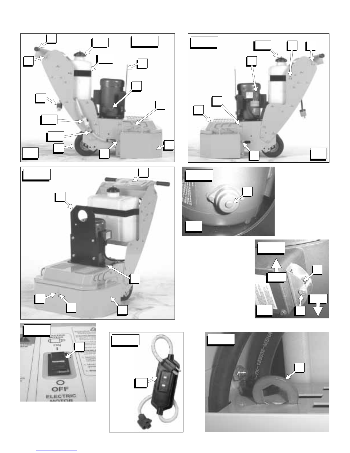
A. Front Shield [FIG. 1].
B. Front Shield Bolts [FIG. 1, FIG. 3].
C. Adjustable Handle [FIG. 1].
D. Handle Bolts [FIG. 1].
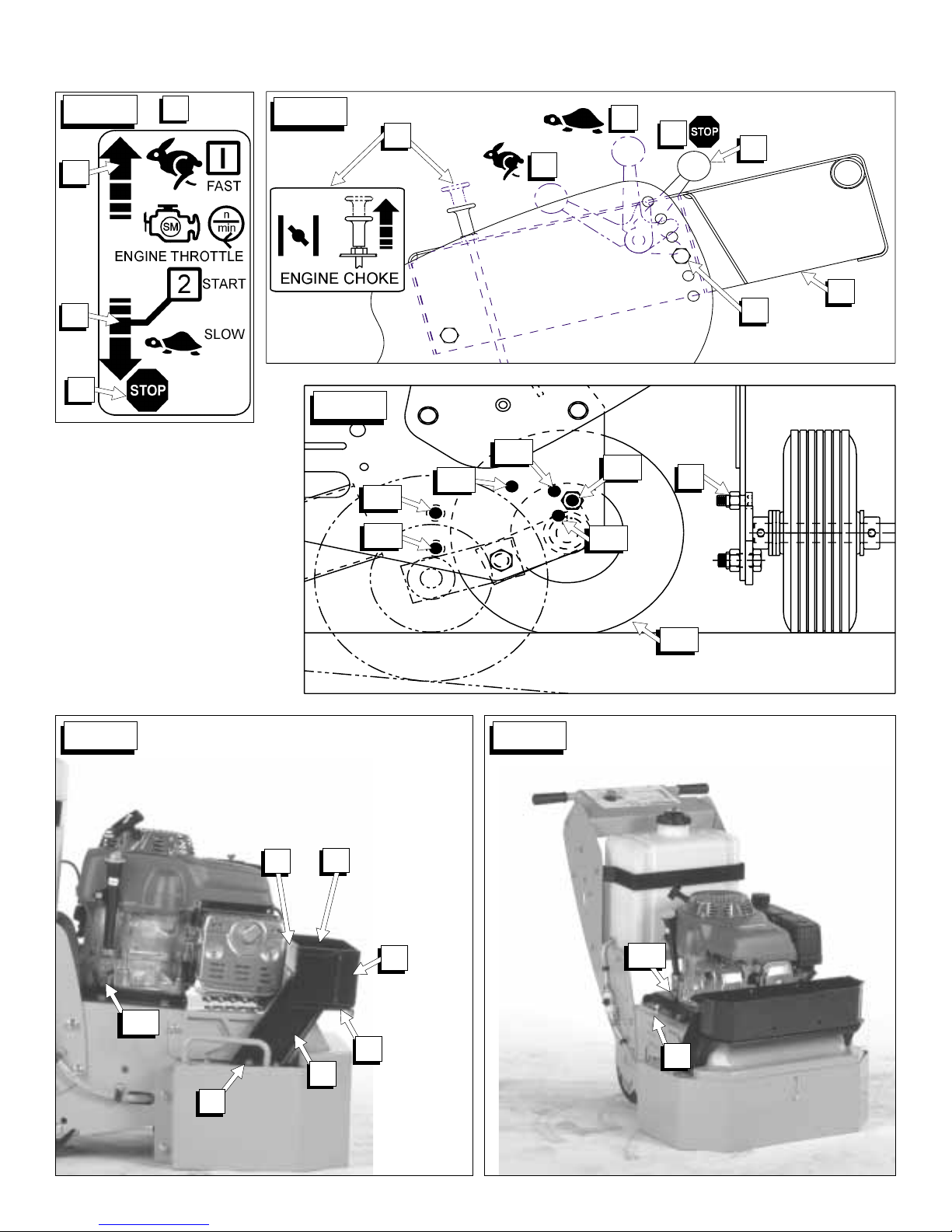
E. Axle In Transport Position [FIG. 11].
F. Axle In Operation Position [FIG. 11].
G. Axle Stop Bolt [FIG. 11, FIG. 30].
H. Electrical ON / OFF Switch (Electric Model Only)
[FIG. 6].
I. -----J. Voltage Change Switch (Electrical Model Only)
[FIG. 5].
K. Reset Button (Electrical Model Only) [FIG. 4].
L. Throttle Lever (Gasoline Model Only) [FIG. 10].
M. Engine STOP Position (Gasoline Model Only)
[FIG. 10].
N. Engine START Position (Gasoline Model Only)
[FIG. 10].
O. Engine Choke (Gasoline Model Only) [FIG. 10].
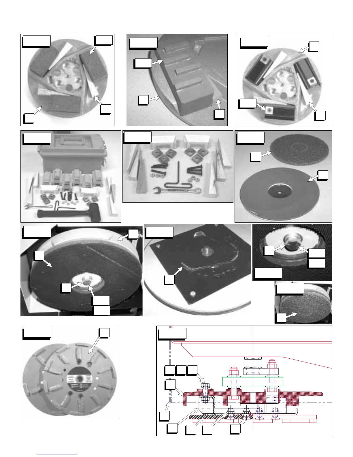
P. Accessory Disks [FIG. 20, FIG. 14, FIG. 15, FIG.
16].
Q. Multi-Segmented Diamond Disks [FIG. 24, FIG.
25].
R. Diamond Disk Adapter [FIG. 25].
S. Diamond Disk Attaching Hardware [FIG. 25].
S1. Flat Head Screws.
S2. Locknuts.
T. Diamond Disk Adapter Attaching Hardware [FIG.
25].
T1. Capscrew, 3/8-16UNC x 1-1/2” Long.
T2. Lockwasher 3/8”, Split Type.
T3. Washer, .3/8 SAE.
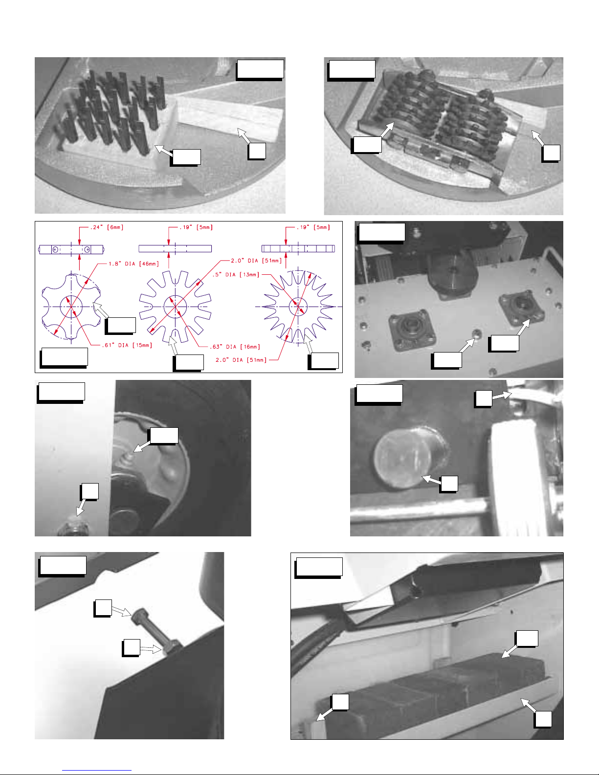
U. Wooden Wedges [FIG. 14, FIG. 15, FIG. 16].
V. Wrench, ½” (13 mm) x ¾” (19 mm) [FIG. 8]
V1. Wrench Can Be Used On Items Marked “V1”
[FIG 2, FIG. 3, FIG 20].
W. Lifting Eye (Electrical Model Only) [FIG. W].
X. Tool Storage Area: Holds 6 Extra 2 x 2 x 4” Tools
[GG], & 9 Extra Wooden Wedges [U]. [FIG. 33].
Y. Lifting Bail – Standard Equipment for Gas Model.
Z. Weight Tray (FIG. 12)
AA. Weight Tray Hardware – With Optional Weight Kit
[FIG. 12]
BB. Weight Box – With Optional Weight Kit [FIG. 12]
CC. Hold Down Bolts (Weight Box) [FIG. 12].
DD. Weight Bar [FIG. 12].
EE. Weight Bar Attaching Hardware [FIG. 12].
FF. Lifting Handles [FIG. 1].
GG. Tool (2 x 2 x 4” Type):
GG1. Grinding Block [FIG. 14].
GG2. Tungsten Carbide Segment Block [FIG. 16].
GG3. Diamond Blocks [FIG. 15].
GG4. Wire Brushes [FIG. 26].
GG5. Scarifier Wheels [FIG. 27].
GG5A. Star Wheel [FIG. 28].
GG5B. Beam Wheel [FIG. 28].
GG5C. Tungsten Carbide Wheel [FIG. 28].
HH. Tool Holding Pad [FIG. 19, FIG. 20, FIG. 21].
II. -----JJ. Scrubbing Pad [FIG. 19].
KK. -----LL. Electrical Plug [FIG. 1].
MM. Ground Fault Circuit Interrupter (GFCI) [FIG. 7].
NN. Engine “Fast” Speed (Gas Model Only) [FIG. 10].
OO. -----PP. Gearbox Cover [FIG. 2].
QQ. Water Tank Kit [FIG. 2].
QQ1. Tank with Lid [FIG. 1].
QQ2. Water Tank [FIG. 1].
QQ3. Water Tank Bracket [FIG. 1].
QQ4. Hose Clamps [FIG. 1].
RR. Lubrication Points:
RR1. Spindle Bearings [Six (6) Places] [FIG. 29].
RR2. Rear Wheels [FIG. 30].
RR3. Gearbox Grease Port [FIG. 29].
SS. Tool Holding Pad Attaching Hardware [FIG. 20,
FIG. 22, FIG. 25].
SS1. Capscrew, Hex Hd, .500-20UNC x 1.25”.
SS2. Lockwasher, .500”, Split Type.
TT. Voltage Change Lock Bolt [FIG. 5].
UU. Belt Tensioning Drawbolt [FIG. 32].
VV. Serial Number Plate [FIG. 13].
WW. Oil Drain Hose [FIG. 12, FIG. 13].
XX. Dust Port Cap [FIG. 31].
YY. Belt Tensioning Jam Nut [FIG. 32].
ZZ. Motor Platform Capscrews [FIG. 3].
AAA. Hose Port Cover [FIG. 31].
11

SAFETY WARNINGS FOR OPERATION OF THIS MACHINE
DO read this entire operator’s manual before operating this machine. Understand all warnings, instructions, and controls.
DO keep all guards in place and in good condition.
DO wear safety-approved hearing, eye, head and respiratory protection.
DO read and understand all warnings and instructions on the machine.
DO read and understand the symbol definitions contained in this manual.
DO keep all parts of your body away from the grinding disks and all other moving parts.
DO know how to stop the machine quickly in case of emergency.
DO shut off the engine and allow it to cool before refueling.
DO inspect the accessory disk, and tool adapters for damage before installing the tools.
DO use only tools manufactured for use on surface grinders.
DO verify grinder drive configuration by checking engine / motor RPM, and spindle shaft RPM, pulley diameters.
DO read all safety materials and instructions that accompany any tool used with this machine.
DO inspect each tool carefully before using it. If there are any signs of damage or unusual wear, DO NOT USE THE
TOOL!
DO mount the tool solidly and firmly.
DO make sure the tool and accessory disk are clean and free of dirt and debris before mounting the tool on the saw.
DO use the correct tool for the type of work being done. Check with tool manufacturer if you do not know if tool is correct.
DO operate this machine only in well ventilated areas.
DO instruct bystanders on where to stand while the machine is in operation.
DO establish a training program for all operators of this machine.
DO clear the work area of unnecessary people. Never allow anyone to stand in near the machine while the engine is
running.
DO always tie down the machine when transporting.
DO use caution and follow instructions when setting up or transporting the machine.
DO have all service performed by competent service personnel
DO verify that the tool size is compatible with the machine before mounting the tool.
DO make sure the fuel caps of the machine and the fuel can are properly tightened before starting the engine. Move fuel
can at least 10 feet from machine after fueling.
DO clean the machine after each day’s use.
DO remove adjusting tool and wrenches from machine before turning it on.
DO keep the handles dry, clean and free of oil and dirt.
DO carefully maintain and clean for better and safer performance. Follow instructions for changing accessories. Inspect
tool cords periodically and, if damaged, have repaired by authorized service facility.
DO use caution when handling fuel.
DO always give a copy of this manual to the equipment user. If you need extra copies, call TOLL FREE 1-800-288-5040.
DO Determine the nature and volatility of any material that will come in contact with the grinding action of the tools used by
this machine.
DO operate the machine only in areas where the material in contact with the grinding tools is known.
DO use only non-flammable and proper substances to improve the material removal from the work area.
12

DO NOT operate this machine unless you have read and understood this operator’s manual.
DO NOT operate this machine without all guards in place.
DO NOT leave this machine unattended while the engine or motor is running.
DO NOT work on this machine while the engine or motor is running.
DO NOT operate this machine when you are tired or fatigued.
DO NOT operate the machine if you are uncertain of how to run the machine.
DO NOT use damaged equipment or tool.
DO NOT touch or try to stop a moving tool with your hand.
DO NOT transport a machine with the tools mounted on the machine.
DO NOT use a tool that has been dropped or damaged
DO NOT touch the tools immediately after use. These tools require several minutes to cool after operation.
DO NOT use damaged or worn accessory disk.
DO NOT allow other persons to be near the machine when starting, refueling, or when the machine is in operation.
DO NOT operate this machine in an enclosed area unless it is properly vented.
DO NOT operate this machine in the vicinity of anything that is flammable. Sparks could cause a fire or an explosion.
DO NOT operate this machine while under the influence of drugs or alcohol.
DO NOT operate this machine with any of the guards removed.
DO NOT operate this machine unless you are specifically trained to do so.
DO NOT start operation of the machine until you have a clear work area and secure footing.
DO NOT use flammable substances, unsecured loads or people as extra weight. Injury to the operator or other persons
could result!
DO NOT use flammable, or improper substances to improve the material removal from the work area.
DO NOT operate the machine if unknown substances are on or near the work area.
DO NOT operate the machine before you determine the nature and volatility of any material that will come in contact with
the grinding tools used by this machine.
This machine was designed for certain applications only. DO NOT modify this machine or use for any application
other than for which is it was designed. If you have any questions relative to its application, DO NOT use the
machine until you have written Diamant Boart, Inc. and we have advised you.
*****************
Diamant Boart Inc.
17400 West 119th Street
Olathe, Kansas 66061, USA
13

FEATURE MODEL
Model Number:
Item Number:
Power Source:
Maximum Horsepower:
Motor / Engine Rated RPM:
Brand:
Model / Specification:
Voltage:
Phase:
Full Load Current @ 115V:
Full Load Current @ 230V:
Displacement:
Bore:
Stroke:
Cylinders:
Fuel Capacity:
Oil Capacity:
Air Filter:
Starter:
Coolant:
Spindle Shaft RPM:
Clutch Engagement RPM:
Nominal Weight:
Operating Weight
(With Tools, Fuel, Oil, Etc):
Grinding Width:
Gearbox Ratio:
Handle:
Dust Port:
Tires & Wheels:
Axle:
Tool Storage Area (See FIG. 33):
OPTIONS:
Water Tank Kit (P/N 177855):
Weight Kit (P/N 177856):
Lift Bail Kit (P/N 177901):
(For Gas/Electric Models)
Diamond Disk Adapter Kit
(P/N 177861):
FELKER® Surface Trac SPECIFICATIONS
ST15E ST11H
173366 173367
Electric Gasoline
1-1/2 (1,1 kw) 11 (8,2 kw)
1725 3600
Baldor Honda
TEFC GXV340
115 / 230 -----
Single -----
19 -----
9.5 -----
----- 20.6 cubic inches (338 cc)
----- 3.2 inch (82 mm)
----- 2.5 inch (64 mm)
----- 1
----- .61 US Gallon (2,3 Liter)
----- 1.16 US Quart (2.32 US Pints) (1,09 Liter)
----- Dual Element: Pleated Paper & Foam Pre Cleaner
Capacitor Recoil
Air Air
230 279 – 560 (Variable Speed Using Engine Throttle)
N/A 1800
309 Lb. (140 kg) 328 Lb. (149 kg)
320-350 Lb.
(145-159 kg)
22.2 inches (56,4 cm)
4.48 : 1
Six (6) Position Adjustment with Rubber Grips
3.0” (76,2 mm) Outside Diameter will accept 3” (76mm) Inside Dia. Flex Hose
8” Diameter, ¾” Bore, Semi-Pneumatic,
Steel Wheel with Roller Bearings & Grease Fitting
¾” Diameter, Zinc Plated with One Transport & Four (4) Operation Positions
Holds Six (6) Extra Tools (2 x 2 x4”) and Nine (9) Extra Wooden Wedges
Plastic, 7.5 Gallon (28.4 Liter), Quick-Connect ON/OFF Valve, Brass Fittings &
Spray Nozzle, Weight 6.5 Lbs. (2,9 kg) Less Water
Includes Weight Tray, Removable Weight Box, & 58 Lbs. (26 kg) of Steel
Weights. Can Hold an additional Nine (9) Weight bars (Sold Separately)
[58 Lbs (26 kg)] for a Total Maximum Weight of 117 Lbs. (53 kg)
One Point Lifting, 7 Ga. x 1.5” (38 mm) Steel, Weight 14 Lbs. (6,3 kg)
Gas Model: Standard Equipment Beginning Spring 2000.
Electric Model: Has Lifting Eye (Standard Equipment), but this Kit Will Fit.
Attaches Two (2) 10” (254mm) Diameter Diamond Disks To the Machine. Kit
Includes adapter disks and all attaching hardware. Diamond Disks must be
purchased separately.
340-370 Lb.
(154-168 kg)
14
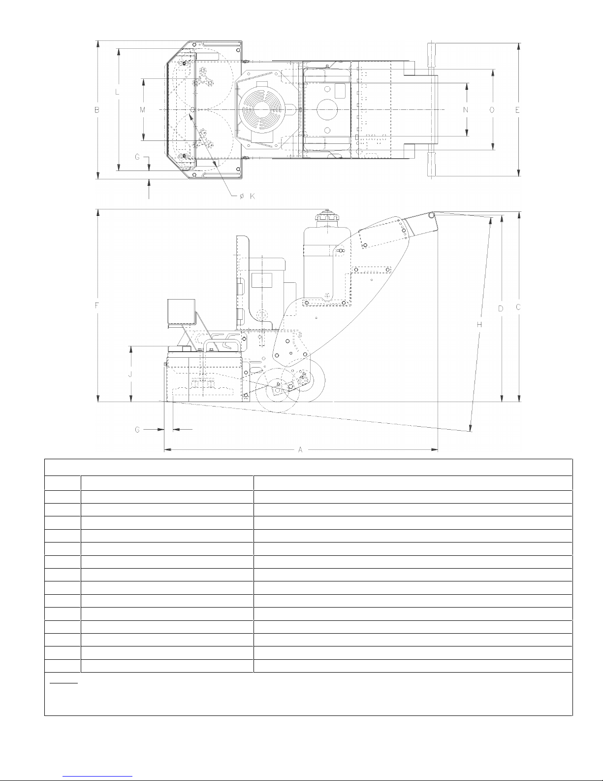
Dimensions (Note 1)
Item Length (cm) Description
A 50.2” (127.5) Length – Maximum (With Handle In Low Position)
B 25.12” (63.8) Width
C 37.6” (95.5) Operating Height (Maximum – Note 1)
D 37.0” (94.0) – 31.5” (80.0) Handle Height (Maximum – Minimum)
E 24.2” (61.5) Handle Width
F 35.0” (88.9) Water Tank Height
G1.50” (3.8) Grind To Wall (Front and Side)
H 41.9 (106.5) Transport Height (Maximum – Note 2)
J 10.2” (25.8) Front Height
K 11.0” (27.9) Disk Diamet er
L 22.2 (56.4) Grinding Width
M 11.200 (28.45) Spindle Center Distance
N9.6” (24.4) Width Inside Tires
O 14.6” (37.0) Width Outside Tires
Notes:
1. Dimensions are for the machine with the axle in “operation” position unless otherwise specified.
2. Dimension “H” is for the machine with the axle in “Transport” position.
15
(DT15_dims.tif)

Tool
Grinding Stones
(See FIG. 14)
See Current
Product Catalog for
Part Numbers of
these Items.
Diamond
Segment Blocks
(See FIG. 15)
See Current
Product Catalog for
Part Numbers of
these Items.
Tungsten
Carbide Blocks
(FIG. 16, FIG. 17,
FIG. 18)
Scarifier Wheels
(FIG. 27, FIG. 28)
See Current
Product Catalog for
Part Numbers of
these Items.
Wire Brushes
(FIG. 26)
Diamond Disks
(FIG. 25)
See Current
Product Catalog for
Part Numbers of
these Items.
Scrubbing Pads
(FIG. 19)
Tool Application Guide
Attachment To
Machine Task
Accessory Disk and
Wooden Wedges
(Section 4.1)
Accessory Disk and
Wooden Wedges
(Section 4.2)
Accessory Disk and
Wooden Wedges
(Section 4.3)
Accessory Disk and
Wooden Wedges
(Section 4.4)
Accessory Disk and
Wooden Wedges
(Section 4.5)
Adapter Plates
(Section 4.6)
Tool Holder Pad
(Section 4.7)
Available In Different Silicon Carbide “Grit” Sizes, such as:
TC-10 Coarse Grit: Maximum material removal, General grinding &
removal of trowel marks, high spots, and rough sections of concrete. Life
TC-24 Medium Grit: Lower material removal rate, Finer fini sh grinding of
concrete, and rough grinding of Terrazzo and other s t one type. Life 6 – 10
TC-80 Fine Grit: Still lower material removal rates. For polishing of
concrete and medium gri ndi ng on Terrazzo and stone type floors. Life 8 –
(The larger the number, the finer the grai n structure, and the smoother the
surface material f i ni sh, and the longer the grinding stone life)
Remove High Spots, Trowel & Rain Marks , Paints, Sealers & Mastic s,
Uneven Joints, Aggressi ve Grinding of Large Rough Areas, Removal of
epoxies, paints and many thin fi l m coatings, or Final Preparation for new
GB-10 General Purpose, GB-20 Abrasive Materi al s
Removal Rates: Up to five (5) times the material removal rate of Coarse
Removal of Thick Paint Coatings, Not Recommended f or Thi n (< 5 mil)
Films of Materials. Not Recommended for adhesive, rubber deposits and
mastics which have a t endency to extrude or smear rather than “shear”
loose from the floor s urf ace – however water or a water / sand mixture can
be added on the surface to reduce this problem.
Remove Fiberglass, Ice, Oil-Dry, Foam-Fill Packing Material & Floor
Star Wheel: Hardened Carbon Steel material. For removal of thin c oatings
and encrusted accumul at i ons of material. Cleaning concret e of asphalt
surfaces. Removing thick build-up of grease, paint, and s ome resins.
Light scarifying before applic ation of coatings or sealer. Creates a s wept,
Beam Wheel: Medium duty, for concrete and asphalt scari fying. De-
scaling steel decks. Removing thick material build-up of grease, paint, and
some resins. Twice the l i f e, near the same cost as a star wheel.
Tungsten Carbide Wheel: Heavy Duty asphalt or concrete scarifying, or
de-scaling of steel decks. 10 times the life of a star wheel.
Notes: Should be rotated end for end i n accessory disk every hour to avoid
the wire taking a set (flat wire will bend in one direction). External weight
added to machine will NOT normally increase production rates , but only
Remove High Spots, Trowel & Rain Marks , Paints, Sealers & Mastic s,
Uneven Joints, Aggressi ve Grinding of Large Rough Areas, Removal of
epoxies, paints and many thin fi l m coatings, or Final Preparation for new
Available In Different “Grit” Sizes and 10 or 20 Diamond Segments (per
TDGH-20A for Asphalt or Abrasive Surfaces (20 Segments)
Removal Rates: Up to five (5) times the material removal rate of Grinding
Remove mildew, rust, or di scoloration from concrete, clean concrete forms,
strip scale and rust f rom steel plate surfaces, remove fins or marks on
Light Grinding of Rough Areas
Available In Different “Grit” Sizes:
GB-30 Epoxy & Non-Abrasive Materials.
Life: Up to 15 times the life of Grinding Stones.
Buildups. Lightly Texture Surface.
or “broomed” type of finish.
Light Scarifying & cl eani ng.
accelerate the wire brush wear rates.
TDGH-10C for Cured Concrete (10 Segments)
TDGH-20C for Cured Concrete (20 Segments)
Life: Up to 15 times the life of Grinding Stones.
underlayment material s.
4-10 hours.
hours.
20 hours.
coating.
Grinding Stones.
coating.
disk):
Stones.
Surface Material
Concrete
Terrazzo
Other Stone Types
Concrete
Terrazzo
Other Stone Types
Concrete, Epoxy,
Coatings, & Mastics
Concrete, and Tile
Concrete, Asphalt,
Steel, and Tile
Concrete
Terrazzo
Other Stone Types
Concrete, Steel
16

PRE-OPERATION CHECKLIST
Before leaving our factory, every machine is thoroughly tested. Follow our instructions strictly
and your machine will give you long service in normal operating conditions.
Before starting the machine, make sure that you read this entire Operations Manual and are
familiar with the operation of the machine.
WITH MACHINE COLD AND SETTING LEVEL:
Gasoline Models: Check engine oil. Fill to the full mark on dipstick with 10W30 oil, class MS, SD, SE or better.
Electric Models: Verify that all electrical connections are intact.
1-2 HOUR OPERATION CHECK LIST:
ALWAYS place the machine on a level surface with the engine / motor “OFF”, the ignition switch
set in the “OFF” position and disconnected from the power source before performing any
maintenance. Let the machine cool down!!
1. Check the engine air cleaner hose clamps. Tighten as required.
2. Tension the drive V-belts. DO NOT over tension!
SCHEDULED MAINTENANCE QUICK REFERENCE
Before performing any maintenance, ALWAYS place the machine on a level surface with the
engine / motor “OFF”, the ignition switch set in the “OFF” position and disconnected from the
power source!
SERVICE DAILY:
1. Check engine oil level.
2. Check all guards for damage.
3. Check hoses and clamps for damage or looseness. Tighten or replace as
necessary.
4. Check air cleaner. Clean or replace as required.
5. Clean the machine at the end of the day.
SERVICE EVERY 50 HOURS:
1. Replace engine oil and oil filter.
2. Clean engine air fins.
3. Check V-belt tension. DO NOT over tension!
4. Clean Engine fuel bowl.
17

• Mandatory
• Obligatorio
• Prohibition
• Prohibición
Before starting up machine make sure you
read these instructions and are familiar
with the operation of this machine.
• Indication
• Indicación
• Warning Triangle
• Triángwulo De
Advertencia
These signs will give advice for your safety
Before leaving our factory every machine
is thoroughly tested.
Follow our instructions strictly and your machine
will give you long service in normal operating
conditions.
1. Features
Use: Surface grinding of concrete or other types of
flooring. For repairing horizontal surfaces that
have been damaged by the weather, or by
improper finishing methods, or that require
removal of deteriorated coatings, overlays, or
buildups.
Tools:
1) 2 x 2 x 4” (50 x 50 x 100 mm) size, Six (6) per unit.
In any of the types shown below:
a) Grinding Stones [FIG. 14]
b) Tungsten Carbide Segment Block [FIG.
16].
c) Tungsten Carbide Impregnated Grinding
Block (Not Shown)
d) Scarifier Blocks (Star, Beam, TC wheels)
[FIG. 27 & FIG. 28].
e) Wire Brushes [FIG. 26].
f) Diamond Blocks [FIG. 15].
2) Multi-Segmented Diamond Disks: Two (2) disks per
unit, 10” (250 mm) diameter, 10 or 20 diamond
segments on each disk [FIG. 24 & FIG. 25].
3) Tool Holding Pad, with “hook-and-loop” type of tool
attachment, holds the following [FIG. 19]:
a) Scrubbing Pad [JJ] [FIG. 19]: Two (2) pads
per unit, 10” (250 mm) diameter, Nylon
mesh Impregnated with Silicon Carbide.
(For information contact your Dealer)
Depth of Cut (Maximum):
See Section 4 (Tool Installation & Application)
Maximum material Size: N/A
Nominal & Operating Weight: See “Specifications”.
Dimensions, Grinding Width, Spindle Shaft RPM:
See “Saw Dimensions”.
The working area must be completely clear,
well lit and all safety hazards removed (no
water or dangerous objects in the vi cinity)
The operator must wear
protective clothing
appropriate to the work he
is doing.
We recommend hearing,
respiratory and eye
protection.
Any persons not involved in the work,
should leave the area.
Only work of flat horizontal areas.
Working on steep slopes or hills could
cause the operator to lose control of the
machine. This could result in injury or
death to the operator or other persons in
or near the work area!
2. Assembly
q
When unpacked, this unit is fully assembled,
except for installation of the grinding “tools”. For
tool installation See Section 4 of this document.
q
The dealer or end user must do the installation of
optional or accessory items, such as a water tank
kit.
3. Check Before Operating
All Models:
q
Take into account the working conditions from a
health and safety point of view.
q
For start up refer to the engine, or motor manual.
18

Electric Models:
The applicable national and local electrical
codes and enforcement bodies will be the
determining authority on the proper
connections and use of this machine. In all
cases it the operator/owner’s responsibility to
ensure that this equipment is in full
compliance with these codes.
All machine adjustments & maintenance shall
only be done after the machine’s power switch
has been put in the “OFF” position & the
power supply cord completely disconnected.
q
Make sure that the extension cord length is
properly sized for the motor used on this saw. See
the chart in Section 2 of this document.
q
Single phase 1-1/2 hp motors are factory wired for
115 volt service and furnished with the correct
NEMA configuration Plug (LL) [See FIG. 1] on the
motor pigtail. See Table 1 below for the proper
matching connectors:
Table 1
Electric Motor Plugs & Connectors
Motor Pigtail
Motor Wired For
Voltage
1-1/2 HP
1-1/2 HP
q
For operator convenience, the 1-1/2 hp motor has
115 V L5-20P L5-20R
230 V L6-15P L6-15R
Plug
(NEMA No.)
a Voltage Change Switch (J) [See FIG. 5] that
allows operation on a 115 VAC or a 230 VAC
power source. The voltage change switch (J) is
mounted on the terminal box of the motor and must
be set to either 115, or 230 Volt, to match the
voltage supply. Make sure that the Voltage Change
Lock Bolt (TT) is in position. It will prevent the
Voltage Change Switch [See FIG. 5] from being
accidentally moved into the wrong position.
WARNING: The Voltage Change Switch (J)
position is never to be changed while the motor
is running. Make sure that the Voltage Change
Lock Bolt (TT) is in position. It will prevent the
Voltage Change Switch from being accidentally
moved into the wrong position.
q
Local electrical codes may require changing the
plug on the motor to the proper NEMA connector to
match the voltage supply.
q
The operator must use plug and receptacle
connectors on all power cords (machine and
extension), designed and approved for the selected
motor voltage and equal to or greater than the
rated motor full load current.
q
The service receptacle, branch circuit conductors,
and overcurrent protection shall have an ampere
rating equal to or greater than the motor full load
current. According to the National Electrical Code
if the branch circuit has two or more receptacles,
Connector
Required
(NEMA No.)
each receptacle has a maximum load ampere
rating equal to 80% of the receptacle’s rating.
When this machine is set up to operate on 115
VAC, the motor has a full load rating of 19
amperes. This means that when operating this
machine on 115VAC, it can only be used on a
branch circuit with ONE 20-ampere rated
receptacle. If the circuit has two or more 20-
ampere receptacles, they each have load rating of
16 amperes and cannot be used by this machine.
WARNING: Always make sure the unit in
connected to a properly grounded electrical
outlet. Failure to comply with this warning
could result in serious bodily injury or death!
WARNING: DO NOT operate on low voltage!
Low voltage causes loss of power, motor
overheating, and possibly motor winding
burnout. Voltage should be checked at the
motor while it is operating.
q
The extension cord(s) used must have a voltage
rating greater than the selected voltage (115 or
230) and be sized for the rated motor full load
amps (as marked on motor specification plate).
q
Good motor performance depends on proper
voltage. Extension cords that are too long and / or
too small reduce the voltage to a motor under load.
Operating below this minimum voltage will cause
an increase in motor current resulting in slow
startup, and overheating in the motor and controls.
Sustained operation under these conditions will
result in permanent damage to the motor and
controls.
q
Long extension cords will probably have to be
oversized to minimize the voltage drop to the
machine. The size of the extension cord is
dependent on the total conductor length (all
extension cords) & the quality of the power source.
The power cord size shall be capable of supplying
a minimum of 90% of the motor nameplate
voltage at the motor, when the motor is running
rated full load.
q
Make sure that the extension cord length is
properly sized for the motor used on this machine.
Use extension cords NO SMALLER than the sizes
indicated in Table 2 below:
Table 2
EXTENSION CORD SIZE (Minim um)
MOTOR
HP 120 V 230 V 120 V 230 V 120 V 230 V
1-1/2 # 12 # 14 # 10 # 14 # 8 # 14
q
The branch circuit must have overcurrent
19
50 ft Long 75 ft Long 100 ft Long
protection in the form of a circuit breaker or fuses.
The purpose of the overcurrent protection is to limit
the current in the branch circuit conductors and
connections to an amount equal to or less than
their ratings. This is to prevent overheating that
can lead to damage or a fire. The overcurrent

protection will not protect the operator from an
electrical shock due to improper grounding
practice, frayed or cracked extension cords, or
other defective electrical components. This
exposure to electrical shock increases greatly
whenever the equipment is used around water or
other conductive fluids. The operator will be
provided with electrical shock protection whenever
the machine is connected to a circuit that has a
Ground Fault Circuit Breaker. The Ground Fault
Circuit Breaker will open the circuit whenever it
senses a fault current, greater than a few
milliamps, in the ground path. If a receptacle with a
Ground Fault Circuit Breaker is not available, a
Portable Ground Fault Circuit Interrupter [MM] [See
FIG. 7] can be used at the branch receptacle to
provide the same level of protection.
Gasoline Model:
q
Engine Fuel: Check the engine operation manual.
Unleaded gasoline is recommended.
q
Engine Oil: Put the AXLE in the OPERATION
POSITION [F] [See FIG. 11] so that the engine is in
a horizontal position, then, check that the engine oil
level is correct. Check the oil level frequently to
ensure that the level never falls below that
specified in the engine operation manual. If the oil
level is low, add SAE 10W30, service classification
SF or SG oil (for normal conditions) as
recommended in the engine operation manual. DO
NOT overfill engine with oil!
q
Before starting the engine verify that the Throttle
Lever [L] is between the START [N] and STOP [M]
position. This will allow the engine to be started
while the clutch is disengaged. NOTE: The engine
clutch will engage at 1800 RPM, and the Accessory
Disks [P] will begin to rotate.
q
Before starting the engine, verify that the engine
does NOT exceed 20 degrees angle of inclination
when the unit is in operation.
WARNING: Run the machine only if the
grinding heads are on the ground. Raising the
front of the machine with the engine or motor
running could cause injury or death to bystanders or the operator. Also, engine
inclination angles greater than 20 degrees
could cause severe engine damage and void
your engine warranty!
4. Tool Installation
TOOL INSTALLATION:
1) Rear Axle Position (See FIG. 11): Make sure the
Axle is in the Transport Position [E]. Using TABLE
3 (below) install the Axle Stop Bolts [G] in the
proper position for the tool being mounted. The
Axle Stop Bolts [G] are factory installed in the F2
position.
Table 3 shows the tools specified by our
company. Tools from other manufactures
may fit onto this machine. Measure “Tool
Height” to determine the proper axle position
(See TABLE 4) for these tools.
TABLE 3
Rear Axle Positions (See FIG. 11)
Tool Tool Height Axle Position
Grinding Stones 2.0” (51 mm)
Tungsten Carbide
2.1” (53 mm)
Block
Diamond Segment
2.1” (53 mm)
Block
Star wheels
Beam Cutter Wheels
TC Wheels
2.25” (57 mm)
2.25” (57 mm)
2.15” (54 mm)
Diamond Disks 2” (51 mm)
Scrubbing Pad
(with Adapter)
1.7”
(43.2mm)
If the tool to be installed is not listed in TABLE 3:
a) Measure the “Tool Height”.
TABLE 4
Tool Height for Axle Positions (See FIG. 1)
Axle Position Minimum Tool Height
F1 2.44” (62 mm)
F2 2.00” (50.8 mm)
F3 1.69” (42.9 mm)
F4 1.00” (25.4 mm)
b) Using TABLE 4, find a “Minimum Tool Height”
equal to, or greater than, the measured tool height.
c) Referencing FIG. 11, install and tighten the Axle
Stop Bolts [G] in the Axle Position (F1, F2, etc)
determined from step b) above.
2) Raise Front Shield (A): Loosen the three (3)
Capscrews [B] that hold the Front Shield [A] in
position. Raise the Front Shield to its upper
position, then tighten the Capscrews [B] to hold it in
place.
3) Tilt Machine Backwards: When on a flat surface,
tilt the machine backward until the Handles [FF]
rest on the ground. If you are not sure the machine
will stay in this position, add a weight or other
device to the handle to secure them to the ground.
WARNING: Make sure the machine is stable
when the front end is raised into the air!
Secure the machine in this position if you are
not sure about its stability. Secure machine
BEFORE starting attachment of the tools to
the accessory disks!
4) Tool Installation on Accessory Disk [P]:
See FIG. 14, FIG. 15, FIG. 16, FIG. 26, FIG. 27
a) Place the Tool [GG 1] so that it rests against the
back and outside of the tool holding area of the
20
F2
F2
F2
F2
F2
F2
F2 or E2
F3

Accessory Disk [P]. Place the Wooden Wedge [U]
between to the inside edge of the Tool [GG 1] and
the Accessory Disk [P].
b) Firmly tap the Wooden Wedge [U] into position
using a hammer. Tap the Wooden Wedge [U] until
the Tool [GG 1] is securely fastened into the
Accessory Disk [P]. Rotate the Accessory Disk [P]
and repeat this procedure for all six (6) tools.
⇒ Note: Soaking the Wooden Wedges (U) in water
before assembly could increase the gripping power
of the wedges and prolong the time that the tool
stays fixed to the machine.
c) Gently lower the front of the machine until the tools
touch the ground.
d) Pivot the axle so that it is in the OPERATION
POSITION [F] [FIG. 2].
e) Lower the FRONT SHIELD [A] from its upper
position. Loosen the three (3) CAPSCREWS [B]
and lower the shield so that it is only 3/8-1/2” (1012 mm) from the ground.
4.1
For Light Grinding of Rough Areas. Material is Silicon
Carbide, the “grit” size is designated by number (similar
to most abrasive products). The larger the number, the
finer the grain structure, the smoother the surface finish
achieved, and the longer the grinding stone life. Some
of the available “Grit” Sizes are shown below:
4.2
Remove High Spots, Trowel & Rain Marks, Paints,
Sealers & Mastics, Uneven Joints, Aggressive Grinding
of Large Rough Areas, Removal of epoxies, paints and
many thin film coatings, or Final Preparation for new
coating.
Available In Different “Grit” Sizes:
Removal Rates: Up to five (5) times the material
removal rate of Coarse Grinding Stones.
Life: Up to 15 times the life of Grinding Stones.
Grinding Stones [See FIG. 14]
a) TC-10 Coarse Grit: Maximum material
removal, General grinding & removal of
trowel marks, high spots, and rough
sections of concrete. Life 4-10 hours.
b) TC-24 Medium Grit: Lower material
removal rate, Finer finish grinding of
concrete, and rough grinding of Terrazzo
and other stone type. Life 6 – 10 hours.
c) TC-80 Fine Grit: Still lower material
removal rates. For polishing of concrete
and medium grinding on Terrazzo and
stone type floors. Life 8 – 20 hours.
Diamond Segment Blocks [FIG. 15]
GB-10 General Purpose
GB-20 Abrasive Materials
GB-30 Epoxy & Non-Abrasive Materials.
4.3
that includes six steel blocks, six tungsten carbide
cutters, hardware and tools, and six wooden wedges.
also available. It includes six tungsten carbide cutters,
six wooden wedges, and all hardware and tools to
mount the cutters.
and works best at removal of thick coatings such as
paint buildups. Not recommended for thin (< 5 mil)
films of materials. Not recommended for adhesives,
rubber deposits and mastics that have a tendency to
extrude or smear rather than “shear” loose from the
floor surface. A water or a water / sand mixture can be
added on the surface to reduce this problem
additional external weight to the machine can also
improve the material removal rate.
Each insert has eight (8) cutting edges. When one of
the edges becomes dull, loosen the attaching bolt
using the hex wrench provided, and rotate the insert 90
degrees. When these four (4) cutting edges are dull,
simply remove the insert and flip it over to expose four
(4) new cutting edges.
4.4
Remove Fiberglass, Ice, Oil-Dry, Foam-Fill Packing
Material & Floor Buildups. Lightly Textures Surface.
Tungsten Carbide Blocks [See FIG. 16]
Comes in a complete kit (P/N 177823) [FIG. 17]
A replacement cutter kit (P/N 177824) [FIG. 18] is
Removes material with a cutting or shaving action
. Adding
Each tool contains one tungsten carbide insert.
Scarifier Wheels [FIG. 27, FIG. 28]
Available in three (3) configurations:
a) Star Wheel: Hardened Carbon Steel
material. For removal of thin coatings and
encrusted accumulations of material.
Cleaning concrete of asphalt surfaces.
Removing thick build-up of grease, paint,
and some resins. Light scarifying before
application of coatings or sealer. Creates
a swept, or “broomed” type of finish.
b) Beam Wheel: Medium duty, for concrete
and asphalt scarifying. De-scaling steel
decks. Removing thick material build-up of
grease, paint, and some resins. Twice the
life, near the same cost as a star wheel.
c) Tungsten Carbide Wheel: Heavy Duty
asphalt or concrete scarifying, or descaling of steel decks. 10 times the life of
a star wheel.
Assembly: When new cutters are installed, be sure
to “stagger” the washers in order in avoid any “blind
spots” in the cutter path (On any one cutter block
put the first washer on the opposite end of each
stack of cutters). Also make sure that the wheels
can rotate freely when the attaching Capscrews are
tightened.
Bushings: Be sure to inspect the cutter bushings on
a regular basis. Worn bushing can cause the
21

Scarifier Wheels to break and be thrown against
the inside of the machine frame.
4.5
For Light Scarifying and cleaning. Flat wires are
available in many sizes and configurations. They
should be rotated end-for-end in the Accessory Disk [P]
every hour to avoid the wire taking a “set” (wire will
bend in one direction). External weight added to
machine will NOT normally increase production rates,
but only accelerate the wire brush wear rates
4.6
a) Temporary removal of the Front Shield (A) may be
b) Attach the Multi-Segmented Diamond Disks (Q) to
c) Attach the Diamond Disk / Adapter Plate Assembly
d) Gently lower the front of the machine until the tools
e) Pivot the axle so that it is in the Operation Position
f) Lower the Front Shield [A] from its upper position.
Notes: If machine starts to vibrate and shake try
removing external weight from the machine. If the
vibration continues, move the axle into the “E2” position
[See FIG. 11]. This position is normally a “transport”
position, but for the diamond disks it removes most of
the weight from the front of the machine and allows the
disks to glide over the surface rather than dig into the
surface.
4.7
This machine will allow the use of Scrubbing Pads [JJ]
that are available from another manufacture.
Wire Brushes [See FIG. 26]
.
Multi-Segmented Diamond Disks [Q]
[See FIG. 24 & FIG. 25]
required to complete this installation.
the Adapter Plate (R) using the four (4) Flat Head
Screws (S1) and Thin Locknuts (S2) provided in
the Adapter Plate Kit (Kit Part Number 177861).
Tighten the Screws (S1) securely. Repeat this
procedure for the other Adapter Plate (R).
to the machine using the three (3) Capscrews (T1),
Lockwashers (T2), and Washers (T3) provided in
the Adapter Plate Kit. Tighten the Capscrews (T1)
securely. Repeat this procedure for the other
assembly.
touch the ground.
[F] [See FIG. 11].
Loosen the three (3) capscrews and lower the
shield so that it is only 3/8-1/2” (10-12 mm) from
the ground.
Tool Holding Pad (HH) Installation
[See FIG. 19, FIG. 20, FIG. 21, FIG. 22, FIG. 23]
a) Position the triangular area of the Tool Holding
Pad [HH] [See FIG. 21] so that it mates with
the triangular area on the Accessory Disk [P].
b) Use the 1/2-20UNF x 1-1/4” Long Capscrew
[SS1] and Lockwasher [SS2] to attach the Tool
Holding Pad to the Accessory Disk. Tighten
the capscrew securely, using the ¾” (19 mm)
End of the Wrench [V] [Shown in FIG.8].
c) Repeat this procedure on the other Accessory
Disk [P].
d) Install the Scrubbing Pads [JJ], two (2) per
machine. Gently press the tool onto the hook
and loop fastening system until it is secure.
e) Gently lower the front of the machine until the
tools touch the ground.
f) Pivot the axle so that it is in the Operation
Position [F] [See FIG. 11].
g) Lower the Front Shield [A] from its upper
position. Loosen the three (3) capscrews [See
FIG. 2 & FIG. 3] and lower the shield so that it
is only 3/8-1/2” (10-12 mm) from the ground,
then re-tighten the three (3) capscrews.
5. Operating Instructions
All Models:
q
Configure the unit with the proper tool for the job.
See Section 4 of this document for tool installation.
Start / Stop of Electric Models:
WARNING: Make sure the Voltage Change
Switch (J) [See FIG. 5], is set to either 115, or
230 Volt, to match the voltage supply. The
Voltage Change Switch (J) position is never to
be changed while the motor is running.
Make sure that the Voltage Change Lock Bolt
(TT) is in position. It will prevent the Voltage
Change Switch from being accidentally moved
into the wrong position.
Local electrical codes may require changing
the Plug (LL) [See FIG. 1] on the motor to the
proper NEMA connector to match the voltage
supply.
WARNING: Always make sure the unit is
connected to a properly grounded electrical
outlet. Failure to comply with this warning
could result in serious bodily injury or death!
1) Before starting the electric motor (if set for 115 Volt
Operation) push down on the handles just enough
to release pressure from the grinding disks. Start
the electric motor by turning the Power Switch [H]
(See FIG. 6) to the ON position.
WARNING: DO NOT push down on the
handles enough to lift the grinding disks from
the ground.
2) Once the motor has reached full speed, reduce the
downward pressure applied to the handles and let
the weight of the machine rest on the ground.
3) Hold the handles firmly and gently guide the
machine over the work area.
22

WARNING: Keep hands clear of rotating tools
during operation. READ ALL SAFETY
WARINGS before operating this machine.
4) STOPPING THE UNIT (Electric Models):
Stop the unit by turning the POWER SWITCH
[H] to the OFF position (See FIG. 6). Wait for
all tool movement to stop before transporting
the machine.
Start / Stop of Gasoline Models:
[FIG. 9 & FIG. 10]
1) Start the engine by using the procedure in the
engine operation manual.
2) Push Throttle Lever [L] up to, but not past, the
START position (Position “2”) [FIG. 9 & FIG. 10].
In this position the engine clutch will be disengaged
when the engine starts, so the accessory disks will
not rotate.
3) Starting a cold engine: Pull the Choke Lever [O]
upward. Pull the engine starter rope until the
engine starts, then push Choke Lever [O]
downward.
Starting a warm engine: Same as above, except
that Choke may not be needed. (Choke Lever [O]
may need to be pushed downward into “No Choke”
Position).
4) Move the Throttle Lever [L] past the START
position (Position 2) so that the engine clutch
engages and the accessory disks begin to rotate.
5) Hold the handles firmly and gently guide the
machine over the work area. Note: For rough
surfaces the engine speed (engine RPM’s) should
remain as low as possible. As soon as the surface
begins to become smooth the engine speed can be
increased, but running the engine at full throttle is
normally not required.
WARNING: Keep hands clear of rotating tools
during operation. READ ALL SAFETY
WARINGS before operating this machine.
6) STOPPING THE UNIT (Gasoline Models):
Normal or Emergency Stop: Pull the Engine
Throttle into the STOP position [Position M]
[See FIG. 9, and FIG. 10]. Wait for all tool
movement to stop before transporting the
machine.
6. Incidents During Operation
WARNING: Before inspecting or performing
any maintenance, ALWAYS locate the
machine on a level surface with the engine /
motor OFF, and the start switch in the OFF
position, and the power source disconnected.
1) If the engine or motor stops during operation,
check the following:
Electric Model:
a) Interruption to electrical connection: Check all
electrical connections.
b) Manual Overload switch has been tripped:
Single phase, 60 Hertz motors are equipped
with a manual overload Reset Button [K] [FIG.
4]. If the motor stops because of an electrical
overload and the overload Reset Button [K]
trips, turn the motor Power Switch (H) to the
OFF position [FIG. 6[. Allow the motor to cool
for 5 to 10 minutes, then push the Reset Button
[K]. A “click” sound indicates that the motor is
reset and ready for operation. Restart the
motor by reconnecting the machine to the
power source, and then turn the Power Switch
[H] to the ON position.
Gasoline Model:
a) Out of fuel: Check fuel level.
b) Low Oil Level: This unit is equipped with a shut
down system that stops the engine if a low oil
level is encountered. Check the engine oil
level with the rear axle in the Operation
2) Engine or Motor runs, but Accessory Disks don’t
Position [F].
All Models:
a) Excessively fast grinding could stall the engine
or motor.
rotate. Check the following:
All Models:
a) Check that the drive belt tension is adequate.
Gasoline Models:
a) Engine Clutch not properly working. Repair or
replace as required.
7. Maintenance
WARNING: Before performing any
maintenance, ALWAYS locate the machine on
a level surface with the engine / motor OFF,
and the start switch in the OFF position, and
the power source disconnected.
Check Daily:
1) All Models:
a) At the end of each day clean the machine to
2) Gasoline Model:
remove sludge buildup.
a) Check engine air cleaner daily! If cutting
dry check engine air cleaner every four
hours! Clean or replace air cleaner
element as recommended by the engine
manufacturer.
b) Check engine oil daily. Change engine oil
after every 50 hours of operation. Engine
Oil capacity is See engine operation
manual for proper care and maintenance.
23

Every 50 Hours:
1) All Models:
a) Lubrication Points:
Lubricate every 50 hours using only a
Premium Lithium 12 based grease
conforming to NLG1 GRADE #2
consistency.
1) Spindle Bearings: Six places total, three
Bearings [RR 1] on top of the gearbox
[FIG. 29] and three below the gearbox (Not
Shown).
2) Rear Wheels: Two places [FIG. 30].
2) Gasoline Model:
Change Engine Oil: Change engine
oil after every 50 hours of operation.
Engine Oil Type
Under normal operating conditions use SAE 10W30
API service classification SF or SG. See engine
operation manual for other recommended oil types.
Engine Oil Capacity (Honda GXV340)
1.16 U.S. Quarts 1.1 Liters
a) Engine Oil Change Procedure:
1. Drain the oil while the engine is still warm to
assure rapid and complete oil drain. Pivot the
Rear Axle To The Operation Position [F].
Place a bucket under the Oil Drain Hose [WW],
[FIG. 12, FIG. 13] to catch the used oil.
Remove the oil drain plug on the end of the Oil
Drain Hose [WW] and wait for all of the used oil
to be drained for the engine.
2. Re-install and securely tighten the plug in the
end of the Oil Drain Hose [WW].
3. Re-fill engine with the recommended oil type.
See the engine operation manual for the oil fill
location and proper oil level. Note that the
required oil capacity will be slightly larger
because of the volume of oil contained in the
Oil Drain Hose [WW].
4. Check the oil level. If the proper oil level is
indicated, re-install the oil fill cap.
5. Dispose of the used oil in a proper container
and in a manner that is compatible with the
environment.
When Required:
1) All Models:
a) Lubrication:
Gearbox Grease Port [RR 3] [See FIG.
29]: Used to lubricate the transmission
gears, if required. These gears are factory
lubricated with 24 ounces (.68 kg) of
Lubriplate (Brand) 630-2 or equal, and
should not require any lubrication until
service work to the gears is required (at
500 – 1000 hours). Lubricate as required
with Lubriplate (Brand) 630-2 or equal. To
inspect the inside of the gearbox, remove
the two Capscrews that attach the Gearbox
Grease Port Cover [RR 3] and remove the
cover. A 1.00” (25 mm) hole in the
gearbox allows visual inspection of the
condition and quantity of the grease and
the gears.
Note: Early models have one removable
Capscrew that exposes a .50” (12 mm)
diameter inspection hole.
b) Replace Accessory Disk Isolators: Each of
the Accessory Disks [P] have six (6) rubber
isolators (See Parts List – Gearbox
Assembly) that constantly flex and move
as the machine operates. Over time the
isolators can deteriorate and wear out.
Check to see if they are damaged or
deteriorated, if so, replace immediately. All
twelve (12) isolators should be replaced as
a set.
c) V-Belt Inspection: Check to see that the V-
belts are not frayed or worn. If they are,
replace immediately.
8. V-Belt Tension
All Models:
Check V-Belt tension when unit is new and never set
belt tension beyond this point.
The machine is equipped with high tension V-Belts.
The belts are properly tensioned at the factory, but after
a few hours of operation they will stretch and become
loose.
a) Tensioning Blade Shaft V-Belts:
1) Loosen the four (4) Motor Base Capscrews
[ZZ] [FIG. 3] that attach the motor or
engine platform to the frame.
2) Loosen the Jam Nut [YY] [FIG. 32] until it is
not preventing the Belt Tensioning
Drawbolt [UU] from rotating.
3) Tighten the Belt Tensioning Drawbolt [UU]
[FIG. 32] until the V-belts are tightened to
the original factory tension.
4) Tighten the Jam Nut [YY] against the Motor
/ Engine Platform until the Belt Tensioning
Drawbolt [UU] is locked in position.
5) Re-tighten the four Capscrews [ZZ] that
attach the motor / engine platform [FIG. 3].
9. Important Advise
q
When storing for an extended period of time, use a
wire brush to remove hard, caked sludge. Clean
24

and thoroughly lubricate moving parts - so the next
job the machine is ready for operation.
q
Drive belts must be tight. When the belts are
loose, power is lost. Replace worn belts without
delay!
q
Replace noisy bearings immediately! Worn
bearings will quickly destroy the tools.
10. Accessories
The following accessories and kits are available for this
machine. See the Parts List section of this document
for the part number. For additional information contact
your local dealer or call our Toll free Customer Service
Telephone number shown on the front cover:
q
Weight Kit [ FIG. 12, FIG. 13]:
a) Items included in kit:
1) Weight Tray [Z] and Weight Tray Attaching
Hardware [AA].
2) Removable Weight Box [BB] and Safety
Bolts [CC].
3) Nine (9) Steel Weight Bars [DD] totaling 58
Lbs. (26 kg), and Weight Bar Attaching
Hardware [EE]. Note: Can hold an
additional Nine (9) Weight bars (Sold
Separately) for a Total Maximum Weight of
117 Lbs. (53 kg).
b) Installation of Kit (Also See Parts List):
1) Remove the four (4) existing Capscrews
installed in the weight tray mounting holes
(used to plug the holes in the gearbox).
2) Mount the Weight Tray [Z] using the
Weight Tray Attaching Hardware [AA]
supplied in the kit (Four Capscrews,
Lockwashers, and Washers).
3) Install the Weight Bars [DD] into the
Weight Box [BB]. Use the Weight Bar
Attaching Hardware [EE] to install the
Weight Bars inside the Weight Box. Install
the Capscrews so that the heads are to the
front of the weight box (outside of
machine). Place the smaller washers
between the larger washers to form a
“notch” that will hold the box assembly in
place on the machine. Tighten the
Locknuts so that the Weight Bars [DD] are
held securely in the Weight Box [BB].
4) Lift the assembled Weight Box [BB] onto
the Weight Tray [Z] (installed on the
machine). Align the Washers so that they
fit into the slots in the back of the Weight
Tray [Z]. Lower the Weight Box [BB] onto
the Weight Tray [Z].
5) Use the Hold Down Bolts [CC] as a method
to hold the Weight Box [BB] securely to the
25
machine. If the Hold Down Bolts [CC] are
not used the Weight Box can be lifted off of
the machine, but this is not recommended
if the machine is to be used of a rough
surface, or if the machine is to be lifted into
the air for any reason.
WARNING: DO NOT lift the machine into the
air unless the Weight Box [BB] is securely
fastened to the machine using the Hold Down
Bolts [CC]. The recommended method is to
remove the Weight Box [BB] BEFORE lifting
the machine. The machine will then remain
horizontal when lifted, using the lifting point.
q
Water Tank Kit [FIG. 1, FIG. 11, FIG. 31]:
a) Items included in kit (See Diagram 4):
1) Water Tank Assembly [QQ1]. Includes
Lid, Water Valve [QQ2], and Hose.
2) Water Tank Bracket [QQ 3] and
Attaching Hardware.
3) Nozzle Bracket Assembly (Not
Shown), and Attaching Hardware.
4) Hose Clamps [QQ 4] and Attaching
Hardware.
b) Installation of kit (Also See Parts List):
1) Water Tank Assembly [QQ1] comes
pre-assembled. Place Water Tank
Assembly [QQ1] in frame as shown in
FIG. 1. Leave the end of the hose
free.
2) Mount the Water Tank Bracket [QQ 3]
INSIDE of the handle supports (frame)
as shown in FIG. 1, FIG 2 and FIG. 3.
Using two (2) each of the M8
Capscrews, Lockwashers, Washers
included in the kit, secure the Water
Tank Bracket [QQ 3] in position.
3) See FIG. 31. At the back of the
machine, to the right side of the Dust
Port [XX] find the Hose Port Cover
[AAA]. Using the small end of the
Wrench (V) loosen the two (2) M8
Capscrews that hold this cover in
position, then rotate it counterclockwise until the Hose Port is
exposed. Re-tighten the M8
Capscrews until the Hose Port Cover
is secured in its lowered position.
4) Move the Axle into the Transport
Position [E] [FIG. 11] and tilt the
machine backwards until the handles
are resting on the ground.
5) Under the front of the machine, and in
front of the Accessory Disks (P), find
and remove the two M8 Capscrews,
Lockwashers, and Washers that match
the pattern in the Nozzle Bracket

Assembly (Not Shown). Remove
these Capscrews, Lockwashers, and
Washers from the machine. This
hardware was used only to plug holes
in the gearbox.
6) Using the two (2) M8 Capscrews,
Lockwashers, and Washers supplied
in the kit, mount the Nozzle Bracket
Assembly with the hose barb fitting
toward the rear of the machine.
7) Take the free end of the Water Tank
Hose and slide a Hose Clamp [QQ 4]
loosely over the hose. Route the hose
through the side of the machine [See
FIG. 1 and the opened Dust Port
Cover [FIG. 31]. Attach the hose to
the Hose Barb fitting on the Nozzle
Bracket Assembly.
8) Slide the Hose Clamp down the hose
until it is on the Hose Barb fitting at the
Nozzle Bracket. Tighten the M6
Capscrew, and Lockwasher that hold
the Hose Clamp [QQ 4].
9) Install two (2) more Hose Clamps [QQ
4] along the frame [See FIG. 1].
10) Make sure the Water Valve (QQ 1) is
closed before adding any water to the
water tank.
WARNING: DO NOT lift the machine into the
air if the Water Tank is filled with water. This
added weight will cause the balance point to
be shifted so that the machine will not lift in a
horizontal position.
11. Repairs
We carry out all repairs in the shortest possible time
and at the most economical prices. See front cover for
our address and telephone numbers.
12. Spare Parts
For a quick supply of spare parts it is essential to quote
the data shown on the Serial Number Plate [VV] [See
FIG. 13] fixed to the machine. Make note of this
information & the purchase date below, and on the
front cover of this document for quick reference:
Model:
_____________
Serial No:
_____________
Date:
_____________
26

PARTS LIST
LISTA DE PIEZAS
Parts List
Callout De signation:
The Quantity only at this location.
This the total quantity used
is not
throughout the entire diagram.
QTY
ITEM
The Item Number Shown
On The Diagram.
27

Diagram 1 – Final Assembly Group, 1.5 hp Electric
28

Diagram 1 Parts List – Final Assembly Group, 1-1/2 hp Electric
ITEM P/N DESCRIPTION QTY
1 ------ Final Assembly – Electric 1
2 177784 Water Tank Support (PC Yellow) 1
3 177781 Support, Handle (PC Yellow) 2
4 020742 Washer, Flat .313 Dia 23
5 197227 Capscrew, Hex Hd M8 x 1.25 x 20mm 16
6 139738 Locknut, Fiber M8 x 1.25 7
7 173014 Washer, Flat M10 10
8 139749 Capscrew, Hex Hd M10 x 1.50 x 25mm 10
9 139748 Locknut, Fiber M10 x 1.50 14
10 020785 Lockwasher, Split .312 Dia 13
11 167478 Capscrew, Hex Hd M8 x 1.25 x 25mm 4
12 164954 Capscrew, Soc Hd M10 x 1.50 x 25mm 4
13 177752 Axle Pivot Bar Weldment 2
14 177754 Axle, 3/4 Dia x 16.68 Lg 1
15 020768 Washer, Flat .75 Dia SAE 8
16 139741 Capscrew, Hex Hd M12 x 1.75 x 30mm 2
17 139742 Locknut, Fiber M12 x 1.75 2
18 177804 Dust Shield Weldment (PC Yellow) 1
19 177807 Dust Port Weldment 1
20 177817 Dust Shield Cover 1
21 020763 Washer, Flat .312 SAE 4
22 177772 Cap, Dust Port 1
23 177802 Gearbox Cover Weldment (PC Yellow) 1
24 187053 Decal, Surface Trac 3 (Not Shown)
25 187052 Decal, Felker, Since 1924 2 (Not Shown)
26 177857 Decal, Oper. Instr. 1 (Not Shown)
27 176223 Decal, Warning, Guards In Place 2 (Not Shown)
28 177745 Strain Relief, 3/4 NPT (w/flex extender) 1
29 177746 Nylon Locknut, 3/4 NPT 1
30 182024 Strain Relief, 3/4 NPT 1
31 046422 Wire Connector, #10 x 12-10GA , Ring Terminal 1
32 170058 Electrical Nut, Yellow 2
33 139740 Capscrew, Hex Hd M6 x 1.0 x 25mm 3
34 166673 Clamp, Vinyl Coated 1/4 Hole x 5/8 ID 3
35 139745 Locknut, Fiber M6 x 1.0 3
36 020080 Key, Square .188 x 1.75 Lg 1
37 177955 Pulley w/SS, 2G3V4.75 .75 Bore (Incl. Item 38) 1
38 020541 Screw, Set Soc Cup Pt .250-20UNC x .375 2
39 177749 Belt, 3VX250 (Electric Motor) 2
40 030103 Plug, Motor Pigtail, L5-20P P-S 1
41 177768 Wheel, 8 x 2.50 2
42 041160 Lock Collar, .750 ID 2
43 020551 Screw, Set Soc Cup Pt .312-18UNC x .25 2
Callout Designation:
The Quantity only at this location.
This the total quantity used
is not
throughout the entire diagram.
QTY
Parts List
ITEM
The Item Number Shown
On The Diagram.
29

Diagram 2 – Final Assembly Group, 11 hp Honda Gas
30

Diagram 2 Parts List – Final Assembly Group, 11 hp Honda Gas
ITEM P/N DESCRIPTION QTY
1 ------ Final Assembly, Gas 1
2 177784 Water Tank Support (PC Yellow) 1
3 177781 Support, Handle (PC Yellow) 2
4 020742 Washer, Flat .313 Dia 25
5 197227 Capscrew, Hex Hd M8 x 1.25 x 20mm 17
6 139738 Locknut, Fiber M8 x 1.25 8
7 020785 Lockwasher, Split .312 Dia 13
8 167478 Capscrew, Hex Hd M8 x 1.25 x 25mm 4
9 173014 Washer, Flat M10 10
10 139749 Capscrew, Hex Hd M10 x 1.50 x 25mm 10
11 139748 Locknut, Fiber M10 x 1.50 14
12 164954 Capscrew, Soc Hd M10 x 1.50 x 25mm 4
13 177752 Axle Pivot Bar Weldment 2
14 177754 Axle, 3/4 Dia x 16.68 Lg 1
15 020768 Washer, Flat .75 Dia SAE 8
16 177768 Wheel, 8 x 2.50 2
17 041160 Lock Collar, .750 ID 2
18 020551 Screw, Set Soc Cup Pt .312-18UNC x .25 2
19 139741 Capscrew, Hex Hd M12 x 1.75 x 30mm 6
20 139742 Locknut, Fiber M12 x 1.75 8
21 177946 Lift Bail 2
22 167661 Capscrew, Hex Hd M12 x 1.75 x 120mm 2
23 166194 Spacer, Lift Frame 2
24 020080 Key, Square .188 x 1.75 Lg 1
25 177956 Pulley w/SS,2GB5.95-.75 Bore(Incl. Itm 26) 1
26 020541 Screw, Set Soc Cup Pt .250-20UNC x .375 2
27 177798 Belt, B-26 (Gas Model) 2
28 177804 Dust Shield Weldment (PC Yellow) 1
29 177807 Dust Port Weldment 1
30 177817 Dust Shield Cover 1
31 020763 Washer, Flat .312 SAE 4
32 177772 Cap, Dust Port 1
33 177802 Gearbox Cover Weldment (PC Yellow) 1
Items Not Shown On Diagram (For Pictures See “Decal Description” Page Of This Document):
34 187053 Decal, Surface Trac 3
35 187052 Decal, Felker, Since 1924 2
36 177857 Decal, Oper. Instr. 1
37 176223 Decal, Warning, Guards In Place 2
Parts List
Callout Designation:
The Quantity only at this location.
This the total quantity used
is not
throughout the entire diagram.
QTY
ITEM
The Item Number Shown
On The Diagram.
31

Diagram 3 – Handle Group, 1.5 hp Electric
32

Diagram 3 Parts List – Handle Group, 1.5 hp Electric
ITEM
The Item Number Shown
$WWDFKHV7R6ZLWFK%R[,WHP8VLQJ,WHPV
ITEM P/N DESCRIPTION QTY
1 ------ Handle Assembly – Electric 1
2 177787 Adjustable Handle Weldment (PC Yellow) 1
3 139568 Grip, Handle 2
4 177838 Switch Box Weldment 1
5 020742 Washer, Flat .313 Dia 2
6 173019 Lockwasher, External Tooth, M8 3
7 197227 Capscrew, Hex Hd M8 x 1.25 x 20mm 2
8 177747 Rocker Switch, 20A/1.5hp 1
9 182024 Strain Relief, 3/4 NPT 2
10 177746 Nylon Locknut, 3/4 NPT 2
11 177886 Electrical Cord, SO/SOW, 12/3 x 57 Inches 1
12 172028 Capscrew, Hex Hd M8 x 1.25 x 16mm (Full Thread) 1
13 197101 Wire Tie, .094 x 8.0 Lg (Thru Front Of Handle) 1
14 177288 Wire Connector, .312 Terminal Ring 2
15 167703 Wire Connector, .25 Female, Quick Connector 4
16 177885 Electrical Cord, SO/SOW, 12/3 x 33 Inches 1
,WHP7R*UHHQ:LUH*URXQG
%DUH:LUHV$WWDFKHG7R3OXJ
'LDJUDP,WHP
315LQJ7HUPLQDO
$WWDFKHG7R*UHHQ:LUH*URXQG
$WWDFKHV7R0RWRU
%ODFN:KLWH:LUHV6WULS(QGV
1R&RQQHFWRU$WWDFKHV7R0RWRU
,WHP7R%ODFN
:KLWH:LUHV
$WWDFKHV7R6ZLWFK
,WHP
,WHP7R*UHHQ:LUH*URXQG
$WWDFKHV7R6ZLWFK%R[,WHP8VLQJ,WHPV
,WHP7R:KLWH:LUH
$WWDFKHV7R6ZLWFK,WHP
,WHP7R%ODFN:LUH
$WWDFKHV7R6ZLWFK,WHP
The Quantity only at this location.
This the total quantity used
is not
throughout the entire diagram.
Parts List
Callout Designation:
QTY
On The Diagram.
33

Diagram 4 – Handle Group, 11 hp Honda Gas
Diagram 4 Parts List – Handle Group, 11 hp Honda Gas
ITEM P/N DESCRIPTION QTY
1 ------ Handle Assembly, Target Gas 1
2 177787 Adjustable Handle Weldment (PC Yellow) 1
3 139568 Grip, Handle 2
4 177836 Choke Cable Modified 1
5 177797 Cable Assembly, Engine Throttle Modified 1
6 167761 Capscrew, Hex Hd M5 x 0.8 x 20mm 2
7 173047 Washer, Flat M4 2
8 172316 Locknut, Fiber M5 x 0.8 2
34

Notes
ITEM
The Item Number Shown
The Quantity only at this location.
This the total quantity used
is not
throughout the entire diagram.
Parts List
Callout Designation:
QTY
On The Diagram.
35

Diagram 5 – Motor Group, 1.5 hp Electr i c
36

Diagram 5 Parts List – Motor Group, 1.5 hp Electr i c
ITEM
The Item Number Shown
ITEM P/N DESCRIPTION QTY
1 ------ Motor Group 1
2 177789 Motor Base 1
3 177771 Motor, 1.5hp (1750 RPM) 1
4 173014 Washer, Flat M10 4
5 139749 Capscrew, Hex Hd M10 x 1.50 x 25mm 4
6 139748 Locknut, Fiber M10 x 1.50 4
7 020063 Key, Square .188 x 1.50 Lg 1
8 176222 Nut, Jam hex Hd M10 x 1.50 1
9 177884 Capscrew, Hex Hd M10 x 1.50 x 70mm (Full Thread) 1
10 030931 Pulley w/SS, 3V3.00-.875 Bore w/SS(Incl. Item 11) 1
11 020550 Screw, Set Soc Cup Pt .312-18UNC x .375 2
Callout Designation:
The Quantity only at this location.
This the total quantity used
is not
throughout the entire diagram.
QTY
Parts List
On The Diagram.
37

Diagram 6 – Engine Group, 11 hp Honda
38

Diagram 6 Parts List – Engine Group, 11 hp Honda
ITEM P/N DESCRIPTION QTY
1 ------ Engine Bench Assembly 1
2 177792 Engine Base 1
3 177764 Honda Engine, 11hp Model GXV340 1
4 020763 Washer, Flat .312 SAE 4
5 020785 Lockwasher, Split .312 Dia 2
6 020316 Capscrew, Hex Hd .312-18UNF x 1.00 2
7 020373 Capscrew, Hex Hd .312-18UNC x 1.50 2
8 020197 Locknut, Fiber .3125-18UNC 2
9 177766 Spacer, Engine Clutch 1
10 163130 Key, Square .250 x 3.25 1
11 177765 Clutch 1
12 020744 Washer, Flat .438 Dia 1
13 020787 Lockwasher, Split .438 Dia 1
14 177767 Capscrew, Hex Hd .438-20UNF x 2.75 1
15 177868 Switch Box Weldment 1
16 163688 Capscrew, Hex Hd M6 x 1.0 x 16mm 2
17 139745 Locknut, Fiber M6 x 1.0 2
18 CLIP Included With Honda Engine 1
19 172315 Capscrew, Hex Hd M5 x 0.8 x 16mm 1
20 176222 Nut, Jam hex Hd M10 x 1.50 1
21 177884 Capscrew, Hex Hd M10 x 1.50 x 70mm (Full Thread) 1
22 177860 Fitting Assy, Oil Drain M20 x 1.5 x 3/8 Hose Barb 1
23 177859 Fitting, Connector, M20 Male x 1/2-14NPT Female 1
24 177017 Fitting, 1/2-14NPT x 3/8 Hose Barb 1
25 167305 Hose Assembly, Oil Drain 1
26 020049 Hose Clamp, Worm Drive 1
27 167306 Cap, Blanking 1
28 167622 Tube Nut, M16 1
Parts List
Callout Designation:
The Quantity only at this location.
This the total quantity used
is not
throughout the entire diagram.
QTY
ITEM
The Item Number Shown
On The Diagram.
39

Diagram 7 – Gearbox Assembly, All Models
40

Diagram 7 Parts List – Gearbox Assembly, All Models
ITEM P/N DESCRIPTION QTY
1 177842 Gearbox Assembly (Includes Items 2-45) 1
2 177834 Frame Weldment 1
3 177728 Bearing, 1.00 Dia Bore 4
4 177816 Washer, Flat .438 Dia SAE 16
5 020787 Lockwasher, Split .438 Dia 16
6 020375 Capscrew, Hex Hd .438-14UNC x 1.25 16
7 177733 Spacer, 112T Gear 2
8 177739 Spindle Shaft Weldment 2
9 020041 Key, Square .250 x 1.50 Lg 2
10 177729 Gear, 112T (Casting) 2
11 177734 Bearing, .750 Dia Bore 2
12 020764 Washer, Flat .375 SAE 8
13 177732 Plate, Bearing 2
14 020786 Lockwasher, Split .375 Dia 8
15 020323 Capscrew, Hex Hd .375-16UNC x 1.00 8
16 020541 Screw, Set Soc Cup Pt .250-20UNC x .375 4
17 177832 Gear & Shaft Weldment 1
18 020742 Washer, Flat .313 Dia 19
19 020785 Lockwasher, Split .312 Dia 19
20 197227 Capscrew, Hex Hd M8 x 1.25 x 20mm 19
21 177738 Roll Pin, .375 Dia x 2.50 3
22 177835 Top Gearbox Cover 1
23 177874 Lubrication Port Cover 1
24 020784 Lockwasher, Split .250 Dia 1
25 139761 Capscrew, Hex Hd M6 x 1.0 x 20mm 1
26 ------ Accessory Disk Assembly, RH - Complete 1
27 177847 Drive Plate Assy (Includes Items 28-29) 1
28 ------ Drive Plate 1
29 177727 Isolator. Rubber 6
30 177816 Washer, Flat .438 Dia SAE 3
31 177742 Disk, RH (Machined) 1
32 177947 Washer, Sp 1.25 OD x .469 ID x .188 6
33 176136 Capscrew, Hex Hd .438-14UNC x 2.50 6
34 020210 Locknut, Fiber .438-14UNC 3
35 ------ Accessory Disk Assembly, LH - Complete 1
36 177847 Drive Plate Assy (Includes Items 37-38) 1
37 ------ Drive Plate 1
38 177727 Isolator, Rubber 6
39 177816 Washer, Flat .438 Dia SAE 3
40 177744 Disk, LH (Machined) 1
41 177947 Washer, Sp 1.25 OD x .469 ID x .188 6 (Effective S/N 323831)
42 176136 Capscrew, Hex Hd .438-14UNC x 2.50 6
43 020210 Locknut, Fiber .438-14UNC 3
44 020210 Locknut, Fiber .438-14UNC 6
45 177763 Grease (Qty in Ounces) 24
41

Diagram 8 – Water Tank Kit (Optional) – P/N 177855 Complete Kit
42

Diagram 8 Parts List – Water Tank Kit (Optional) – P/N 177855 Complete Kit
ITEM P/N DESCRIPTION QTY
1 177855 Water Tank Kit (Complete-Includes Items 2 – 24) 1
2 177778 Water Tank Bracket 1
3 174648 Water Tank (w/cap), 7 Gallon 1
4 020742 Washer, Flat .313 Dia 4
5 020785 Lockwasher, Split .312 Dia 4
6 197227 Capscrew, Hex Hd M8 x 1.25 x 20mm 2
7 166673 Clamp, Vinyl Coated 1/4 Hole x 5/8 ID 3
8 139722B Hose, 3/8 ID (139722 Bulk Qty In Inches = 8.5) 1
9 020049 Hose Clamp, Worm Drive 3
10 139761 Capscrew, Hex Hd M6 x 1.0 x 20mm 3
11 177813 Water Outlet Bracket 1
12 020766 Washer, Flat .500 SAE 2
13 030654 Adapter, 1/4 NPT x 3/8 Barb 1
14 020875 Bushing, Hex 1/4 NPT Male x 1/8 NPT Female 1
15 020811 Fitting, Elbow, Street 1/8 NPT x 90 Degree 1
16 048902 Nozzle, 1/8 NPT 1
17 139722A Hose, 3/8 ID (139722 Bulk Qty In Inches = 25) 1
18 020784 Lockwasher, Split .250 Dia 1
19 167478 Capscrew, Hex Hd M8 x 1.25 x 25mm 2
20 174016 Fitting, Hose Barb 3/8 ID x 3/4 Male 1
21 174741 Kit: Quick Disconnect Garden Hose w/Valve 1
22 174020 Fitting, Hose Barb 3/8 ID x 3/4 Female 1
23 040254 Washer, Hose 1
24 139745 Locknut, Fiber M6 x 1.0 2
Assembly of Kit (Use Diagram 8 for reference):
1. Before starting the assembly of this kit:
a) To improve access to the underside of the gearbox, it may be required to temporarily remove the Front
Shield (Diagram 1- Item 18 or Diagram 2 - Item 28). Be sure to re-install this item when this kit is
completely installed. Do Not remove the Dust Port Weldment (Diagram 1- Item 19, or Diagram 2 – Item
29), even if it must be temporarily held in place with its attaching hardware.
b) Make sure that the Valve (Item 21) is assembled so that when the valve halves are disconnected, the ON /
OFF lever is located on the water tank side of the assembly. This will allow removal of the tank from the
machine, even if it contains water.
c) Rotate the Dust Shield Cover (Diagram 1 – Item 20, or Diagram 2 – Item 30) to the open position by
loosening the two (2) Capscrews that hold it in position. Tighten the hardware to secure the Dust Shield
Cover in the OPEN position.
2. Assemble the Water Outlet Bracket (Item 11) to the underside of the gearbox. Remove the two (2) existing
Capscrews located under the gearbox at the front of the machine. The fittings could be already assembled, but if
not assemble them as shown in Diagram 8.
3. Secure the Water Tank (Item 3) in position by using the Bracket (Item 2) and attaching hardware.
4. Attach the Hose (Item 8) to the Water Tank (Item 3) and secure the Hose Clamp (Item 9). Again, make sure that
the Water Valve (Item 21) is properly assembled (Per Note 1b shown above).
5. Route the Hoses (Item 8 & Item 17) as shown in Diagram 8. Be sure to route the hose through the side of the
frame, and through the open Dust Shield Cover (Step 1c). Put the Hose Clamp (Item 9) onto the Hose (Item 17),
and then push the hose over the end of the Hose Adapter (Item 13). Securely tighten the Clamp onto the barb end
of the Adapter.
6. Install the Vinyl Hose Clamps (Item 7) in the positions shown in Diagram 8.
7. Re-install the Front Shield if it was removed in step 1a.
43

Diagram 9 – Weight Kit (Optional) – P/N 177856 Complete Kit
Diagram 9 Parts List – Weight Kit (Optional) – P/N 177856 Complete Kit
ITEM P/N DESCRIPTION QTY
1 177856 Weight Kit (Complete-Includes Items 2-12) 1
2 177809 Weight Tray Weldment 1
3 177811 Weight Box Weldment 1 [Max. Capacity: 18 Bars (Item 5)]
4 167478 Capscrew, Hex Hd M8 x 1.25 x 25mm 6
5 180418 Bar, Weight, (6.5 Lbs. each) 9
6 177890 Washer, Flat 1.50 OD x .406 ID x .062 Thk 4
7 020764 Washer, Flat .375 SAE 6
8 166613 Capscrew, Hex Hd M10 x 1.50 x 150mm 2
9 139748 Locknut, Fiber M10 x 1.50 2
10 071331 Carton, Plain 1
11 020763 Washer, Flat .312 SAE 4
12 020785 Lockwasher, Split .312 Dia 4
44

Diagram 10 – Diamond Disk Adapter Kit (Optional) – P/N 177861 Complete Kit
Diagram 10 Parts List – Weight Kit (Optional) – P/N 177861 Complete Kit
ITEM P/N DESCRIPTION QTY
1 177861 Adapter Kit, Diamond Disk (Item 2-5, 7, 8) 1
2 177887 Diamond Disk Adapter 2
3 020743 Washer, Flat .375 Dia 6
4 020786 Lockwasher, Split .375 Dia 6
5 048740 Capscrew, Hex Hd .375-16UNC x 1.25 6
6 ------ Diamond Disk, 10 Inch Dia (Not Included) 2
7 177889 Capscrew, Soc Flat Hd .375-16UNC x .875 8
8 020199 Locknut, Fiber .375-16UNC 8
45

Diagram 11 – Star Cutter Assy, P/N 177825 (6 Required per Machine)
ITEM
The Item Number Shown
Diagram 11 Parts List – Star Cutter Assy – P/N 177825 (6 Required Per Machine)
ITEM P/N DESCRIPTION QTY
1 177825 Star Cutter Assembly 1
2 177862 Cutter Wheels Bracket 1
3 020354 Capscrew, Hex Hd .312-18UNC x 2.50 2
4 020197 Locknut, Fiber .3125-18UNC 2
5 177865 Cutter Wheel Spacer, 1/2 OD 2
6 020767 Washer, Flat, .625 Dia SAE 12
Note: Depending on their thickness, 2 washers (Item 6) could be required on one end of each row of
cutters. If the washers are thicker, then the quantity (10) shown in the diagram will be correct, and 2
washers can be eliminated from the assembly.
7 177826 Star Cutter Wheel 10
Parts List
Callout Designation:
The Quantity only at this location.
This the total quantity used
is not
throughout the entire diagram.
QTY
On The Diagram.
46

Diagram 12 – Beam Cutter Assy, P/N 177827 (6 Required per Machine)
ITEM
The Item Number Shown
Diagram 12 Parts List – Beam Cutter Assy – P/N 177827 (6 Required Per Machine)
ITEM P/N DESCRIPTION QTY
1 177827 Beam Cutter Assembly 1
2 177862 Cutter Wheels Bracket 1
3 020354 Capscrew, Hex Hd .312-18UNC x 2.50 2
4 020197 Locknut, Fiber .3125-18UNC 2
5 177865 Cutter Wheel Spacer, 1/2 OD 2
6 020767 Washer, Flat, .625 Dia SAE 12
Note: Depending on their thickness, 2 washers (Item 6) could be required on one end of each row of
cutters. If the washers are thicker, then the quantity (10) shown in the diagram will be correct, and 2
washers can be eliminated from the assembly.
7 177828 Beam Cutter Wheel 10
Parts List
Callout Designation:
The Quantity only at this location.
This the total quantity used
is not
throughout the entire diagram.
QTY
On The Diagram.
47

Diagram 13 – Tungsten Carbide Cutter Assy, P/N 177829
ITEM
The Item Number Shown
(6 Required per Machine)
Diagram 13 Parts List – Tungsten Carbide Cutter Assy – P/N 177829
1 177829 TC Cutter Assembly 1
2 177862 Cutter Wheels Bracket 1
3 020354 Capscrew, Hex Hd .312-18UNC x 2.50 2
4 020197 Locknut, Fiber .3125-18UNC 2
5 177864 Cutter Wheel Spacer, 5/8 OD 2
6 020767 Washer, Flat, .625 Dia SAE 10
7 177830 TC Cutter Wheel 8
(6 Required Per Machine)
Parts List
Callout Designation:
The Quantity only at this location.
This the total quantity used
is not
throughout the entire diagram.
QTY
On The Diagram.
48

Diagram 14 – Wiring Diagram, 1.5hp Electric Model
49

Notes
50

Notes
51

Revisions to this doc ument:
Rev 0 Operating Instructions / Parts List Dated 07April1999 – First Production Unit: S/N 308084.
Rev 1 Operating Instructions / Parts List Dated 13April1999 – Minor Text Rev’s (Supersedes all above Instructions)
Rev 2 Operating Instructions / Parts List Dated 16November1999 – Design Change: A dded Thi ck Washers (P/N 177947) at A ccessory Disks,
Added Forward Axle Position (E2) for Diamond Di sk Operation Effective S/N 323831 on 16November 1999 (Supersedes all above Instructions)
Rev 3 Operating Instructions / Parts List Dated 04January2000 – Added Isometric P arts List to Document.
(Supersedes all above Instructions)
Rev 4 Operating Instructions / Parts List Dated 03October2000 – Added Star / B eam / Carbide Cutters (Diagram 11, 12, 13) to Parts List.
(Supersedes all above Instructions)
52
 Loading...