

Page 1
Assembly Manual
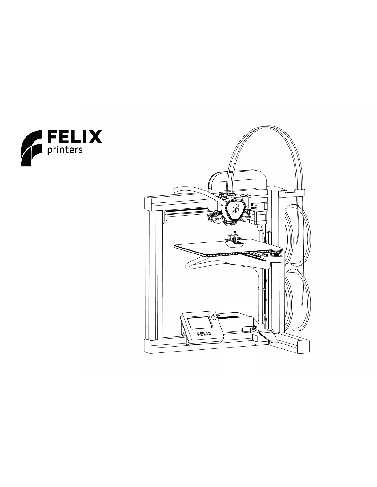
FELIX One
www.felixprinters.com
support@felixprinters.com
Zeemanlaan 15
3401 MV IJsselstein
The Netherlands
Version 1.0
2018
Page 2
FELIXprinters Assembly Manual for the FELIX One
Page 3
Dear Customer,
Thank you for choosing FELIXprinters! To get your Felix printer up
and running as fast and painlessly as possible please follow this manual carefully. Please don’t take any shortcuts. It’s better to spend a
few minutes extra on reading, than to wait a week for new parts.
When things are unclear or if you have any remarks or tips, please
contact us at support@FELIXprinters.com. We also recommend
looking on our forum and getting yourself a forum account. You will
benet from the ability to get downloadable and printable upgrades
for your printer. Also it is a great source to obtain and share knowledge about your 3D printer and 3D printing in general.
Have fun building!
Kind regards,
FELIXprinters.
Introduction Table of Content
Required tools 5
Chapter 1: Frame 6
Chapter 2: Z-axis 8
Chapter 3: X-axis 11
Chapter 4: Y-axis 15
Chapter 5: Print Head 19
Chapter 6: Wiring 27
Chapter 7: Upload Firmware 31
Chapter 8: Installing LCD 32
Chapter 9: Functional test 33
Chapter 10: Finishing Touch 35
Chapter 11: Checklist 36
Bill of Material 38
Page 3

FELIXprinters Assembly Manual for the FELIX One
Page 4
Notice
Before starting the assembling: Check the content of the kit if it is complete
according to the bill of material in the appendix of this document.
Page 4
FELIXprinters Assembly Manual for the FELIX One
Page 5
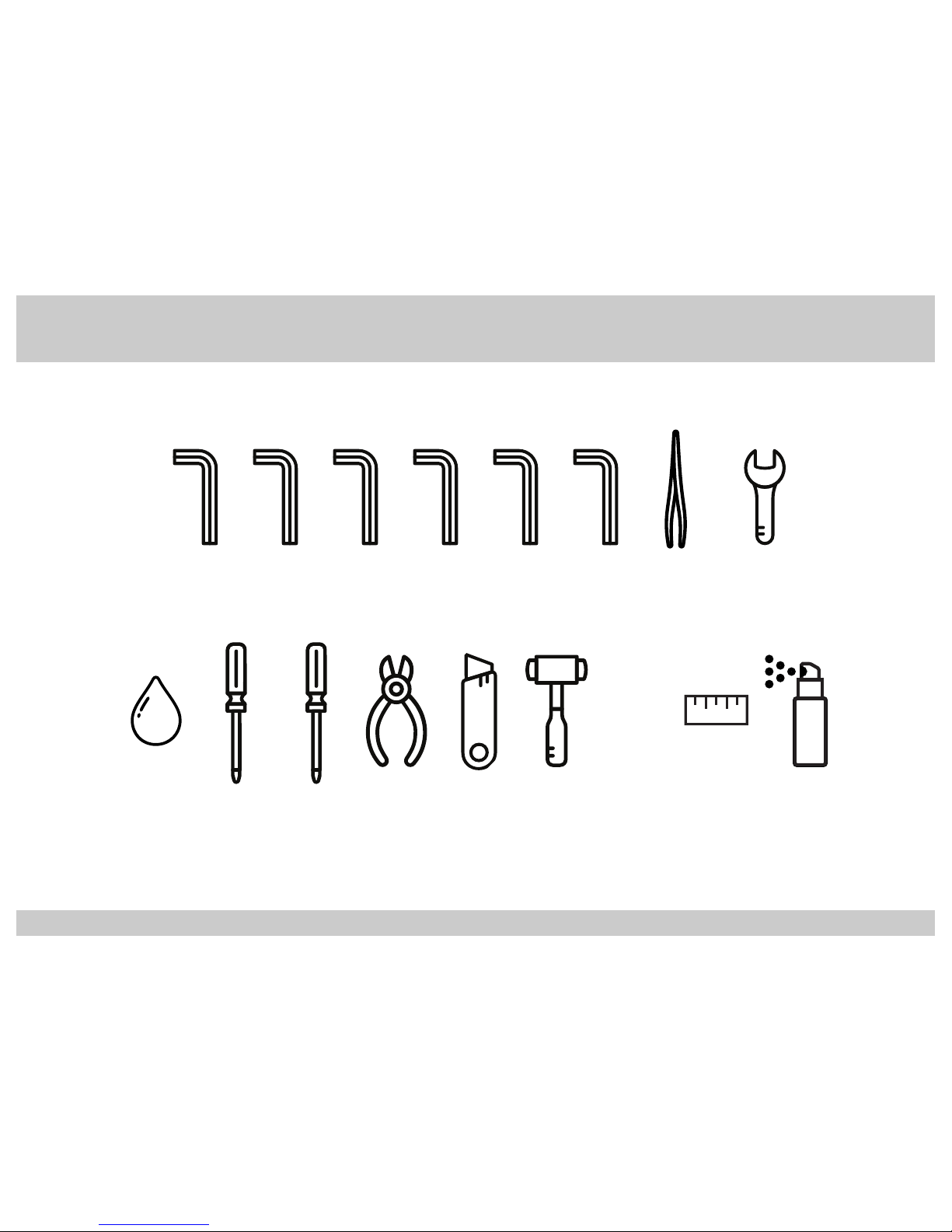
Required Tools:
*Or use a steel hammer with a soft piece
of rubber or plastic to absord the impact.
1,5 2 3 4 52,5
Hexagon
Key 1,5mm
Hexagon
Key 2mm
Hexagon
Key 2,5mm
Hexagon
Key 3mm
Hexagon
Key 4mm
Hexagon
Key 5mm
Tweezer
Wrench
5,5 mm 7,0 mm and 12 mm
5,5
7,0
12
+ -
Slotted Head
Screwdriver
Phillips Head
Screwdriver
Small
Pliers
Knife / Box
Cutter
Rubber
Hammer*
Grease
Lubricant
Tape
Measure
Alcohol
Page 5
FELIXprinters Assembly Manual for the FELIX One
Page 6
Tools:
3
1
Tools:
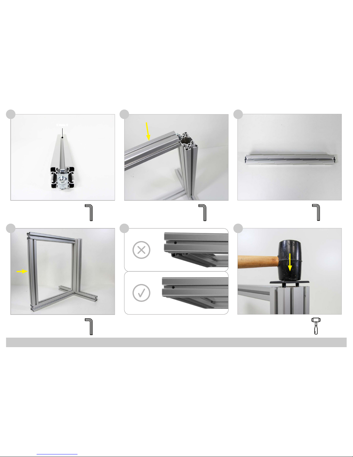
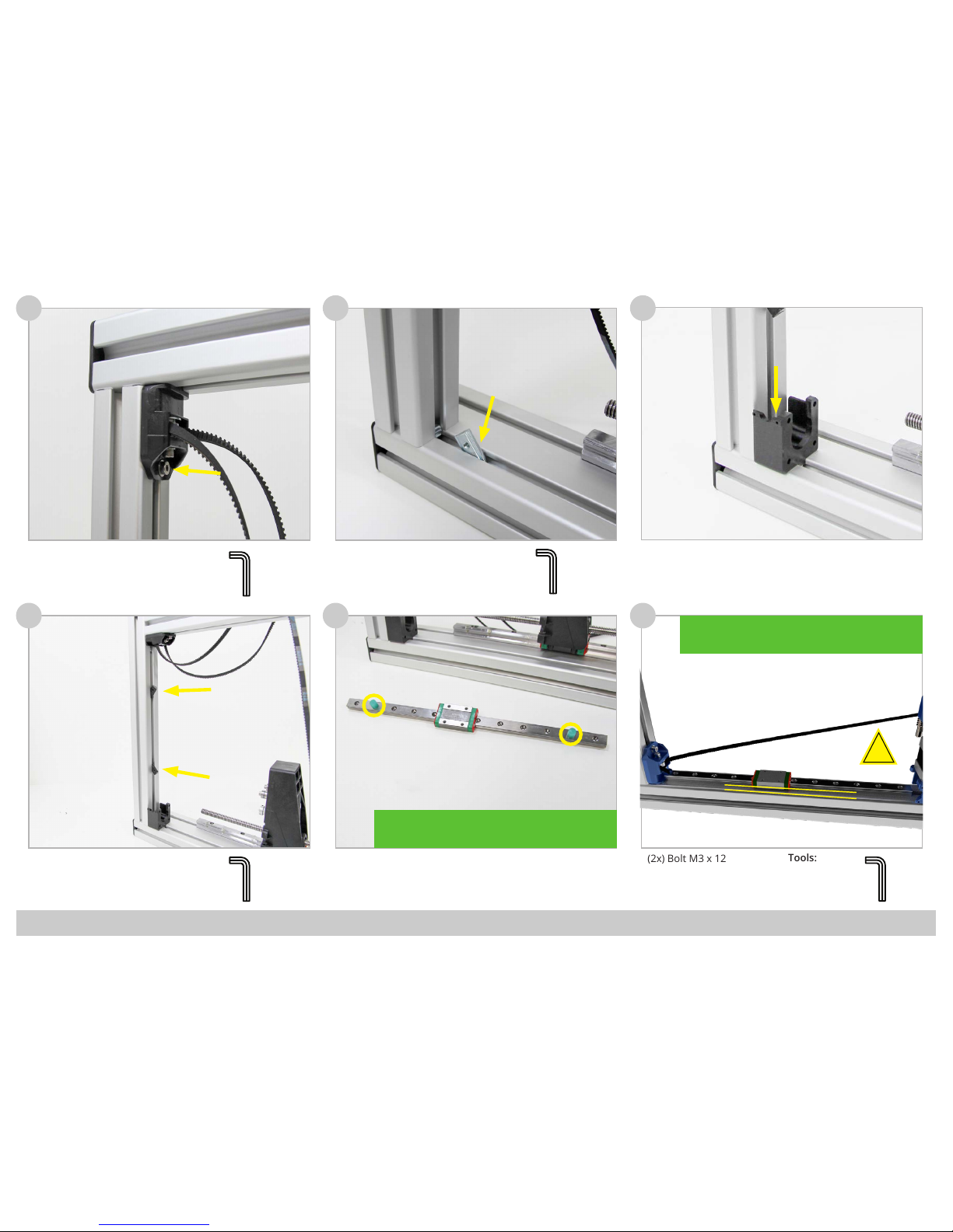
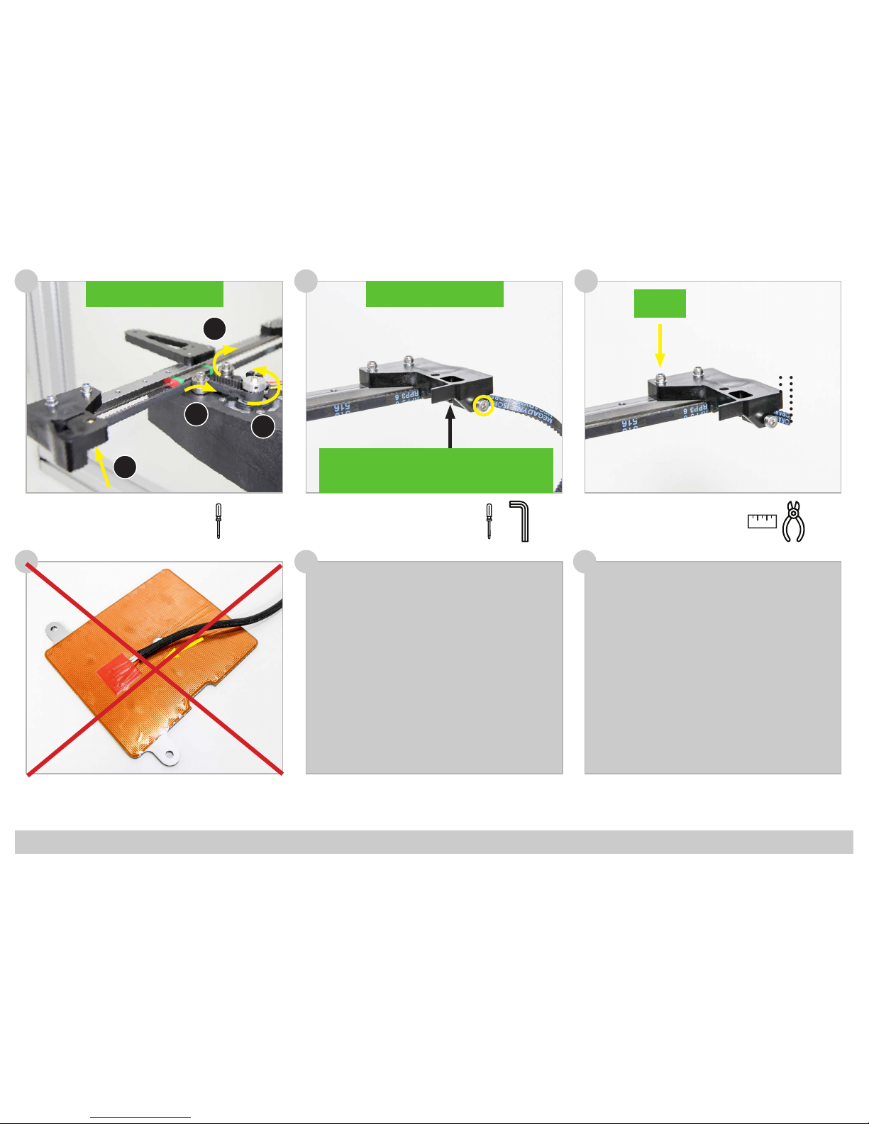
Chapter 1: Frame
30 Minutes
2
4 5
(1x) Prole 2
(1x) Bolt M8 x 20
(1x) Frame Connector
(1x) Prole 4
(2x) Bolt M8 x 20
(2x) Frame Connector
(1x) Prole 1
5
!! Hole !!
!! Hole !!
!! Hole !!
160mm
Tools:
5
!! Hole !!
!! Hole !!
!! Hole !!
!! Hole !!
!! Hole !!
160mm
Tools:
5
Tools:
5
5
Page 6
FELIXprinters Assembly Manual for the FELIX One
Page 7
Tools:
9
7 8
11
Make sure the proles are
properly aligned. If not
untighten the screws and
readjust the proles.
6
(4x) End Cap Square
(1x) End Cap Rectangle
!! Hole !!
(1x) Prole 2
(1x) Bolt M8 x 20
(1x) Frame Connector
Tools:
5
Tools:
5
(1x) Prole 3
(2x) Bolt M8 x 20
(2x) Frame Connector
Tools:
5
Tools:
5
10
Page 7
FELIXprinters Assembly Manual for the FELIX One
Page 8
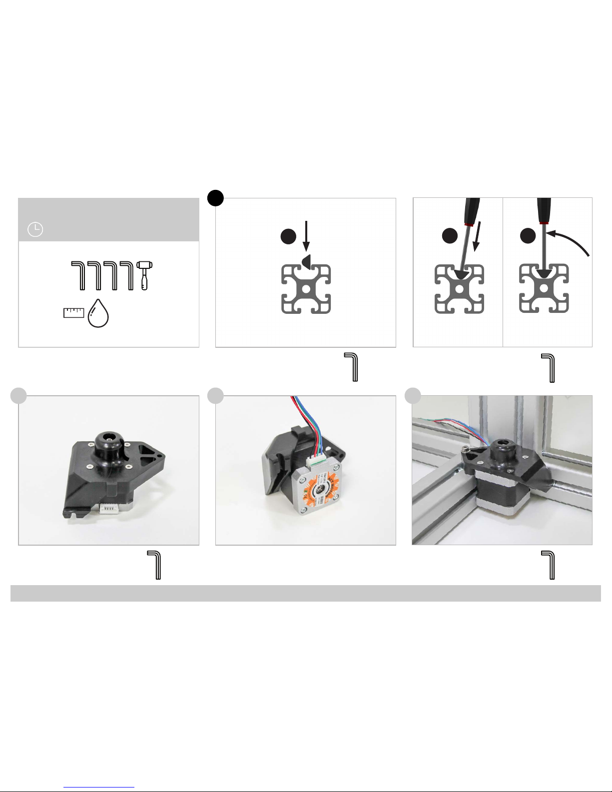
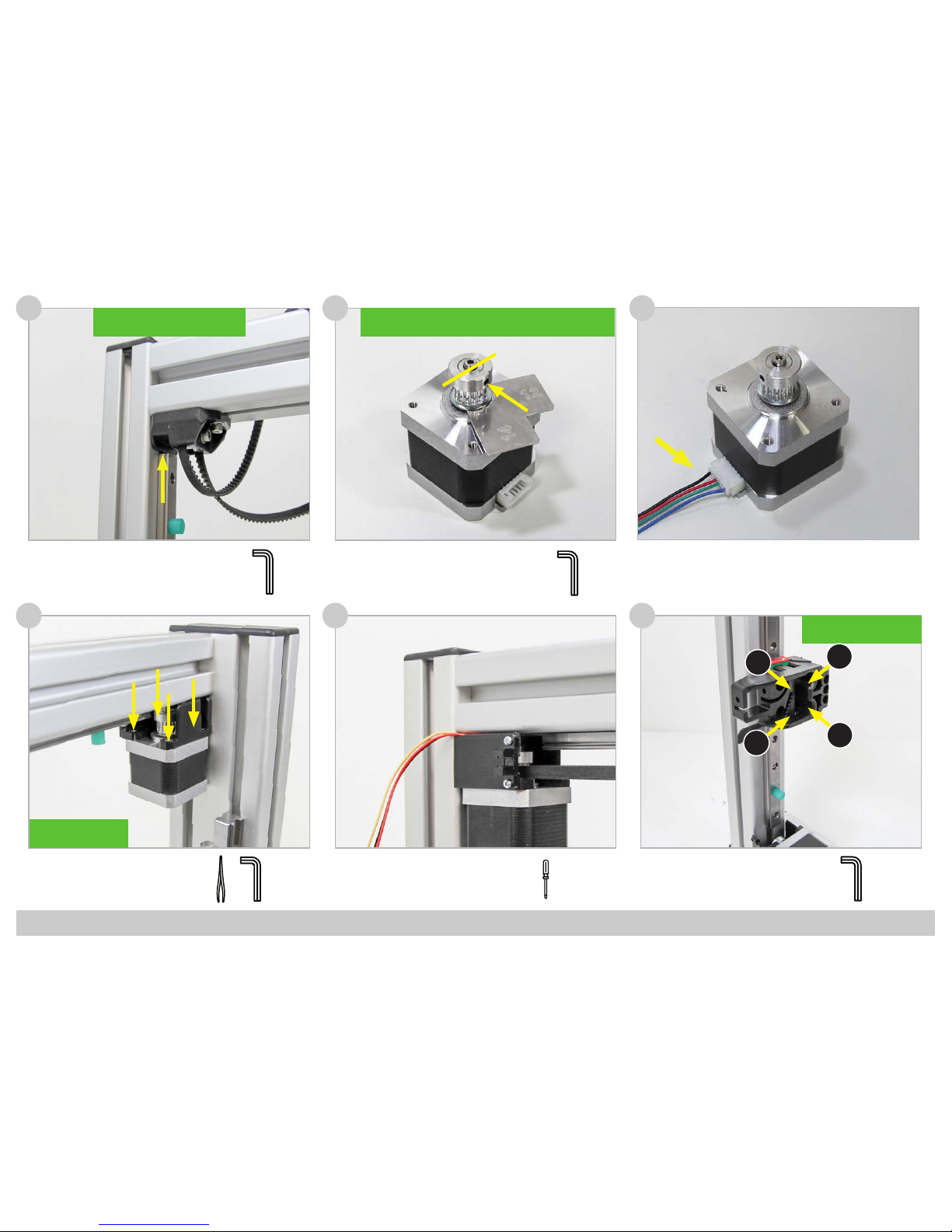
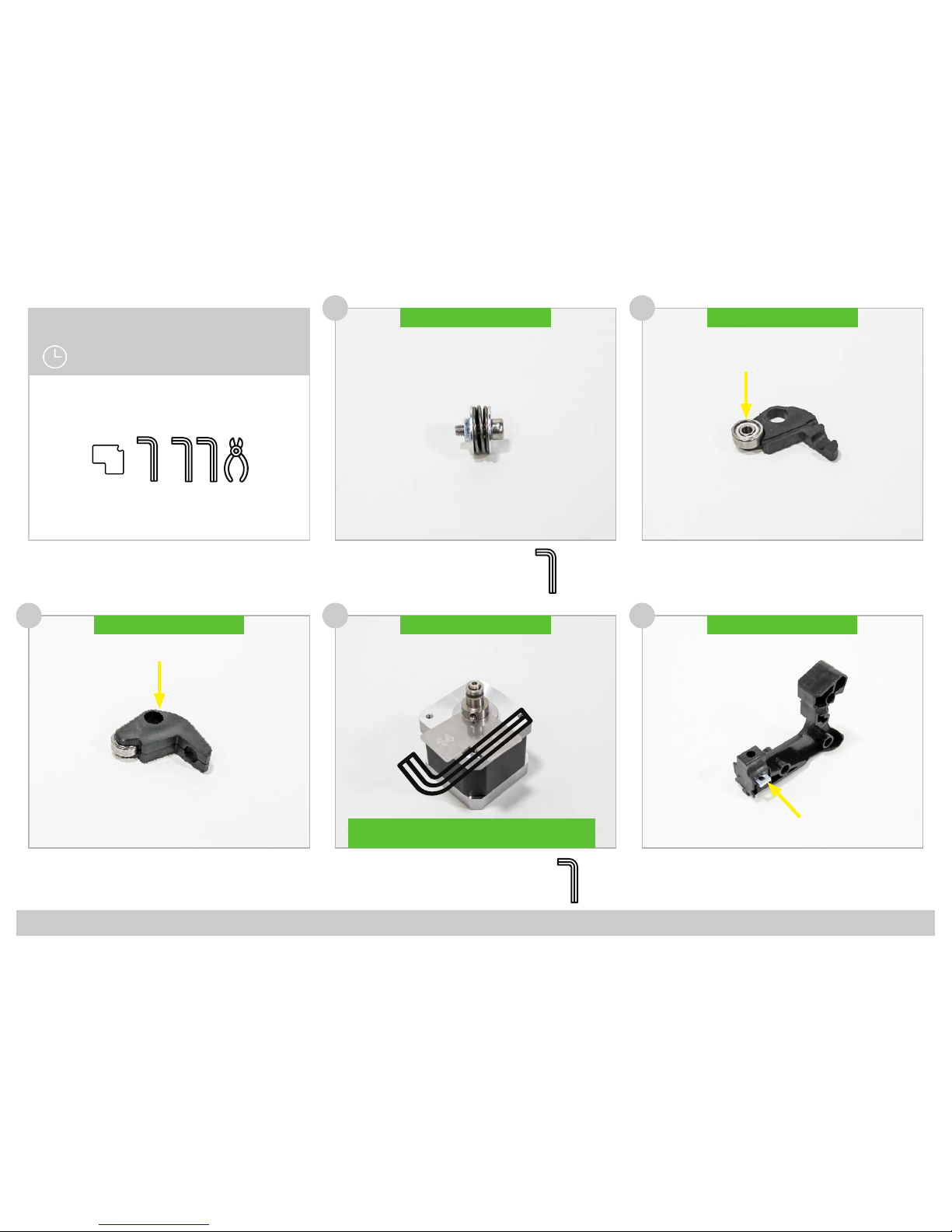
Tools:
12
(4x) CSK Bolt M3 x 8
(1x) Motor
(1x) Z-Axis Motor Bracket
13 14
(1x) Cable Stepper Z
i
(1x) Motor Assembly
(2x) T-Nut M4
(2x) Bolt M4 x 20
(2x) Small Washer M4
Example - Insert T-Nut:
Insert the nut into the slot
Tools:Example - Insert T-Nut:
Insert the key into the
threaded hole and rotate
the nut into position.
2
2
Tools:
2
Tools:
3
Tools:
Chapter 2: Z-Axis
45 Minutes
41,5 2 3
1
2 3
Page 8

FELIXprinters Assembly Manual for the FELIX One
Page 9
Tools:
18
(2x) Bolt M4 x 40
(2x) Locknut M4
16 17
19 20
(4x) Bearing
(2x) Bolt M4 x 25
(2x) Small Washer M4
(3x) Bolt M4 x 20
(1x) Linear Guide HGW15
Use tape measure to allign.
(1x) Z-Axis Lift
(1x) Hexagon Nut
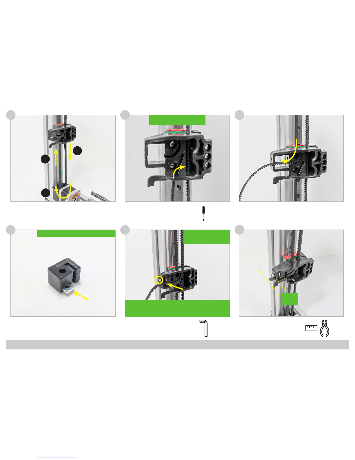
15
(3x) T-Nut M4
16cm
28cm
4cm
!! Don’t let the Carriage run of the Rail !!
Tools:
3
!! Remove Bolts after pulling Locknuts into Z-Axis Lift !!
!! Washer!!
!! Washer!!
Tools:
3
Tools:
3
Tools:
2
Page 9
FELIXprinters Assembly Manual for the FELIX One
Page 10
24
(1x) Motor Assembly
(4x) CSK Bolt M3 x 8
22 23
25 26
(1x) Spindle
(1x) Motor
(1x) Pulley
(1x) Set Screw M3 x 6
(1x) Cable Stepper Y
(1x) Cable Stepper Y
21
(1x) Z-Axis Lift Assembly
(4x) Bolt M5 x 16
(4x) Small Washer M5
(1x) Set Screw M3 x 6
Note: use a high quality and sharp 1.5 mm allen
key to properly x the spindle on the motor.
Tools:
4
Tools:
2
Tools:
1,5
Tools:
1,5
!! Make sure the Hexagon Nut
stays in its Socket !!
!! Make sure the at side of the Motor
Axle is Perpendicular to the Set Screw !!
!! Make sure the at side of the Motor Axle is Perpendicu-
lar to the Set Screw !!
Tools:
!! Apply Grease to the Spindle.
Do NOT use Oil as Lubricant !!
!! Tighten in a Crosswise
Pattern !!
4
2
1
3
Page 10
FELIXprinters Assembly Manual for the FELIX One
Page 11
29
(1x) Belt
27 28
30 31
(1x) T-Nut M4
(2x) Bearing
(1x) Small Washer M4
(1x) X-Axis Belt Mount
(1x) Bolt M4 x 40
(1x) T-Nut M4
Tools:
3
!! Washer !!
Tools:
3
Tools:
2
Tools:
2
(1x) X-Axis Belt Mount Assembly
Tools:
Chapter 3: X-Axis
60 Minutes
141,5
2 32,51,5
+
-
12
1
2
3
!! Make sure the short side of the T-nut is
facing the corner of the frame !!
Page 11
FELIXprinters Assembly Manual for the FELIX One
Page 12
!! Reposition the Safety Plugs as shown !!
Tools:
35
33 34
36 37
(2x) T-Nut M3 (black)
(1x) T-Nut M4
(1x) Bolt M4 x 16
(1x) Small Washer M4
(1x) X-Axis Motor Bracket
32
(1x) Bolt M4 x 16
(1x) Small Washer M4
(2x) Bolt M3 x 12
(1x) Linear Guide MGN12
Tools:
Tools:
3
Tools:
2
2
2,5
(1x) Linear Guide MGN12
!
14 mm
14mm from the side of the rail to side of the
frame!
Page 12
FELIXprinters Assembly Manual for the FELIX One
Page 13
Tools:
41
(1x) Motor Assembly
(4x) CSK Bolt M3 x 8
39 40
42 43
(2x) Small Screw 2,2 x 8
(1x) Opto Sensor X
(1x) Cable Stepper X
38
(4x) CSK M3 x 6
(1x) Extru Base
Tools:
!! Make sure to Position the Rail
against X-Axis Belt Mount !!
Tools:
2,5
(1x) Motor
(1x) Pulley
(1x) Set Screw M3 x 6
Tools:
1,5
!! Make sure the at side of the Motor Axle is Perpendicular
to the Set Screw !!
Tools:
2
!! Use Tweezer to
Position the Bolts !!
+
2
!! Tighten in a Crosswise
Pattern !!
1
3
4
2
Page 13
FELIXprinters Assembly Manual for the FELIX One
Page 14
Tools:
Tools:
47
(1x) Tension Bracket
(1x) Square Nut M4
46
48 49
(1x) Tension Bracket Assembly
(1x) Bolt M4 x 25
44
Tools:
-
!! Use a screwdriver to Push the
Belt completely into the Socket !!
!! Insert the Square Nut into the Tension Bracket !!
3
2 cm
!! Use the Screwdriver to
Push the Belt completely
into the Socket !!
1
2
3
!! Move the carriage to the center of the rail. Tighten the belt using
the size 3 hexagon key until the belts can barely touch eachother
when pressing them together !!
45
Page 14
FELIXprinters Assembly Manual for the FELIX One
Page 15
Tools:Tools:
52
(2x) Bolt M3 x 12
(1x) Y-Stage Bracket
50 51
53 54
(2x) Small Screw 2,2 x 8
(2x) Thin Nut M4
(1x) Opto sensor Y
(4x) Bolt M3 x 16
(4x) Locknut M3
(4x) Small Washer M3
(1x) Y-Stage Bracket Pt.1
(1x) Y-Stage Bracket Pt.2
(1x) Hiwin Linear Guide MGN12
(4x) Bolt M3 x 16
(4x) Small Washer M3
(1x) Y-Stage Assembly
!! (1x) Thin Nut M4 !!
!! (1x) Thin Nut M4 !!
+
!! Don’t let the Carriage run of the Rail !!
5,5
2,5
!! Endswitch Vane !!
Tools:
2,5
(1x) Tension Bracket
(1x) Bolt M4 x 25
(1x) Square Nut M4
Tools:
3
Tools:
2,5
!! Tighten in a Crosswise
Pattern !!
Tools:
Chapter 4: Y-Axis
30 Minutes
5,5
2,5
+3-
4
1
3
2
1
2
Page 15
FELIXprinters Assembly Manual for the FELIX One
Page 16
58
(1x) Build Platform
(1x) Short Wire Sleeve
56 5755
(1x) Belt Tools:
-
!! Use the Screwdriver to Push the
Belt completely into the Socket !!
Tools:
!! Use the Screwdriver to Push the
Belt completely into the Socket !!
-
3
Tools:
2 cm
2
1
3
4
Tensioning the Belt:
Move the Y-Axis completely to one end. Tighten the belt using the
size 3 hexagon key until the belt can barely touch the rail of the
Y-Axis
59 60
M3 x 25
Page 16
FELIXprinters Assembly Manual for the FELIX One
Page 17
65 66
(1x) Cable ties for mounting
cables on z bracket
64
(1x) Bolt M4 x 16
(1x) Spring
!! Tighten the Bolt against the end of the Thread !!
Tools:
3
End to End
25cm
Tools:
(1x) Cable ties for mounting
cables on z bracket
Tools:
!! Give the Cable enough Slack and tighten the Cable Tie !!
Tools:
62
(2x) Thumb screw
(2x) Spring
(1x) Build Platform Assembly
(2x) Cable Tie
63
!! Repeat for Front and Rear Thumbscrew !! !! Give the Cable enough Slack and tighten the Cable Ties !!
61
Page 17
FELIXprinters Assembly Manual for the FELIX One
Page 18
71
(1x) Extru Arm Pt. 2
69 70
72 73
(2x) Large Washer M4
(1x) Bolt M4 x 12
(1x) Thin Nut M4
(1x) Spring
(1x) Extru Arm Pt. 1
(1x) Bearing
(1x) L-Bracket
(1x) Square Nut M4
!! For Dual Head: Repeat this Step !! !! For Dual Head: Repeat this Step !!
!! For Dual Head: Repeat this Step !!
Tools:
3
!! For Dual Head: Repeat this Step !!
(1x) Motor
(1x) Extruder drive wheel
(1x) Set Screw M3 x 6
Tools:
1,5
!! Make sure the at side of the Motor Axle is Perpendicular
to the Set Screw !!
!! Repeat this Step !!
Tools:
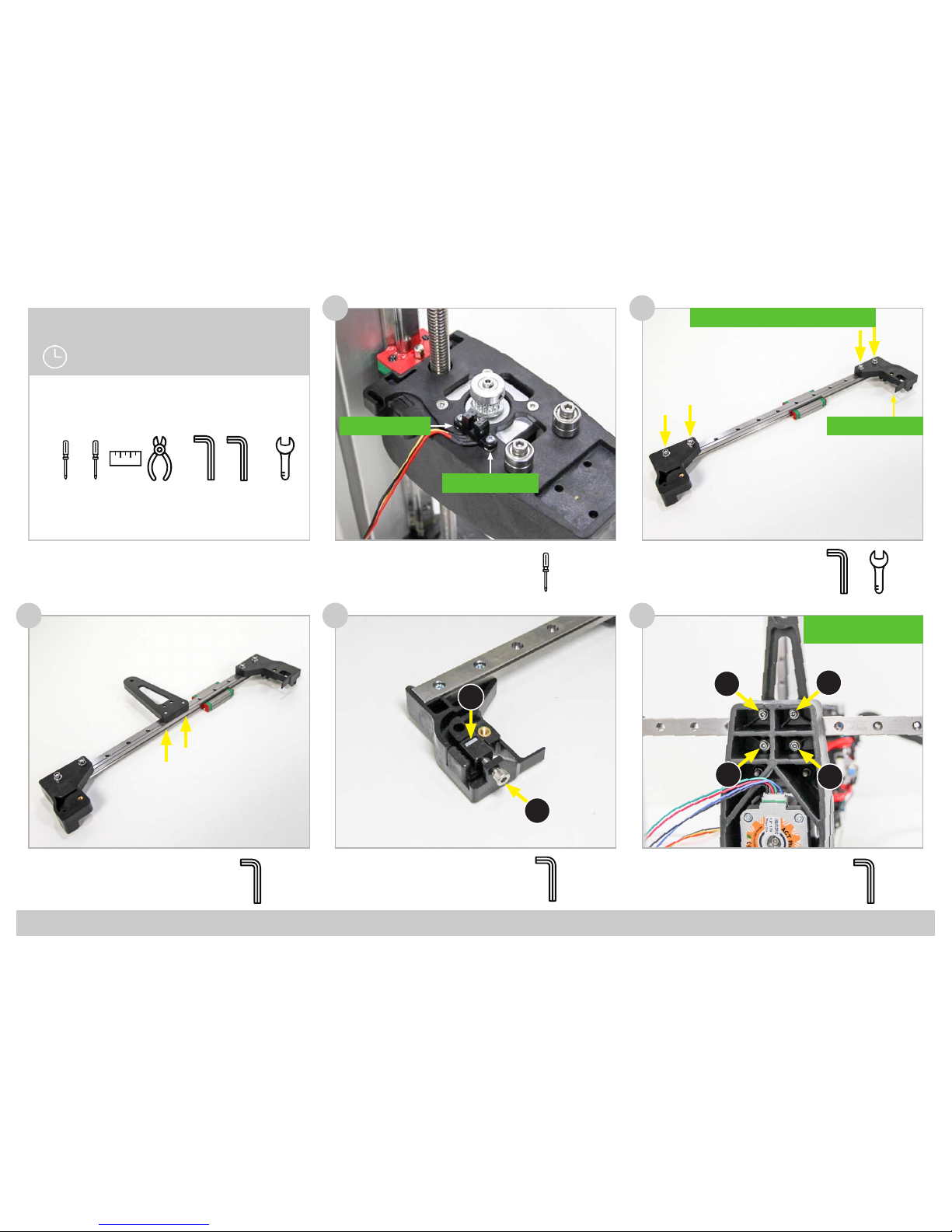
Chapter 5: Print Head
90 Minutes
1,5
1,5
32,5
Page 18

FELIXprinters Assembly Manual for the FELIX One
Page 19
77
(1x) L-Bracket
75 76
(3x) Bolt M3 x 16
(1x) L-Bracket Assembly
(1x) Motor
(1x) Square Nut M4
(1x) Extruder Arm Assembly
(1x) Spring Assembly
74
(1x) Bolt M4 x 40
Bolt is used to keep square nut
in place during assembly.
!! Repeat this Step !!
Tools:
3
Tools:
2,5
Motor E1
Motor E1 Motor E1
Page 19

FELIXprinters Assembly Manual for the FELIX One
Page 20
95
Label end of the hot-endcable: 0
96
Make sure the sticker from the fan is at the back.
The fan blows on the side of the sticker
Mount the bolt loosely.
Label end of the wire: 2
Align the print head on the carrier
Tools:
97
2,5
99
100
98
(2x M4) Place nuts for ease of
assembly.
Tools:
2,5
!
Tighten the bolt
!
Page 20

FELIXprinters Assembly Manual for the FELIX One
Page 21
95 96
(2x) Bolt M4 x 40 (used in step 74)
Connect sensor assembly and the
fan + LED onto the main assembly.
Tools:
97
2,5
99
100
98
(2x M4) Place nuts for ease of
assembly.
Tools:
2,5
Page 21

FELIXprinters Assembly Manual for the FELIX One
Page 22
Guide fan wires to front of bracket.
(3x) small cable tie
bundle cables, but do not tighten
too much.
Tools:
2 x
1 x
102101
103
(2x) print head assembly
Bend wires a little bit so they come to the front, while
heads are still parallel to each other.
(2x) M4 x 12
Connect extruder assembly by
placing two bolts.
(2x) normal cable tie
(1x) Long cable sleeve
Mount left motor wire and print head
wires together with cable bundle from
right side.
1. Remove nuts (placed in step 98)
2. (1x) small cable tie
Mount front assembly. Bundle print
head wires, motor wire and sensor
wire. Place cable tie loosely.
Tools:
Tools:
Tools:
2,5
104 105 106
2,5
Page 22

FELIXprinters Assembly Manual for the FELIX One
Page 23
1. Place explate on top of buildplate.
2. Move z-sensor above leveler wheel.
3. Move platform up, until left or right hot-end touches build
plate.
4. Adjust height of z-sensor, until the distance between sensor
and leveler wheel is the thickness of the calibration card.
107
(Detailed Z-height calibration process is explained in the Quick Start Guide)
Page 23

FELIXprinters Assembly Manual for the FELIX One
Page 24
Tools:
110
(1x) Single Cable Clip
108
Tools:
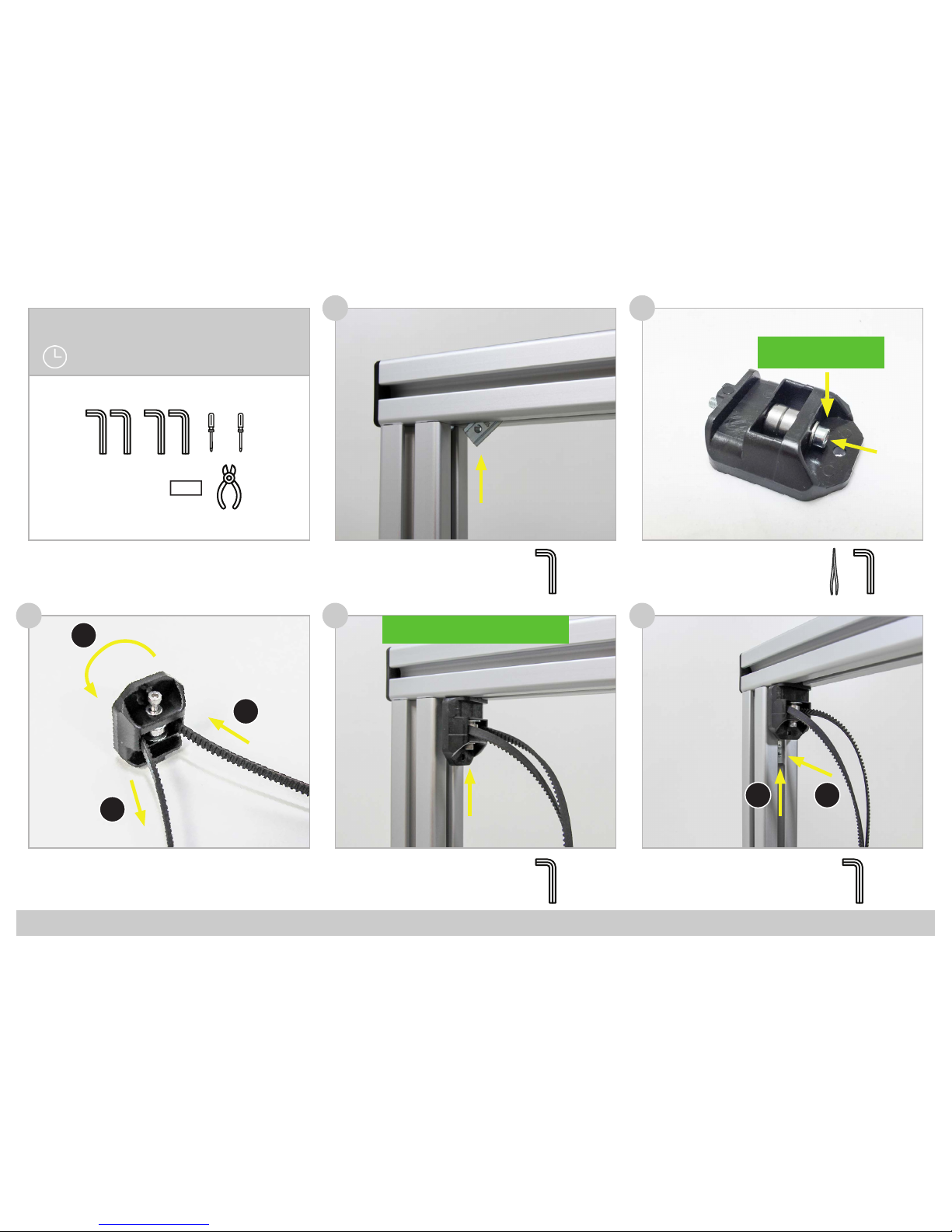
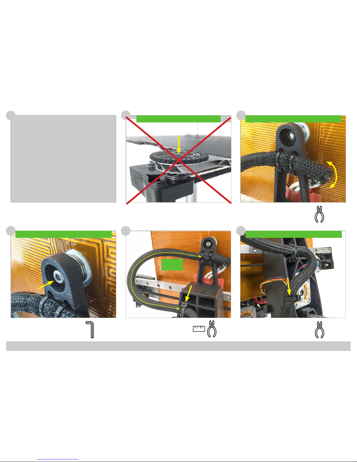
Chapter 6: Wiring
60 Minutes
109
111
112
(2x) Single Cable Clip
(2x) Dual Cable Clip
(2x) Single Cable Clip
(1x) Angled Cable Clip
24cm
End to End
38cm
Tools:
Tools:
Tools:
3
+
Page 24

FELIXprinters Assembly Manual for the FELIX One
Page 25
Tools:
116
114
115
117
113
(1x) Electronic Enclosure
Assembly
Tools:
118
Tools:
3
Tools:
1x Y-stage bracket pt1
1x Y-stage bracket pt2
4x Bolt M3x16
4x Smal washer M3
4x Self locking nut M3
Tools:
1x Bolt M3x8
1x Small t-slot M3
1x Y stage tensioning bracket
1x Thin nut M4
1x Bolt M4x25
Page 25

FELIXprinters Assembly Manual for the FELIX One
Page 26
116
114
115
117
113
Tools:
118
ATTENTION: Bottom of set-screw should NOT touch
plate internally. Keep distance of approx. 0.5mm
!
3x Set screw M4x30
3x Thin nut M4
Large washer
3x spring
2x Small washer
1x Large washer
3x Thin nut M4
!
Tighten the nuts a couple of turns, make sure that
the springs are still able to compress for further
ne-adjustment later.
2x tie-wrap
Page 26

FELIXprinters Assembly Manual for the FELIX One
Page 27
116
114
115
117
113
118
1x 25 cm Cable spiral
Belt
Mount the belt, according to the arrows.
!
+/- 1cm
Page 27

FELIXprinters Assembly Manual for the FELIX One
Page 28
116
114
115
113
1x 25 cm Cable spiral
1x Clamp + Cable tie
Ends of the plastic strip must be cut at an angle
!
!
1x 13 cm Plastic U-prole
The y-axis and the print bed
are nished.
Page 28

FELIXprinters Assembly Manual for the FELIX One
Page 29
Tools:
116
(1x) Electronic Enclosure
Cover Plate
114
115
117
(2x) T-Nut M4
(2x) Bolt M4 x 12
(2x) Power Supply Screw
(1x) Power Supply
(1x) Electronic Enclosure
Pt. 2
(2x) Power Supply Screw
(1x) Electronic Enclosure
Pt. 1
113
(1x) Electronic Enclosure
Assembly
Tools:
118
23cm
Tools:
End to End
25 cm
Tools:
+
Tools:
+
!! Position the narrow edge upwards!!
3
!! Make sure to position the left
T-Nut against the prole !!
!! First slide the Enclosure against
the left T-Nut, next slide the right
T-Nut with Bolt into the Slot.
Finally tighten the Two Bolts !!
3
1
2
Page 29

FELIXprinters Assembly Manual for the FELIX One
Page 30
Important:
1. Set the Blue Potentiometers
to the correct value as shown
in the overview.
2. Tighten the screw terminals
with force to ensure a good
connection.
3. Make sure the Control board
is positioned correctly, so
that the underside doesn’t
touch the power supply.
Overview:
Control Board
119
120
121
Black
Green
Blue
Red
Blue
Green
Red
Black
Main board side
Motor side
Note:
E0 = E1
on control board
Page 30

FELIXprinters Assembly Manual for the FELIX One
Page 31
125
123 124
(1x) Display Assembly
(1x) Control Board
122
(4x) Square Nut M4 Tools:
!! Plug the connector into the
matching socket description !!
end X = Endswitch X (Opto sensor)
end Y = Endswitch Y (Opto sensor)
Z sensor cable has no label.
Page 31

FELIXprinters Assembly Manual for the FELIX One
Page 32
Download the Firmware:
Download the latest FELIX One Firmware version from:
http://www.felixprinters.com/downloads_felixprinters
Upload the Firmware to the Control Board:
1. Unzip the downloaded le to a convenient location.
(Note: if you click on the zip le from within the Windows explorer, it will NOT be unzipped. You just
view the content of the zip. You need to select the les and drag them to the desired location.)
2. Connect your printer to your computer and turn it on. Do not make a connection at this time with
the printer with programs like Repetier-Host or Simplify3D.
3. Start the batch le “upload_automatic.bat”. A script will start in a command window.
4. The script will try to detect what COM port your printer is using. Check if this is correct, and then
proceed by entering ‘Y’ in the command window.
5. The rmware is uploaded when ‘’Programming nished!’’ is displayed, this may take a few minutes.
6. Press any key to continue. The FELIX One rmware is now successfully uploaded.
Note for Experienced Users: Due to compatibility issues with linux based systems, the baudrate for the
FELIX Tec 4 is lowered to 115200. Make sure to adjust the settings in the used software accordingly.
Chapter 7: Upload Firmware
15 Minutes
Page 32

FELIXprinters Assembly Manual for the FELIX One
Page 33
125
123 124
126
(1x) Display Interface PCB
(1x) Display Assembly
122
2x Small screw 2,2 x 8
10
1x Plastic Display-cover
Page 33

FELIXprinters Assembly Manual for the FELIX One
Page 34
127
128
130
(6x) Damping Feet
!! Clean the surface of the
frame rst before apply-
ing the damping feet !!
Tools:
(2x)
(2x) (2x)
128
!
Connecting the display cables
Align the square nuts from step
88 properly before mounting the
cover with the m4x12 bolts.
130
Page 34

FELIXprinters Assembly Manual for the FELIX One
Page 35
Chapter 9: Functional Test
10 Minutes
In order to make sure all motors, sensors and LCD panel are connected properly, the following tests need to be performed
Z-sensor
The z-sensor can be tested by holding a metal object underneath the sensor. Check if the z-sensor LED turns o.
When the z-sensor indication LED on the main board switches o, the sensor is activated.
Y-sensor
Manually move the bed to its end position to activate the y-sensor. Check if the y-sensor LED turns o.
When the y-sensor indication LED on the main board switches o, the sensor is activated.
X-sensor
Manually move the extruder to its end position to activate the x-sensor. Check if the x-sensor LED turns o.
When the x-sensor indication LED on the main board switches o, the sensor is activated.
Check Sensor Connections:
Main board Tec 4
IMPORTANT: Keep hand near ON/OFF switch of printer, in case things go wrong.
Warm up left extruder (E1).
Note: The hot-ends might smell a bit the rst time heating. This is because of a small amount of oil within certain parts.
Click rotary button to enter the main menu --> Control --> scroll down to heater --> Click on E1 and rotate until setpoint
temperature increases to about 100 degC. Then check if temperature for that heater goes up.
Repeat these steps for the right extruder (E2) and for the Bed (55degC).
Check heaters:
Page 35

FELIXprinters Assembly Manual for the FELIX One
Page 36
Check Motor Cable Connections:
IMPORTANT: Keep hand near ON/OFF switch of printer, in case things go wrong.
X-axis motor
To make sure the wires are connected as required it is important to test all connections.
To do so for the x-axis: enter menu by pushing the rottary button --> Control --> Move --> Home X
Y-axis motor
To test the y-axis: enter menu by pushing the rottary button --> Control --> Move --> Home Y
Z-axis motor
NOTE: When doing home z, extruders heatup to 120 DegC to prevent possible lament blobs from scratching the kapton surface layer.
Important: ensure explate is placed on the print bed.
To test the z-axis: enter menu by pushing the rottary button --> Control --> Move --> Home Z
Page 36

FELIXprinters Assembly Manual for the FELIX One
Page 37
Tools:
(1x) Kapton Foil
Tools:
Chapter 10: Finishing Touch
15 Minutes
132
!! Peel o the protective sheet at the
corner and stick the exposed adhesive
to the BuildPlate at one corner !!
!! Continue peeling o the protective sheet and at the
same time stick the foil to the BuildPlate using a soft
object in a zigzag motion to avoid air bubbles !!
1
2
131
Preheat your buildplate to 60 C
degrees to make sure the Kapton
Foil will have good adhesion to the
exible plate.
Tools:
(4x) M4 x 12
(1x) Electronic Enclosure
Cover
133
!! Use the Screwdriver to
center the Square Nut be-
fore inserting the Bolts !!
3
+
134
(1x) Main Fan Cover
Connect the fan cover onto the extruder unit.
3
+
Page 37

FELIXprinters Assembly Manual for the FELIX One
Page 38
Chapter 11: Checklist
Frame:
1. Frame bolts (6x) are properly xed.
2. Frame proles are perpendicular and propely aligned.
3. Damping feet are placed underneath the printer.
X-axis:
1. X-axis rail is properly aligned.
2. Bolts (2x) X-axis rail are properly xed.
3. X-axis belt pushed fully into bracket and tensioner.
4. Belt remains at same height during moving the X-axis.
5. Set screw (1x) for pulley is xed at the correct height with set
screw.
6. X-axis belt tensioned properly
Y-axis:
1. Bolts for stacked bearings (4x) guiding the belt are properly
xed.
2. Y-axis carriage is properly aligned in the Z-axis lift.
3. Bolts (4x) of the Y-axis carriage are properly xed.
4. Y-axis belt pushed fully into bracket and tensioner.
5. Belt remains at same height during moving the Y-axis.
6. Set screw (1x) for pulley is xed at the correct height with set
screw.
7. Y-axis belt tensioned properly.
Z-axis:
1. Z-axis rail is properly aligned.
2. Bolts (3x) Z-axis rail are properly xed.
3. Set screw (1x) Z-axis spindle is properly xed.
4. Bolts (4x) connecting Z-axis carriage to the lift are propely
xed.
5. Z-axis spindle nut is properly tted in the Z-axis lift.
6. Z-axis spindle is greased over its entire length.
Build Platform:
1. Bolt (1x) center of build platform is properly xed.
2. Build surface doesn’t contain air bubbles.
Print Head:
1. Extruder drive wheels properly aligned.
2. Bolts (2x) connecting print head to X-axis carriage are pro-
perly xed.
3. Bolts (2x) sensor bracket are properly xed.
Electrical:
1. Wire harness properly xed without rubbing against parts.
2. Wire harness loop for X, Y, Z-axis are at the correct length
and do not get pulled under full extension.
3. Cables are not under tension and have enough slack.
4. Cable ties neatly cut o.
5. Connectors properly connected in sockets.
6. Potentiometers on control board are set to the correct values.
7. Control board contains the correct Tec 4 rmware version.
8. Wire colors are according to diagram.
Online Test:
1. Build platform heats up to 90 degrees C, move cable harness
to check for wire breakage.
2. Extruders heat up to 90 degrees C, move cable harness to
check for wire breakage.
3. Hot-ends don’t move during loading/unloading lament.
4. Check if lament gets pulled through rmly.
Page 38

FELIXprinters Assembly Manual for the FELIX One
Page 39
Congratulations!
You have nished building the FELIX One.
Continue to the Quick Start Guide to start printing!
Page 39

FELIXprinters Assembly Manual for the FELIX One
Page 40
Bill of Material
Part
Quantity
#140 011.0 Set screw D-916 - M3 x 6-N -
5
#140 012.0 Bolt D-7991- M3 x 6 --- 6N - CSK
5
#140 013.0 Bolt D-7991- M3 x 8 --- 8N - CSK
15
#140 016.0 Hexagon socket head cap screw DIN 912 - M3 x 12
5
#140 017.0 Hexagon socket head cap screw DIN 912 - M3 x 16
14
#140 018.0 Hexagon socket head cap screw DIN 912 M4 x 12
12
#140 019.0 Hexagon socket head cap screw DIN 912 M4 x 16
2
#140 020.0 Hexagon socket head cap screw DIN 912 M4 x 20
7
#140 021.0 Hexagon socket head cap screw DIN 912 M4 x 25
4
#140 022.0 Hexagon socket head cap screw DIN 912 M4 x 40
2
#140 023.0 Hexagon socket head cap screw DIN 912 M5 x 16
5
#140 024.0 WasherD-125A M3
6
Bolts and nuts set
Page 40

FELIXprinters Assembly Manual for the FELIX One
Page 41
Part
Quantity
#140 011.0 Set screw D-916 - M3 x 6-N -
5
#140 012.0 Bolt D-7991- M3 x 6 --- 6N - CSK
5
#140 013.0 Bolt D-7991- M3 x 8 --- 8N - CSK
15
#140 016.0 Hexagon socket head cap screw DIN 912 - M3 x 12
5
#140 017.0 Hexagon socket head cap screw DIN 912 - M3 x 16
14
#140 018.0 Hexagon socket head cap screw DIN 912 M4 x 12
12
#140 019.0 Hexagon socket head cap screw DIN 912 M4 x 16
2
#140 020.0 Hexagon socket head cap screw DIN 912 M4 x 20
7
#140 021.0 Hexagon socket head cap screw DIN 912 M4 x 25
4
#140 022.0 Hexagon socket head cap screw DIN 912 M4 x 40
2
#140 023.0 Hexagon socket head cap screw DIN 912 M5 x 16
5
#140 024.0 WasherD-125A M3
6
#140 025.0 WasherD-125A M4
10
#140 026.0 WasherD-125A M5
5
#140 028.0 Corrosserie ring - M4 - large washer
2
#140 029.0 Prevailing torque type hexagon nut DIN-985 - M3
6
#140 030.0 Prevailing torque type hexagon nut DIN-985 - M4
6
#140 031.0 Hexagon Thin Nut D-439B - M4
8
#140 032.0 Powersupply screw UNC 6/32 x 1/4 Pozi steel
6
#140 037.0 Set screw D-916 - M4 x 30
2
#140 039.0 Spring Extruder & bed
4
#140 040.0 Thin square nut DIN 562 - Steel - M4
9
#110 021.0 t_slot nut - 8 ST M3
3
#140 070.0 Parker 2.2 x 8 - plaatschroef
6
Page 41

FELIXprinters Assembly Manual for the FELIX One
Page 42
Prod. Nr.
Desciption
Total
Image
105 021.0
Electronics bag
150 155.0
Opto sensor X (Straight) , cable and connectorTec4
1
150 156.0
Opto sensor Y (Angled) cable + connector Tec4
1
105 028.0
Z-sensor calibration unit
1
150 159.0
Double fan with cable and connector Tec4
1
Page 42

FELIXprinters Assembly Manual for the FELIX One
Page 43
170 013.0
cable ties, tie wrap - 100mm x 2.5 mm
1
170 021.0
Cable ties for mounting cables on Z bracket
2
170 015.0
Cable sleeve, nylon semi open set 95/ 115 cm
2.1
150 150.0
Stepper Extruder0 cable Tec4
1
150 152.0
Stepper X -axis cable Tec4
1
Page 43

FELIXprinters Assembly Manual for the FELIX One
Page 44
150 153.0
Stepper Y -axis cable Tec4
1
150 154.0
Stepper Z-axis cable Tec4
1
Prod. Nr.
Desciption
Total
Image
105 020.0
Mechanic bag felix Tec4
135 004.0
Pulley motor - FELIX 3 and Pro series
2
135 003.0
Tooth Belt
1
135 005.0
bearing 624, 4x13x6 (packaged per 10)
7
130 016.1
Extruder drive wheel FELIX 3/Tec4
1
Page 44

FELIXprinters Assembly Manual for the FELIX One
Page 45
Prod. Nr.
Desciption
Total
Image
105 020.0
Mechanic bag felix Tec4
135 004.0
Pulley motor - FELIX 3 and Pro series
2
135 003.0
Tooth Belt
1
135 005.0
bearing 624, 4x13x6 (packaged per 10)
7
130 016.1
Extruder drive wheel FELIX 3/Tec4
1
130 035.0
platform support Felix Tec4 (Y-Bracket F3.5)
1
130 041.0
Knurled thumb knob tec4
2
130 043.0
Z-adjustment right hot-end
1
130 042.0
Fan finger guard 40x40 mm tec4
2
130 044.0
Dual Extruder Front Bracket - Tec 4
1
160 017.0
Spacer rail and extruder wheel adjustment for Felix3.X
1
Page 45

FELIXprinters Assembly Manual for the FELIX One
Page 46
Prod. Nr.
Desciption
Total
Image
Parts packet separately in DIY kit
150 023.0
Powersupply - FELIX 3.0
1
130 017.0
Spindle - trapezium - Felix 3
1
105 127.0
Assy build platform Felix Tec4
1
135 001.0
Hiwin linear ball bearing - MGN12H1R0300Z1HM
2
135 002.0
Hiwin linear ball bearing - HGW15CC1R300Z0
1
Page 46

FELIXprinters Assembly Manual for the FELIX One
Page 47
Prod. Nr.
Desciption
Image
105 047.0
Set plastic parts
122 012.0
X_stage_F3_0_belt _mount_v1 - black
1
105 064.0
Y stage bracket prt1 with inserts Felix Tec4 Black
1
105 065.0
Y stage bracket prt2 with inserts Felix Tec4 Black
1
122 015.0
Y_stage_F3_0_tensi oning_bracket_v1 - black
2
122 016.0
z_axis_F3_0_lift_part_v1 - black
1
122 017.0
z_axis_F3_0_motor_bracket_v1 - black
1
Page 47

FELIXprinters Assembly Manual for the FELIX One
Page 48
122 019.1
Extru_F3_1_base - black
1
122 020.1
Extru_F3_1_L_shap e_bracket - black
3
122 021.0
Extru_F3_0_arm_pt1_v1 - black
2
122 022.0
Extru_F3_0_arm_pt2_v1 - black
2
122 025.0
Electronics_enclosure_F3_0 _cap_pt1 - black
1
122 026.0
Electronics_enclosure_F3_0 _cap_pt2 - black
1
Page 48

FELIXprinters Assembly Manual for the FELIX One
Page 49
122 028.0
Electronics_encl osure_F3_0_cover_plate_v1 - black
1
122 031.0
Electronics_enclosure Felix Tec4 Black
1
170 017.0
Sticker on control box, TEC 4
1
122 039.0
Fan Cap airduct Tec4 - Black
2
122 040.0
Fan front cover Tec4 - black
1
122 037.0
Printed parts LCD cabinet Felix Tec4 - Black
1
122 011.0
X_stage_F3_0_motor_bracket_v1 - black
1
Page 49

FELIXprinters Assembly Manual for the FELIX One
Page 50
Prod. Nr.
Desciption
Total
Image
105 124.0
FULL metal hotend FELIX Tec
130 110.0
nozzle_felixprinters (0,35 mm pro1)
1
130 029.0
Hotend bas e Felix Tec4
1
130 030.0
Heat break Felix Tec4
1
150 013.0
Felix 3 & Tec 4 - Heater Cartridge incl. connector
1
130 109.0
Hot End Heated Barrel 1.75 Pro1
1
150 162.0
FELIX 3.1 & Tec4 - Thermistor incl. connector
1
130 031.0
Teflon tube Hot-end (36,5 mm) Felix Tec4
1
140 036.0
Set screw D-916 - M3 x 4
3
Page 50

FELIXprinters Assembly Manual for the FELIX One
Page 51
Prod. Nr.
Desciption
Total
Image
105 051.0
Frame bag Felix3/ Tec4
110 017.0
frame connector set
6
110 018.0
handle PA 160 for Felix3
1
110 019.0
Protective cap, handle PA160, FELIX 3
1
110 022.0
T-slot nuts 8 ST M4
12
110 024.0
t_slot nut - 8 ST M8
2
110 015.0
40x40 protective caps
4
110 016.0
80x40 protective caps
1
110 025.0
damping foot (felix 3)
6
140 035.0
bolkop inbus bol t M8x16 ITEM
2
Page 51

FELIXprinters Assembly Manual for the FELIX One
Page 52
Prod. Nr.
Desciption
Total
Image
105 050.0
Frame profile set Felix3/ Tec
profiel 8 40x40x400 E PT1
1
profiel 8 40x40x400 E PT3
2
profiel 8 40x40x400 E PT4
1
profiel 8 80x40x440 E
1
Page 52

FELIXprinters Assembly Manual for the FELIX One
Page 53
Prod. Nr.
Desciption
Total
Image
105 019.0
Miscellaneous Felix 3.1/ Tec4
150 018.0
USB cable 1.8m
1
170 011.0
Tweezers
1
170 019.1
Teflon Tube for Pro and 3 series - (55cm)
2
170 023.1
Filament dust cleaner
1
180 001.1
PLA sample - 50 gram - Random Colours
1
122 045.0
Filament guide/ dust cleaner holder Fel ix3/ Tec (printed)
1
122 044.0
Filament bracket Felix3/ Tec (printed ) - black
2
Page 53

FELIXprinters Assembly Manual for the FELIX One
Page 54
Prod. Nr.
Desciption
Total
Image
Optional parts depending on region
150 019.0
Power cabl e EU
1
150 020.0
Power cable US
1
150 021.0
Power cable AU
1
150 022.0
Power cable UK
1
Page 54

FELIXprinters Assembly Manual for the FELIX One
Page 55
Prod. Nr.
Desciption
Total
Image
105 031.0
Upgrade Single Tec to Dual Felix Tec 4
150 027.1
Stepper motor Nema 17, 40 mm
1
150 151.0
Stepper Extruder1 cable Tec4
1
130 016.1
Extruder drive wheel FELIX 3/Tec4
1
140 017.0
Hexagon socket head cap screw DIN 912 - M3 x 16
3
105 124.0
Full metal hotend FELIX Tec
1
140 039.0
Spring Extruder & bed
1
140 028.0
Corrosserie ring - M4 - large washer
2
140 018.0
Hexagon socket head cap screw DIN 912 M4 x 12
1
Optional: depending on order
Page 51
Page 55

FELIXprinters Assembly Manual for the FELIX One
Page 56
140 031.0
Hexagon Thin Nut D-439B - M4
1
135 005.0
bearing 624, 4x13x6 (packaged per 10)
1
170 019.1
Teflon Tube for Pro and 3 series - (55cm)
1
170 023.1
Filament dust clean er
1
105 128.0
set Tie wraps 20 pieces in bag
1
Optional: depending on order
 Loading...