

Page 1

1
Caution:
This device complies with Part 15 of the FCC Rules / Innovation, Science and Economic
Development Canada’s licence-exempt RSS(s).Operation is subject to the following two conditions:
(1) this device may not cause harmful interference. (2) this device must accept any interference
received, including interference that may cause undesired operation.
L’émetteur/récepteur exempt de licence contenu dans le présent appareil est conforme aux CNR
d’Innovation, Sciences et Développement économique Canada applicables aux appareils radio
exempts de licence. L’exploitation est autorisée aux deux conditions suivantes :
1. L’appareil ne doit pas produire de brouillage;
2. L’appareil doit accepter tout brouillage radioélectrique subi, même si le brouillage est susceptible
d’en compromettre le fonctionnement.
Changes or modifications not expressly approved by the party
responsible for compliance could void the user's authority to operate the
equipment.
This equipment has been tested and found to comply with the limits for
a Class B digital device, pursuant to part 15 of the FCC Rules. These
limits are designed to provide reasonable protection against harmful
interference in a residential installation. This equipment generates
uses and can radiate radio frequency energy and, if not installed and
used in accordance with the instructions, may cause harmful interference
to radio communications. However, there is no guarantee that interference
will not occur in a particular installation. If this equipment does cause
harmful interference to radio or television reception, which can be
determined by turning the equipment off and on, the user is encouraged
to try to correct the interference by one or more of the following
measures:
—Reorient or relocate the receiving antenna.
—Increase the separation between the equipment and receiver.
—Connect the equipment into an outlet on a circuit different from that
to which the receiver is connected.
—Consult the dealer or an experienced radio/TV technician for help.
Under Industry Canada regulations, this radio transmitter may only operate using an antenna of a
type and maximum (or lesser) gain approved for the transmitter by Industry Canada. To reduce
potential radio interference to other users, the antenna type and its gain should be so chosen that
the equivalent isotropically radiated power
(e.i.r.p.) is not more than that necessary for successful communication.
Conformément à la réglementation d'Industrie Canada, le présent émetteur radio peut
fonctionner avec une antenne d'un type et d'un gain maximal (ou inférieur) approuvé
Page 2

2
pour l'émetteur par Industrie Canada. Dans le but de réduire les risques de
brouillage radioélectrique à l'intention des autres utilisateurs, il faut choisir le type
d'antenne et son gain de sorte que la puissance isotrope rayonnée équivalente
(p.i.r.e.) ne dépasse pas l'intensité nécessaire à l'établissement d'une communication
satisfaisante.
Information for the OEM Integrators
This device is intended for OEM integrators only. Please see the full grant of equipment document
for restrictions.
Label Information to the End User by the OEM or Integrators
If the FCC ID of this module is not visible when it is installed inside another device, then the outside
of the device into which the module is installed must be label with
“Contains FCC ID: SYW-A19BR30HKD and IC: 20416-A19BR30HKD
The requirement for KDB 996369 D03:
1. List of applicable FCC rules
FCC Part 15. 247.
2. Summarize the specific operational use conditions
None
3. Limited module procedures
The module is a single module, so this requirement is not applicable to the product.
4. Trace antenna designs
The module uses the PCB antenna, so this requirement is not applicable to the product.
5. RF exposure considerations
None
6. Antennas
PCB antenna, 1.0dBi
7. Label and compliance information
If this certified module is installed inside the host device, then the outside of the host must be
labeled with “Contains FCC ID: SYW-A19BR30HKD and IC: 20416-A19BR30HKD”.
8. Information on test modes and additional testing requirements
The host manufacturer can use the software of “tcdb” to make the Bluetooth transmit
continuously.
9. Additional testing, Part 15 Subpart B disclaimer
The module only complies with the FCC Part 15.247. If the module is installed in the host device,
the host manufacturer is responsible for the compliance to any other FCC rules that apply to the
host not covered by the modular transmitter grant of certification. For example, if the host
manufacturer markets their product as being Part 15 Subpart B compliant (when it also contains
unintentional-radiator digital circuity), then the host manufacturer shall provide a notice stating
that the final host product still requires Part 15 Subpart B compliance testing with the modular
transmitter installed.
Page 3

3
Homekit T82XXLM
Contents
1.Introduction ...................................................................................................................... 4
2.Features ........................................................................................................................... 4
3. Applications ..................................................................................................................... 4
4. Module Diagram .............................................................................................................. 5
5.Pins Description ................................ ................................................................ ............... 7
6.Electronic Specification ................................................................ .................................... 7
7.Power Consumption ......................................................................................................... 7
8.Reflow Profile ................................................................................................ .................. 8
............................................................................................................................................ 8
9.Application Design Note .................................................................................................. 8
10.Antenna Design .............................................................................................................. 8
Page 4

4
1.Introduction
The Homekit 82XX module with internal PCB printing antenna is MESH Bluetooth Low Energy (BLE) solution which
is fully Bluetooth 4.2 standard compliant and allows easy connectivity with Bluetooth Smart Ready devices.
Homekit 82XX module supports BLE slave and master mode operation, including broadcast, encryption,
connection updates, and channel map updates. It is RoHS-compliant and 100% lead (Pb)-free. With internal
512KBytes Flash and 16KB SDRAM are programmable for more applications, 14bits ADC with PGA, 6 channels
PWM, three quadrature decoders, GPIOs.8 pins are easy installation with removable to be an SMT module (PCB
stamp holes linking) in the mean time.
2.Features
● Bluetooth standard :BLE4.2
● Frequency range: 2400~2483.5MHz
● RX :-96dBm@BLE 1Mbps,-99.5dBm@ IEEE802.15.4.250kbps,
● TX RF Power:up to +5.61dBm
● Network:Mesh
● power supply: 1.8V-3.6V
● RX MODE:5.3mA ,TX mode:4.8mA
● RSSI Monitoring
● Embedded LDO
● Battery monitoring:Supports low battery detection
● Low power consumption
● Support Bluetooth bulb lamp.flat lamp,tube lamp ,vacuum lamp,cabinet lamp
● support door magnetic,light sensor,microwave,pyroelectric,infiared sensor
● support Bluetooth smart socket and switch.
● support Apple Homekit with external DSP
● Embedded Hardware AES
● Operating Temperature range: ET Version: -40℃ ~ +85℃,
AT version: ‐40℃~+125℃
3. Applications
●Mesh intelligent dimming, Smart Devices Switch, Remote Control and 3D glasses LED Lighting control。
●This module can adjust light, color and switch control by 5PWM signal. Can achieve monotonic light, dimmer,
RGB
●Low power consumption long standby, you can use the button battery, with keyboard interface without external
MCU
●Smartphone accessories
● Wireless Microphone
● Health monitoring
● Sports and fitness tracking
● Wearable devices
● PC and tablet peripherals, including Mouse / Keyboard
Page 5

5
4. Module Diagram
SoC diagram
Page 6

6
BLE Module4 pins diagram
PCBA top view diagram & Module physical map
dimension unit: mm
LED Module
Power
24MHzX
TAL
ANT
BLE Module
VDD
GND
P0_W
P1_R
P2_G
P3_B
Page 7
7
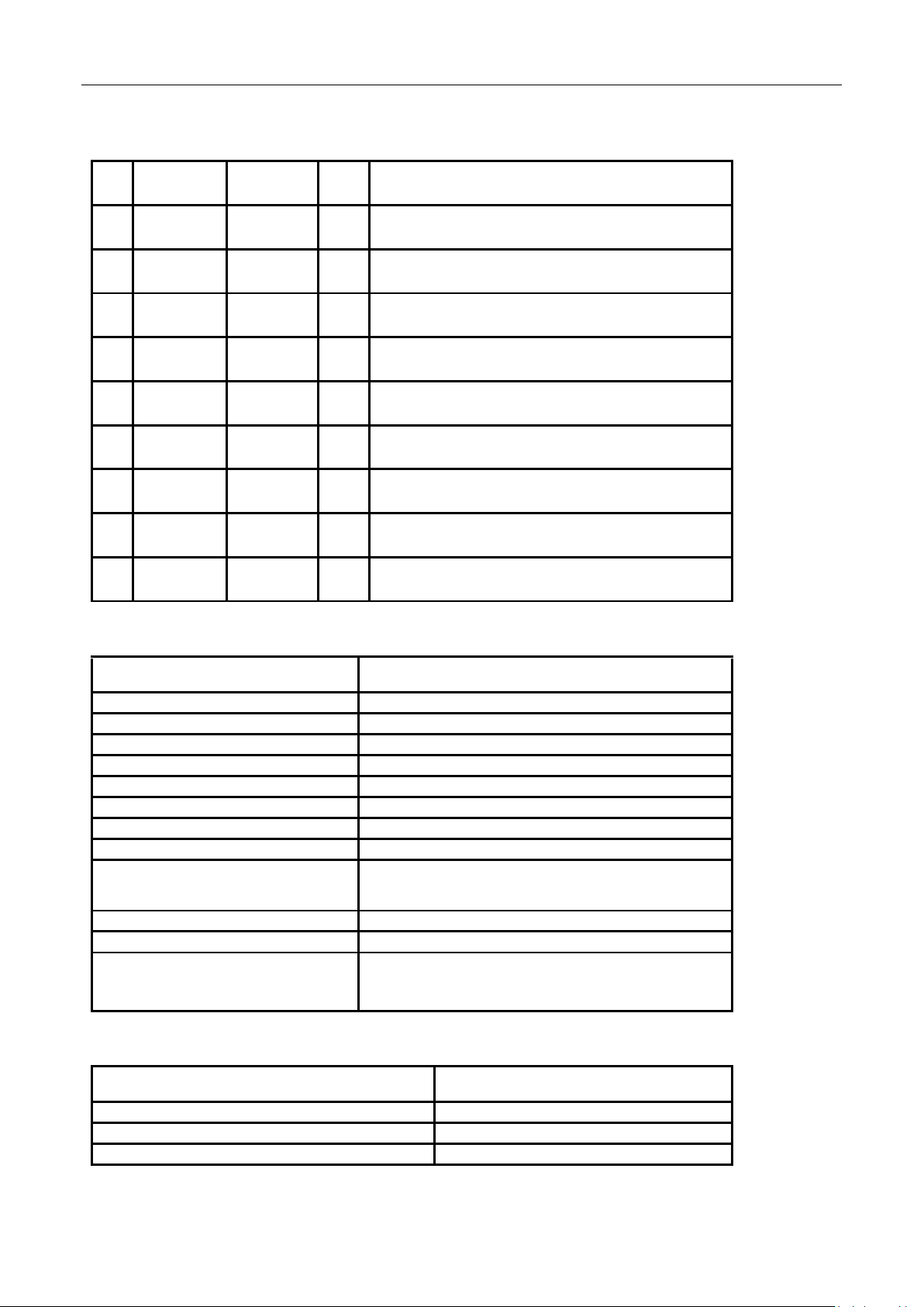
5.Pins Description
Pin
NAME
Inter
face
I/O
Description
1
VDD
Power
I
DC 3.3V input, Max 3.6V, Min 3.0V
2
GND
Ground
-
Ground
3 P0_W
PWM0
I/O
PWM0
4
P0_R
PWM1
I/O
PWM1
5
P0_G
PWM2
I/O
PWM2
6
P0_B
PWM3
I/O
PWM3
7
ADC
ADC
ADC
8
UART-RX
UART-RX
UART-RX
9
UART-TX
UART-TX
UART-TX
6.Electronic Specification
Item
Specification
RF Transmitting Power Level
+10 dBm Max
RF Receiver Sensitivity
-96 dBm at 1Mbps
Flash
512kb
Antenna
Printed PCB Antenna 1 dBi Gain
Linking Distance
At least 30 M
RAM
64KB
Data Rate
125 kbps,250 kbps, 500 kbps, 1 Mbps, 2 Mbps
Operation Voltage
3.0V to 3.6V
Operation Temperature
ET Version: -40℃ ~ +85℃,
AT version: ‐40℃~+125℃
Security
128 Bit AES encryption
Interface
PWM, UART, I2C,GPIO
EMC
Europe: ETSI EN 300 328 and EN 300 440 Class 2
USA: FCC CFR47 Part 15
Japan: ARIB STD-T66
7.Power Consumption
Operation Mode
Consumption
Operation (TX/RX) 0dBm
RX:5.3mA ,TX:4.8mA
Standby (Deep Sleep) depend on firmware
0.4uA (optional by firmware)
Page 8

8
8.Reflow Profile
9.Application Design Note
To Be Discussed
10.Antenna Design
Influence of GND on Antenna
a) The GND interrupts the emission of antenna but is essential.
b) RF vertical GND is important in antenna design.
c) Normally, the emission rate is improved as more GND is secured and edged GND of antenna is cut.
 Loading...