

Page 1
Installation Instructions for
Huntley 1, 2, 3, and 4 Light Vanity Strip
Wall
GP I :ENERAL RODUCT NFORMATION
V 4400_S
V 44001, V 44002,SS
V 44003 V 44004_SS
1.1
This product is listed by one of the following
“ ationally ecognized esting aboratory”NR TL
This product is suitable for damp locations.
This product may be dimmed with a standard incandescent dimmer.
This instruction shows a typical installation.
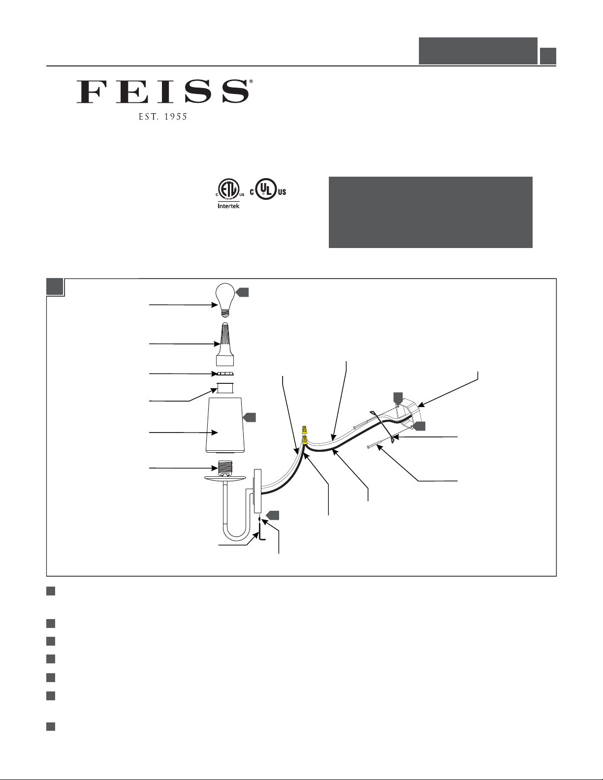
1A
LAMP
SHADE TOOL
COLLAR NUT
SPACER
SHADE
SOCKET
7
WHITE WIRE
6
5
CAUTION - RISK OF FIRE
This product must be installed in accordance with
the applicable installation code by a person familiar
with the construction and operation of the product
and the hazards involved.
Use minimum 90°c supply conductors.
NEUTRAL WIRE
ELECTRICAL BOX
1
1
MOUNTING
PLATE
MOUNTING
PLATE SCREW
HOT WIRE
BLACK WIRE
ALLEN WRENCH
FIXTURE SCREW
1
Secure the mounting plate to the electrical box with the two provided mounting plate screws (install anchors provided
with larger models for additional support).
Connect the fixture ground wire to a suitable ground in accordance to local electrical codes.
2
Connect the white fixture wire to the neutral power line wire with a wire nut.
3
4
Connect the black fixture wire to the hot power line wire with a wire nut.
5
Mount the fixture base onto the mounting plate and secure it with the fixture screws.
Place the shade and spacer over the socket, then secure them in place by tightening the collar nut using the shade tool;
6
repeat for remaining sockets.
7
Screw the lamp(s) into the socket(s). Refer to the label on the lamp socket for Max Wattage information.
1
Page 2
ATTENTION : RISQUE D'INCENDIE
Ce produit doit être installé conformément au code
d'installation en vigueur par une personne familière avec
la construction et l'exploitation du produit et les risques
qu'il entraîne.
Utiliser les conducteurs d'alimentation
supérieure à 90° c.
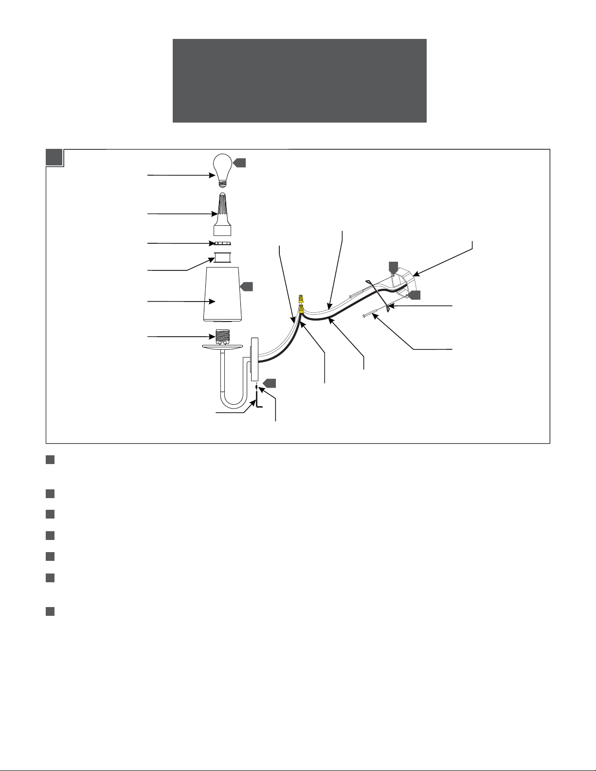
1A
AMPOULE
OUTIL D’ABAT-JOUR
ECROU À COLLIER
ESPACEUR
ABAT-JOUR
DOUILLE
CLÉ ALLEN
7
FIL BLANC
6
5
VIS DE LUMINAIRE
FIL NEUTRE
BOÎTE ÉLECTRIQUE
1
1
PLAQUE DE
MONTAGE
VIS DE
MONTAGE
FIL CHAUD
FIL NOIR
1
Fixez la plaque de montage à la boîte électrique avec les deux vis de montage (installer les ancrages fournis avec des
modèles plus grands pour un soutien supplémentaire).
2
Connectez le fil de terre du luminaire à un terrain approprié conformément aux codes électriques locaux.
3
Connectez le fil blanc du luminaire au fil de ligne à neutre avec un écrou de fil.
4
Connectez le fil noir du luminaire au fil ligne électrique chaud avec un serre-fils.
5
Montez l'base du luminaire sur la plaque de montage et le fixer avec les vis de fixation.
6
Placez l'abat-jour et espaceur dans le douille et fixer en place pour serrant l'écrou à collier avec l’outil de l’abat-jour ;
répétez pour les douilles restants.
7
Vissez l'ampoules dans les douilles. Lire l'étiquette sur la douille de lampe pour informations Max Wattage.
2
Page 3

PRECAUCIÓN: RIESGO DE INCENDIO
Este producto debe instalarse de acuerdo con el
código de instalación aplicable por una persona
familiarizada con la construcción y operación del
producto y los riesgos que conllevan.
Utilizar conductores de suministro
mínimo 90° c.
1A
BOMBILLA
HERRAMIENTA
DE LA PANTALLA
TUERCA DE COLLAR
ESPACIADOR
PANTALLA
ENCHUFE
LLAVE DE ALLEN
7
CABLE BLANCO
6
TORNILLO DE
LA LÁMPARA
CABLE NEUTRO
CAJA ELÉCTRICA
1
1
5
CABLE NEGRO
CABLE CALIENTE
PLACE DE
MONTAJE
TORNILLO
DE MONTAJE
1
Fije la placa de montaje a la caja eléctrica con los dos tornillos de la placa de montaje proporcionado (instale los anclajes
suministrados con los modelos más grandes de apoyo adicional).
2
Conecte el cable de tierra a una tierra artefacto adecuado de acuerdo a los códigos eléctricos locales.
3
Conecte el cable blanco de la lámpara al cable de energía de la línea neutral con un tapón de alambre.
4
Conecte el cable negro de la lámpara al cable de alimentación de línea caliente con un tapón de alambre.
5
Monte el base de la lámpara en la placa de montaje y fíjela con los tornillos de la lámpara.
6
Coloque la pantalla y el espaciador, luego asegúrelos apretando la tuerca de collar con la herramienta de la pantalla ;
repita para lost enchufes restantes.
7
Enrosque la bombilla en el enchufe. Consulte la etiqueta en el zócalo de la lámpara para obtener información de Max
Wattage.
3
Page 4

SAVETHESE INSTRUCTIONS!
555 Theodore Fremd Ave Suite B101 Rye, NY 10580
800.969.3347
www.Feiss.com
© 2014 Feiss.All rights reserved.The "Feiss" graphic is a
registered trademark of Feiss. Feiss reserves the right to
change specifications for product improvements without notification.
A Generation Brands Company
4
 Loading...