

Page 1
Installation Instructions for
P1304-P1305
Freemont 1 Light Pendant
Pendant
GP I :ENERAL RODUCT NFORMATION
This product is listed by one of the following
“ ationally ecognized esting aboratory”NR TL
This product is suitable for dry locations only.
This product may be dimmed with a standard incandescent dimmer.
This instruction shows a typical installation.
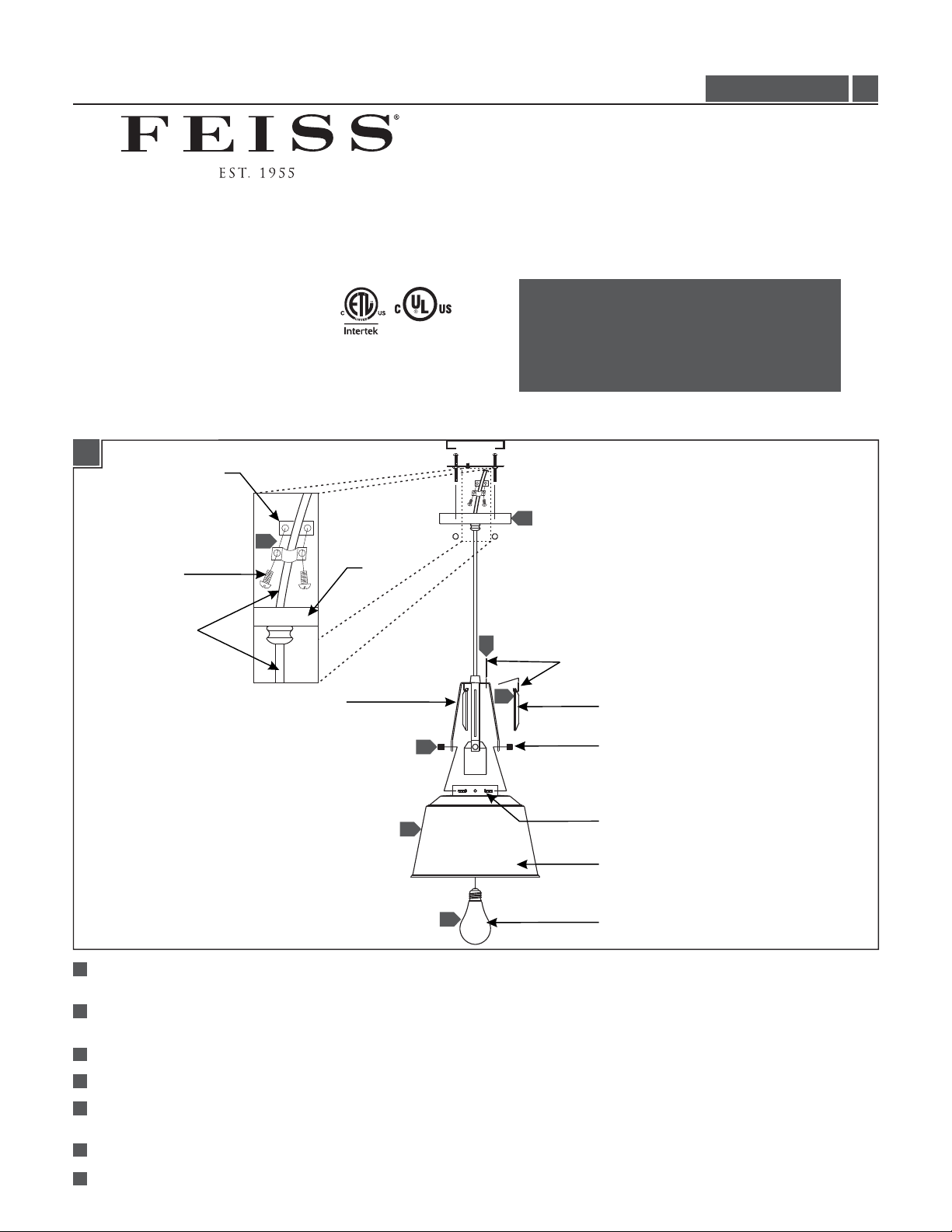
1A
CORD CLIP
4
P1304, P1305_
CAUTION - RISK OF FIRE
This product must be installed in accordance with
the applicable installation code by a person familiar
with the construction and operation of the product
and the hazards involved.
Use minimum 90°c supply conductors.
6
1.0
CLIP SCREW
CORD
FRAME
1
Align the shade with the frame, then insert the shade screws through the shade and the frame from the inside and secure them in
place by tightening with the knurled nuts.
2
Insert a bendable pin through the top of the frame and a decorative piece, then bend the pin into a hook like shape as shown on
drawing in order to securely hang the decorative piece; repeat for remaining decorative pieces.
3
Determine the wanted height of the fixture by feeding the cord through the canopy and moving the cord up or down.
4
Place the cord in between the two cord clips and secure it in place using the clip screws.
5
Trim the cord leaving enough for electrical connections. From the end of the cord, strip the insulation 4” and then strip the end of
the wires. Note: Make sure not to nick the inner wires.
6
Follow enclosed supplement installation instructions for electrical and fixture installation onto house outlet box.
7
Screw the lamp into the socket. Refer to the label on the lamp socket for Max Wattage information.
CANOPY
2
BENDABLE PIN
2
1
1
7
DECORATIVE PIECE
KNURLED NUT
SHADE SCREW
SHADE
LAMP
1
Page 2
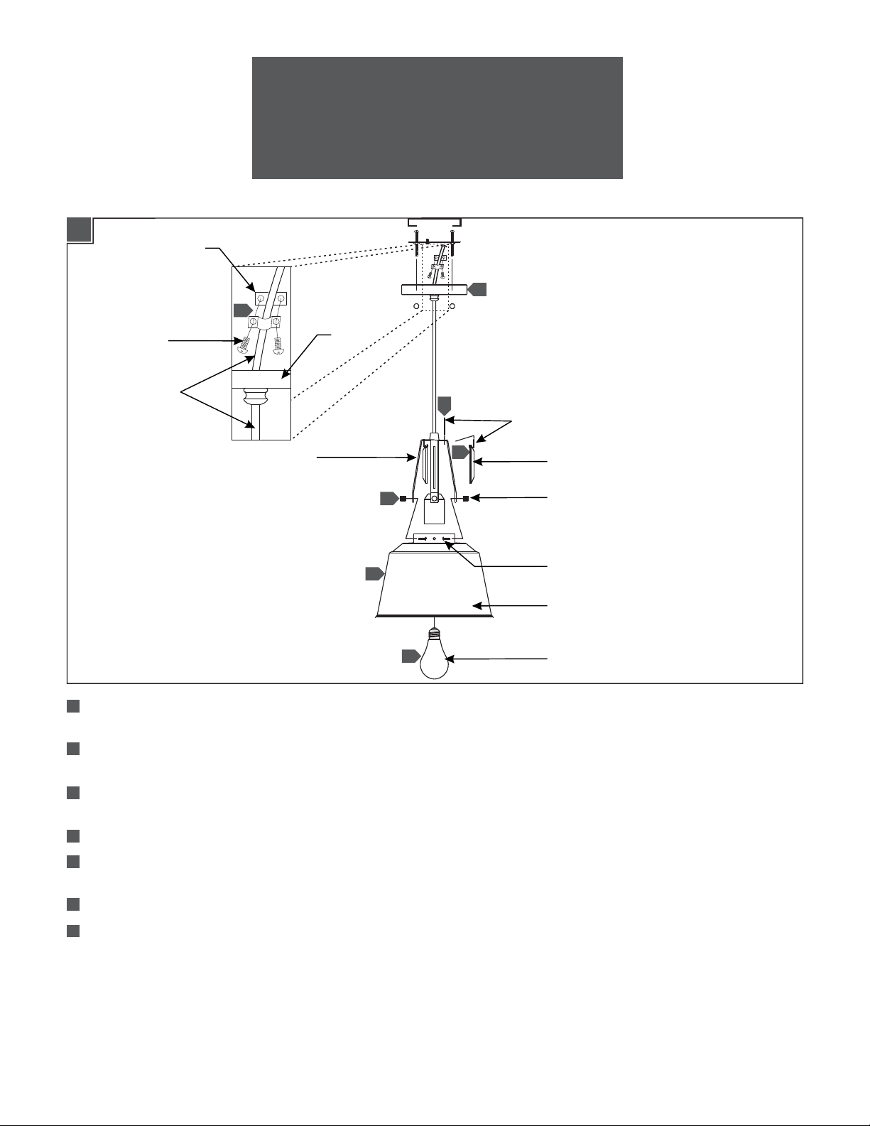
1A
ATTENTION : RISQUE D'INCENDIE
Ce produit doit être installé conformément au code
d'installation en vigueur par une personne familière avec
la construction et l'exploitation du produit et les risques
qu'il entraîne.
Utiliser les conducteurs d'alimentation
supérieure à 90° c.
PINCE DE
LE CORDON
6
4
VIS DE LA PINCE
CORDON
CADRE
1
Aligner l'abat-jour avec le châssis, puis insérez les vis d'abat-jour dans l'abat-jour et le cadre de l'intérieur et fixez-les en place
DAIS
2
BROCHE PLIABLE
2
1
1
7
PIÈCE DÉCORATIVE
ÉCROU MOLETÉ
VIS DE ABAT-JOUR
ABAT-JOUR
AMPOULE
en serrant l'écrous moleté.
2
Introduire une broche pliable dans le haut du cadre et une pièce décorative, puis plier la broche un crochet comme forme,
comme indiqué sur le dessin pour accrocher solidement la pièce décorative ; Répétez pour les autres pièces décoratives.
3
Déterminer la hauteur voulue de le luminaire en insérant le cordon à travers le dais et en déplaçant la corde vers le haut ou
vers le bas.
4
Placez le cordon entre les deux pince de cordon et fixez-le à l'aide des vis de la pince.
5
Coupez le cordon laissant assez pour le branchement électrique. Dès la fin du cordon, la dénuder 4 "et puis Dénudez
l'extrémité des fils. Remarque : Veillez à ne pas nick les fils internes.
6
Reportez-vous aux instructions pour supplément clos électrique et installation de luminaire sur boîte de sortie de maison
7
Vissez le ampoule dans le douille. Reportez-vous à l'étiquette sur la douille de lampe Puissance max pour plus d'informations.
2
Page 3

1A
PRECAUCIÓN: RIESGO DE INCENDIO
Este producto debe instalarse de acuerdo con el
código de instalación aplicable por una persona
familiarizada con la construcción y operación del
producto y los riesgos que conllevan.
Utilizar conductores de suministro
mínimo 90° c.
PINZA DEL
CABLE
6
4
TORNILLO DE
LA PINZA
CABLE
MARCO
1
Alinee la pantalla con el marco, luego inserte los tornillos de la pantalla a través de la pantalla y el marco desde el interior y
DOSEL
2
PIN FLEXIBLE
2
1
1
7
PIEZA DECORATIVA
TUERCA MOLETEADA
TORNILLO DE LA PANTALLA
PANTALLA
BOMBILLA
fíjelos en su lugar apretando las tuercas moleteadas.
2
Inserte una pin flexible en la parte superior del marco y una pieza decorativa, y doblar el pin en un gancho como forma como
se muestra en el dibujo para poder estar firmemente la pieza decorativa; Repita para piezas decorativas restantes.
3
Determine la altura deseada de la lámpara alimentando el cable a través del dosel y moviendo el cable hacia arriba o hacia
abajo.
4
Coloque el cable entre los dos pinzas y asegúrelo en su lugar utilizando los tornillos de la pinza.
5
Recortar el cable dejando suficiente para las conexiones eléctricas. Desde el extremo del cable, pelar el aislamiento de 4 "y
luego el extremo de los hilos. Nota: Asegúrese de que no a nick los alambres internos.
6
Siga las instrucciones de Instalación incluido suplemento para eléctricos e instalación de la lámpara en la caja de enchufe de
casa.
7
Enrosque la bombilla en el enchufe. Consulte la etiqueta en el enchufe de la lámpara para obtener información de Max
Wattage.
3
Page 4

SAVETHESE INSTRUCTIONS!
555 Theodore Fremd Ave Suite B101 Rye, NY 10580
800.969.3347
www.Feiss.com
© 2014 Feiss.All rights reserved.The "Feiss" graphic is a
registered trademark of Feiss. Feiss reserves the right to
change specifications for product improvements without notification.
A Generation Brands Company
4
 Loading...