

Page 1
Assembly Instructions For
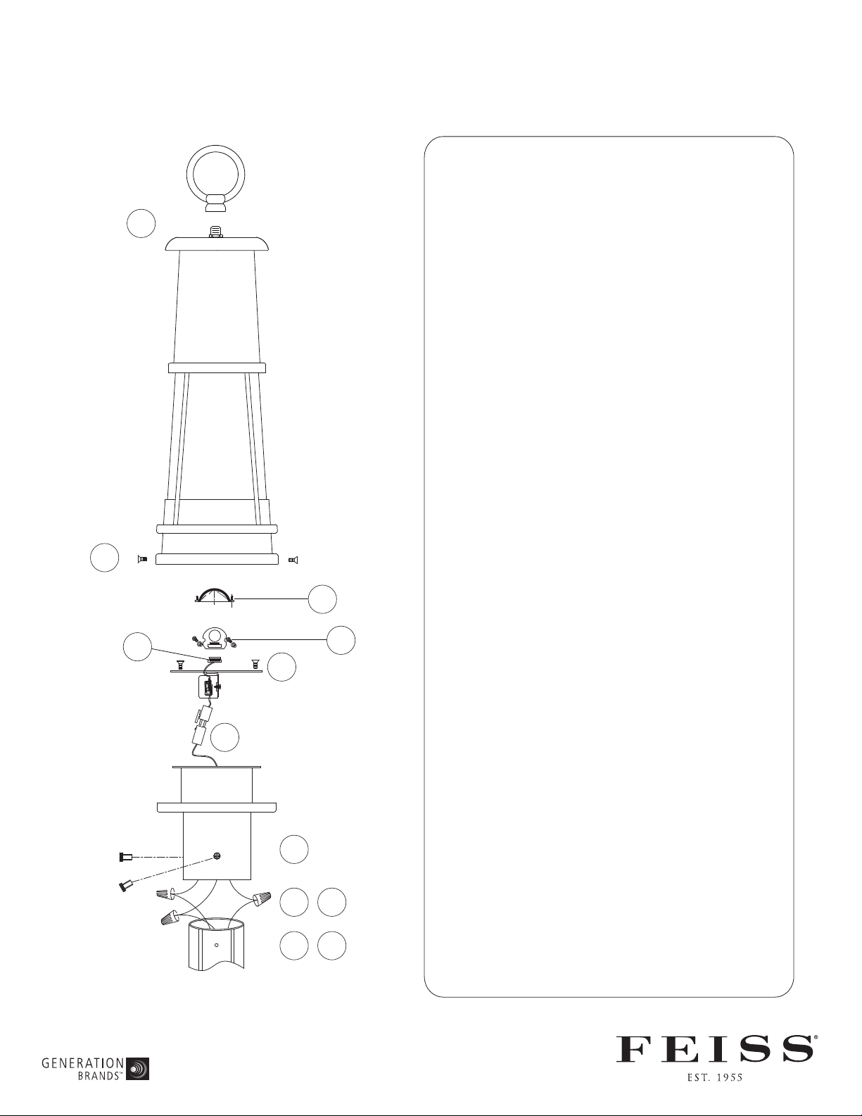
OL8207
TURN OFF THE POWER AT THE MAIN FUSE OR
1
4
Carefully unpack and identify all parts before
assembly. Bulb not included.
1.
Install the fixture loop onto the top of the
fixture.
2. Electrical installation onto post (not supplied): If
you are replacing an existing fixture, disconnect
and remove the old fixture.
A) Slip post cup over post. Mark position of holes
in post cup on post.
B) Remove post cup and expose the supply wiring
from above post. Drill and tap a screw hole for
the provided screw.
C) Connect white fixture wire to white supply wire
from post with wire connector. Connect black
fixture wire to black supply wire from post with
wire connector.
NOTE: Black wire from post may be red, round
and smooth and/or have copper conductor. White
wire from post may be square and ridged and/or
have a silver conductor.
(E) 12/11
IMPORTANT
CIRCUIT BREAKER BOX
BEFORE STARTING INSTALLATION
3D
3E
3A
2F
2C2A2D
3B
2B
3C
D) Connect fixture ground wire (without plastic
insulation) to ground wire from post (usually with
green insulation) with wire connector.
IMPORTANT: Never connect ground wire to black
or white supply wires.
E) Tuck all wires inside of post.
F) Slip post cup onto post. Align holes in post cup
with holes in post. Secure them together by
fastening with machine screws (enclosed).
3.
LED bulb and driver replacement:
A. Unscrew the 2 screws from the LED panel
and carefully pull down the LED panel.
B. Unscrew the 3 screws for the lens and
remove the lens.
C. Unscrew the 2 screws from the LED bulb
housing and remove LED bulb.
D. Unplug the connection marked 3D and
replace with a new LED bulb.
E. Unplug the connections marked 3D & 3E
and replace with a new driver.
4. Install the bottom cover onto the main frame and
fasten with screws.
 Loading...