

Page 1
Installation Instructions for
OL13300-OL13301-OL13302
Hodges Outdoor Wall
Outdoor
GP I :ENERAL RODUCT NFORMATION
These fixtures are intended to be installed utilizing compliant junctionNEC
boxes.
This product is safety listed for wet locations.
Incandescent lamps may be dimmed with a standard incandescent dimmer.
LED LEDlamps may be dimmed with a dimmer. Consult lamp manufacturer for
additional information.
This instruction shows a typical installation.
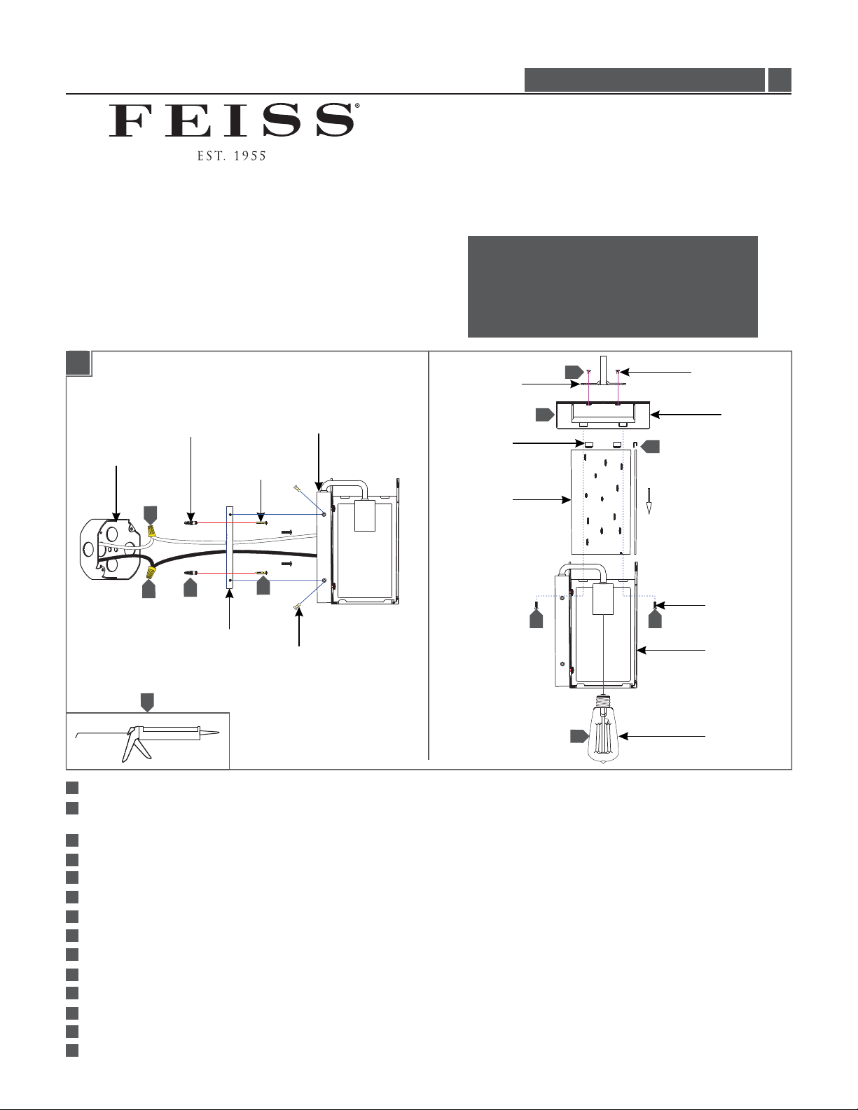
1A
FIXTURE
BASE
JUNCTION BOX
ANCHOR
ANCHOR
SCREW
O 13300, O 13301, OL13302LL
CAUTION RISK OF FIRE-
This product must be installed in accordance with
the applicable installation code by a person familiar
with the construction and operation of the product
and the hazards involved.
Use minimum 90°c supply conductors.
FIXTURE LOOP
CLIP
12
11
10
1.0
FIXTURE
LOOP SCREW
COVER
7
3
8
MOUNTING
PLATE
14
1
For Models OL13301 and OL13302 Only: Temporarily install the mounting plate to the junction box.
2
For Models OL13301 and OL13302 Only: Mark the anchor hole locations on the mounting plate and remove the mounting
5
FIXTURE
SCREW
GLASS PANEL
11
13
11
COVER
SCREW
FIXTURE
LAMP
plate.
For Models OL13301 and OL13302 Only: Drill appropriate size holes at the marked locations and install the anchors.
3
Secure the mounting plate to the junction box.
4
5
For Models OL13301 and OL13302 Only: Screw the anchor screws into the anchors.
6
Connect the fixture to a suitable ground in accordance with local electrical codes.
7
Connect the white fixture wire to the neutral power line wire with a wire nut.
8
Connect the black fixture wire to the hot power line wire with a wire nut.
9
Mount the fixture base onto the mounting plate and secure it with the fixture screws.
Insert the glass panels into the fixture and secure them in place using the clips.
10
11
Install the cover on top of the fixture and secure it using the cover screws.
Install the fixture loop to the top of the cover and secure it in place with the fixture loop screws.
12
13
Screw the lamp into the socket. Refer to the label on the socket for Max Wattage Information.
14
For wet locations, caulk around the base of the fixture with waterproof construction sealant.
1
Page 2
ATTENTION RISQUE INCENDIE:D'
Ce produit doit être installé conformément au code
d'installation en vigueur par une personne familière avec
la construction et l'exploitation du produit et les risques
qu'il entraîne.
Utiliser les conducteurs d'alimentation
supérieure à 90° c.
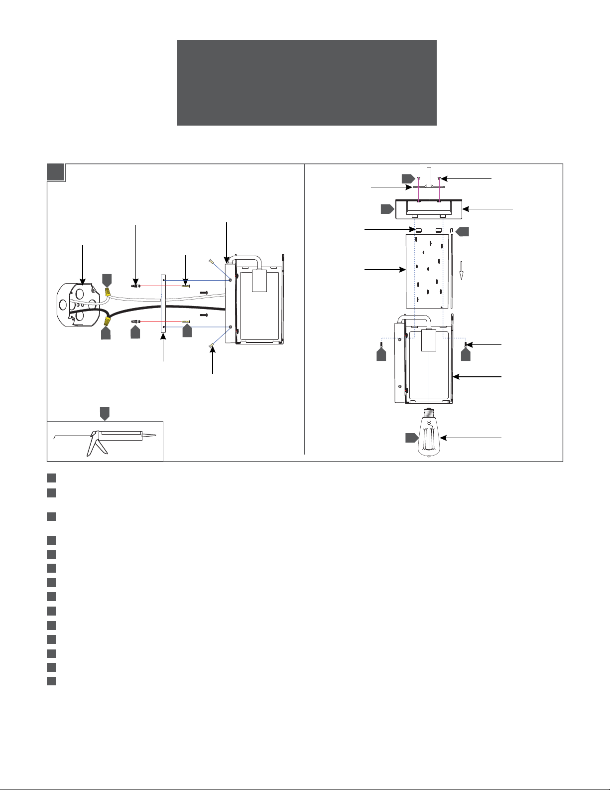
1A
BOÎTE DE
JONCTION
14
BOUCLE DE
LUMINAIRE
BASE DE
ANCRE
VIS DE
ANCRE
7
3
8
PLAQUE DE
MONTAGE
LUMINAIRE
AGRAFE
PANNEAU
DE VERRE
5
VIS DE
LUMINAIRE
12
11
10
11 11
13
VIS DE BOUCLE
DE LUMINAIRE
COUVERCLE
VIS DE
COUVERCLE
LUMINAIRE
AMPOULE
1
Pour Modèles OL13301 et OL13302 Seulement: Installez temporairement la plaque de montage à la boîte de jonction.
Pour Modèles OL13301 et OL13302 Seulement: Marquez l'emplacement des trous d'ancre sur la plaque de montage et
2
retirer la plaque de montage.
3
Pour Modèles OL13301 et OL13302 Seulement: Percer des trous de taille appropriée aux emplacements marqués et
installer les ancres.
4
Fixer la plaque de montage à la boîte de jonction.
5
Pour Modèles OL13301 et OL13302 Seulement: Visser les vis d'ancre dans l’ancres.
6
Connectez le luminaire à un terrain approprié conformément aux codes électriques locaux.
7
Connectez le fil blanc de luminaire au fil de la ligne d'alimentation neutre avec un écrou de fil.
8
Connectez le fil noir de luminaire au fil de la ligne d'alimentation chaude avec un écrou de fil.
Montez la base de luminaire sur la plaque de montage et le fixer avec les vis de luminaire.
9
Insérez les panneaux de verre dans la luminaire et les fixer en place à l'aide des agrafes.
10
Installer le couvercle sur le dessus de luminaire et le fixer en utilisant les vis de couvercle.
11
Installez la boucle de luminaire à la partie supérieure de couvercle et le fixer en place avec les vis de la boucle de luminaire.
12
Visser l’ampoule dans la douille. Reportez-vous à l'étiquette sur la prise pour Max Wattage information.
13
14
Pour les endroits humides, calfeutrez autour de la base de le luminaire avec une construction étanche étanché
2
Page 3

PRECAUCIÓN RIESGO DE INCENDIO:
Este producto debe instalarse de acuerdo con el
código de instalación aplicable por una persona
familiarizada con la construcción y operación del
producto y los riesgos que conllevan.
Utilizar conductores de suministro
mínimo 90° c.
1A
CAJA DE
JUNCTURA
14
7
8
ANCLAJE
3
TORNILLO
DE ANCLAJE
PLACA DE
MONTAJE
BASE DE
LA LÁMPARA
5
TORNILLO DE
LA LÁMPARA
BUCLE DE
LAMPARA
BROCHE
PANELE DE
VIDRIO
12
11
10
11 11
13
TORNILLO DEL BUCLE
DE LAMPARA
TORNILLO DE
LA CUBIERTA
CUBIERTA
LAMPARA
BOMBILLA
1
Para Modelos OL13301 y OL13302 Solamente: Instalar temporalmente la placa de montaje a la caja de junctura.
Para Modelos OL13301 y OL13302 Solamente: Marque la ubicación de los orificios de anclaje en la placa de montaje y
2
retire la placa de montaje.
3
Para Modelos OL13301 y OL13302 Solamente: Perforar agujeros del tamaño adecuado en los lugares marcados y
instalar los anclajes.
Fije la placa de montaje a la caja de junctura.
4
5
Para Modelos OL13301 y OL13302 Solamente: Atornille los tornillos de anclaje en los anclajes.
6
Conecte la lámpara a una tierra adecuada, de acuerdo con los códigos eléctricos locales.
7
Conecte el cable blanco de la lámpara al cable de línea de energía neutra con una tuerca para cable.
8
Conecte el cable negro de la lámpara al cable de línea eléctrica caliente con una tuerca para cable.
9
Monte la base de lámpara sobre la placa de montaje y fijarlo con los tornillos de lámpara.
10
Inserte los paneles de vidrio en la lámpara y fijarlos en su lugar con los broches.
11
Instale la cubierta en la parte superior de la lámpara y fijarlo usando los tornillos de la cubierta.
12
Instalar el bucle de la lámpara de la parte superior de la cubierta y fijarla en su lugar con los tornillos de la lámpara de
bucle.
13
Atornille la bombilla en el enchufe. Consulte la etiqueta en la toma de Max Información de Potencia.
14
Para lugares húmedos, calafatear alrededor de la base de la lámpara con sellador de construcción resistente al agua.
3
Page 4

SAVE THESE INSTRUCTIONS!
7400 Linder Ave, Skokie, 160077IL
800.969.3347
www.Feiss.com
© 2017 Feiss.All rights reserved.The "Feiss" graphic is a
registered trademark of Feiss. Feiss reserves the right to
change specifications for product improvements without notification.
A Generation Brands Company
4
 Loading...