

Page 1
Assembly Instructions For
FM335
TURN OFF THE POWER AT THE MAIN FUSE OR
1
Carefully unpack and identify all parts before assembly. Bulbs
2
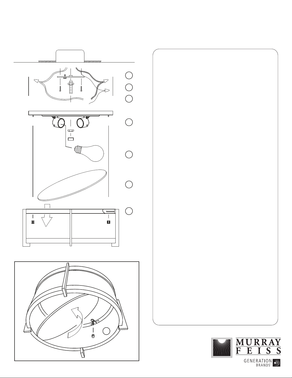
1. Attach mounting bar securely to ceiling junction box with
3
Note: mounting bar should be installed with "GND" imprint
4
5
6A
6B
2. A. Fasten one hex nut about 3/4" (19 mm) down from one
B. Then screw same end of threaded pipe into center hole in
C. At this point test install the pan onto ceiling through this
3. A. Spread the electrical wires so that the black wires are on
B. Electrical connections:
Connect the white wire from the fixture to the white wire of
NOTE: Black outlet box wire may be red, round & smooth
(E) 11/09
IMPORTANT
CIRCUIT BREAKER BOX
BEFORE STARTING INSTALLATION
not included.
two machine screws (supplied with junction box) through
slot at each end of mounting bar.
and/or two dimples facing down.
end of threaded pipe.
mounting bar.
threaded pipe and make certain 3/8" (10 mm) of pipe
protrude below. If not, then adjust the threaded pipe location
by screwing up or down accordingly. Once correct threaded
pipe location has been adjusted, remove pan and tighten hex
nut against mounting bar. Make certain not to spin threaded
pipe during tightening.
one side of the outlet box and the white wires are on the
other side.
the outlet box. Connect the black wire from the fixture to
the black wire of the outlet box.
and/or have copper conductor. White outlet box wire may be
square & ridged and/or have a silver conductor.
6C
C. Grounding Connection:
Connect fixture ground wire (without insulation) to ground
wire from outlet box (usually with green insulation) with
wire connector (not provided).
IMPORTANT: Never connect ground wire to black or white
power supply wires.
4. Place pan through threaded pipe so that it sits flush against
ceiling. Be sure all wires are inside pan. Secure pan to ceiling
by fastening with a hex nut. Then fasten cap nut.
5. Install bulb (not included). See relamping label located at
socket area for type and maximum allowed wattage.
6. A. Slip glass plate inside of main frame and allow to sit at
bottom.
B. Slip and hold main frame against the installed pan, making
certain the three threaded screws in pan are aligned with the
three tabs inside of main frame.
C. While firmly holding onto main frame, lift and tilt glass
plate toward one side then insert hand to fasten with three
cap nuts. See fig. 2.
Fig. 2
 Loading...