

Page 1
Installation Instructions for
P1294-F2931-6
Adams 3 and 4 Light Chandelier
Chandelier
GP I :ENERAL RODUCT NFORMATION
This product is listed by one of the following
“ ationally ecognized esting aboratory”NR TL
This product is suitable for dry locations only.
This product may be dimmed with a standard incandescent dimmer.
This instruction shows a typical installation.
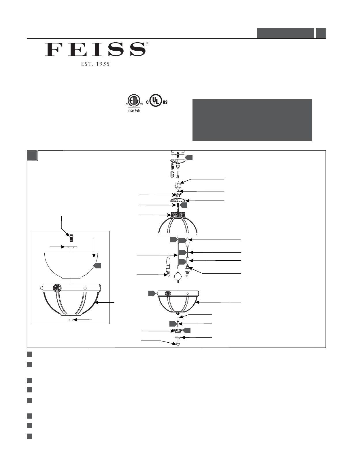
1A
UPPER SPACER
UPPER NIPPLE
SHADE NIPPLE
UPPER ASSEMBLY
P1294, F2931/6_
CAUTION - RISK OF FIRE
This product must be installed in accordance with
the applicable installation code by a person familiar
with the construction and operation of the product
and the hazards involved.
Use minimum 90°c supply conductors.
8
FIXTURE LOOP
UPPER WASHER
2
UPPER CUP
1.0
SHADE
SPACER
STEM
5
FIXTURE
7
FRAME
NUT
LOWER CUP
FINIAL
1
Screw the stem to the fixture, then screw the stem to the upper assembly.
Screw the upper nipple to the top of the upper assembly, then place the upper cup, spacer, and washer onto the threaded nipple
2
and secure them together by tightening with the fixture loop.
3
Install the candle tubes by slipping them through the sockets, then place the candle followers on top of the candle tubes.
4
Screw the lamps into the sockets. Refer to the label on the lamp socket for Max Wattage information.
Place the shade inside of the frame, then place the spacer and the shade nipple into the shade and secure them together by
5
tightening the nut.
6
Place the lower washer onto the bottom of the fixture and screw the lower nipple to the bottom of the fixture.
7
Place the lower assembly, lower cup, and lower spacer over the lower nipple and secure them in place by tightening the finial.
8
Follow enclosed supplement installation instructions for electrical and fixture installation onto house outlet box.
1
4
3
3
LOWER WASHER
6
7
LOWER NIPPLE
LOWER SPACER
LAMP
CANDLE FOLLOWER
CANDLE TUBE
SOCKET
LOWER ASSEMBLY
1
Page 2
ATTENTION : RISQUE D'INCENDIE
Ce produit doit être installé conformément au code
d'installation en vigueur par une personne familière avec
la construction et l'exploitation du produit et les risques
qu'il entraîne.
Utiliser les conducteurs d'alimentation
supérieure à 90° c.
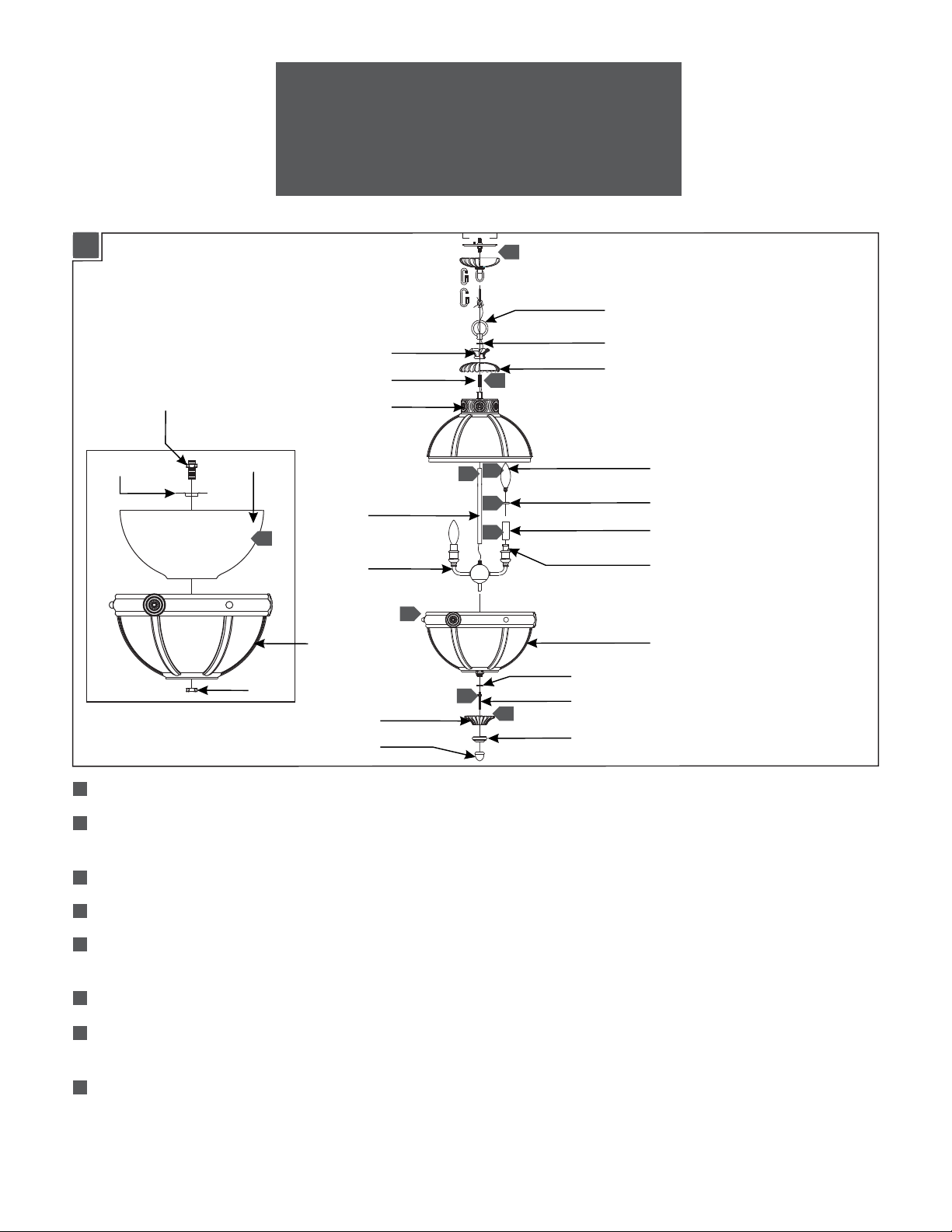
1A
ESPACEUR
ATTACHE
D’ABAT-JOUR
ESPACEUR SUPÉRIEURE
ATTACHE SUPÉRIEURE
ASSEMBLEÉ SUPÉRIEURE
ABAT-JOUR
5
LUMINAIRE
CADRE
ECROU
COUPE INFÉRIEURE
TIGE
FLEURON
8
BUCLE DE LUMINAIRE
RONDELLE SUPÉRIEURE
2
4
1
3
3
7
6
7
COUPE SUPÉRIEURE
AMPOULE
SUIVEUR DE LA BOUGIE
TUBE BOUGIE
DOUILLE
ASSEMBLEÉ INFÉRIEURE
RONDELLE INFÉRIEURE
ATTACHE INFÉRIEURE
ESPACEUR INFÉRIEURE
1
Vissez la tige sur le luminaire, puis vissez la tige à la assemblée supérieure,.
2
Vissez la attache supérieure vers le haut de la assemblée supérieur, puis placez la coupe supérieure, espaceur supérieure et
rondelle sur le attache fileté et fixez-les ensemble en serrant avec la boucle du luminaire.
3
Installez le tubes de bougie en les glissant à travers le douille.
4
Vissez les ampoules dans les douilles. Lire l'étiquette sur la douille de lampe pour informations Max Wattage.
5
Placer l'abat-jour à l'intérieur de le cadre, puis placer le espaceur et le attache de l'abat-jour dans l'abat-jour et fixez-les
ensemble en serrant l'écrou.
6
Placez la rondelle inférieure sur la partie inférieure de le luminaire et vissez le attache inférieur vers le bas de le luminaire.
7
Placez la assembleé inférieure, coupe inférieur et espaceur inférieure sur le attache inférieur et fixez-les en place en serrant
le fleuron.
Suivez supplément ci-joint des instructions électriques et installation d'accessoires dans la boîte de prise de maison.
8
2
Page 3

PRECAUCIÓN: RIESGO DE INCENDIO
Este producto debe instalarse de acuerdo con el
código de instalación aplicable por una persona
familiarizada con la construcción y operación del
producto y los riesgos que conllevan.
Utilizar conductores de suministro
mínimo 90° c.
1A
ESPACIADOR
CONECTADOR
DE LA PANTALLA
ESPACIADOR SUPERIOR
CONECTADOR SUPERIOR
ASAMBLEA SUPERIOR
PANTALLA
5
LÁMPARA
MARCO
TUERCA
COPA INFERIOR
TALLO
FINIAL
8
BOUCLE DE LA LÁMPARA
ARANDELA SUPERIOR
2
4
1
3
3
7
6
7
COPA SUPERIOR
BOMBILLA
SEGUIDOR DE VELA
TUBO DE VELA
ENCHUFE
ASAMBLEA INFERIOR
ARANDELA INFERIOR
CONECTADOR INFERIOR
ESPACIADOR INFERIOR
1
Atornillar el tall y la lámpara, luego atornillar el tallo a la asamblea superior.
2
Atornillar la conectador superior a la parte superior de la asamblea superior, a continuación, coloque la copa superior,
espaciador superior y la arandela superior en el conectador roscado y fíjelos juntos apretando con el boucle de la lámpara.
3
Instale el tubo de vela deslizándolo a través de el enchufe.
4
Atornille la bombilla en el enchufe. Consulte la etiqueta en el zócalo de la lámpara para obtener información de Max
Wattage.
5
Coloque la pantalla dentro del marco, y luego coloque el espaciador y el conectador de la pantalla en la pantalla y fíjelos
juntos apretando la tuerca.
6
Coloque la arandela inferior en la parte inferior de la lámpara y atornillar la conectador inferior a la parte inferior de la
lámpara.
7
Coloque la asamblea inferior, copa inferior y espaciador inferior sobre el conectador inferior y fíjelos en su lugar apretando
el finial.
8
Siga las instrucciones de instalación incluido suplemento para eléctricos y instalación de la lámpara en caja de salida de la
casa.
3
Page 4

SAVETHESE INSTRUCTIONS!
555 Theodore Fremd Ave Suite B101 Rye, NY 10580
800.969.3347
www.Feiss.com
© 2014 Feiss.All rights reserved.The "Feiss" graphic is a
registered trademark of Feiss. Feiss reserves the right to
change specifications for product improvements without notification.
A Generation Brands Company
4
 Loading...