


RB50 Microscope User’s Manual
info@feinoptic.com
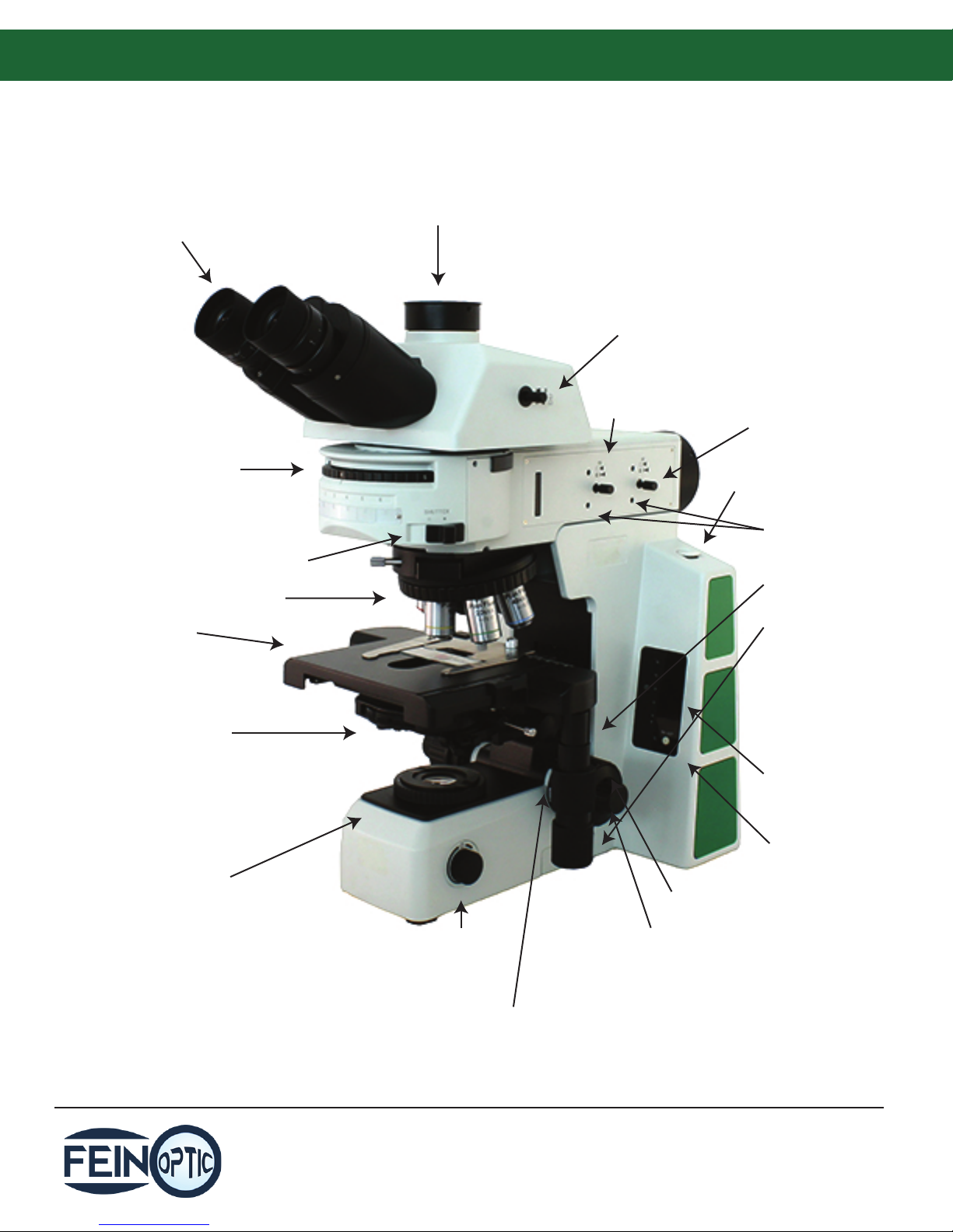
Microscope Components:
RB50 Fluorescence Microscope
Eyepieces
Filter Cube
Selector
Sextuple Nosepiece
Mechanical Stage
Shutter Lever
Trinocular Port
Beam Splitter
Field Diaphragm
Adjustment
Aperture Diaphragm
Adjustment
Hex Wrench
Diaphragm Centering
Screws
Y-Axis Knob
X-Axis Knob
Condenser
Illuminator
Light Rheostat
Adjustment
Knob
Focusing Tension
Page 1
Voltage Indicator
Reset Button
for Intensity
Coarse Focusing
Fine Focusing
Adjustment
info@feinoptic.com
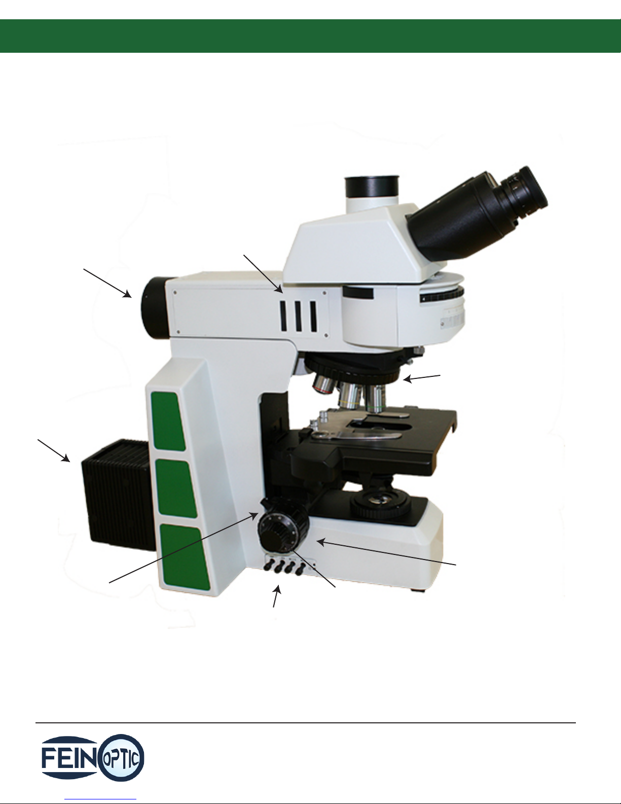
Microscope Components:
RB50 Fluorescence Microscope
Fluorescence Illuminator
Attachment
100w Halogen
Light Source
ND Filter Slots
Quintuple
Nosepiece
Coarse Adjustment
Limit Ring
Filter Levers
Page 2
Coarse Focus
Knob
Fine Focus
Knob
info@feinoptic.com

Binocular / Trinocular Microscope Assembly:
RB50 Microscope Assembly
RB50 Fluorescence Microscope Assembly
Page 3
info@feinoptic.com

Before Use:
Do not shake or drop the microscope.
Do not not expose the microscope to
direct sun, high temperatures, dust, or
damp environments. Use a at work
surface. Indoor operating temp
41°~104°F (5°~40°C), max relative
humidity of 80%.
When moving the microscope use both hands,
holding by the handle at the back (1) and the base
(2) as shown at right.
When working, the surface of the light source
will be warm. Make sure there is enough room
for the heat to dissipate around the light
source.
Set the power switch to o “O” before
replacing a bulb or fuse, and wait until the
lamp is cool. The power switch (3) is located on
the back of the base of the microscope.
Microscope uses 12V, 100W halogen bulb.
(Part# 12v100wH).
Voltage range of 100~240V is supported.
Additional transformer is not necessary. Use
only an outlet with voltage in this range and
use the power cord supplied with the
microscope.
Page 4
info@feinoptic.com

Maintenance:
Wipe lenses gently with a soft tissue. Carefully remove excess oil from the 100x immersion oil lens.
Wipe o ngerprints from lens surfaces with lens paper using a small amount of microscope cleaning
solution or a 3:7 mixture of alcohol and ether or dimethylbenzene. (Alcohol and ether are ammable,
do not place these chemicals near re and clean in a ventilated area.)
When cleaning other surfaces of the microscope use water only. A basic detergent can be used to
clean the surface if necessary, but ensure that all the detergent is removed from the frame with a
clean, damp cloth prior to drying the surface.
If the microscope becomes wet during use, power off the microscope and dry the microscope
thoroughly.
Do not disassemble the microscope.
After use, cover the microscope with a dust cover and power o the light.
Objectives:
RB50 Innity Corrected Objectives all have a parfocal distance of 45mm.
Recommended coverslip thickness is 0.17mm.
Objective Type
Plan Achromat
Plan Semi
Apochromat Fluor
Plan Phase
Contrast
Part # / Magnication
FPLN4 / 4x
FPLN10 / 10x
FPLN20 / 20x
FPLN40 / 40x
FPLN50 / 50x Oil
FPLN60 / 60x
FPLN100 / 100x Oil
SAPOFL4 / 4x
SAPOFL10 / 10x
SAPOFL20 / 20x
SAPOFL40 / 40x
SAPOFL100 / 100x Oil
FPL-PH10 / 10x
FPL-PH20 / 20x
FPL-PH40 / 40x
FPL-PH100 / 100x Oil
Numerical Aperture
0.10
0.25
0.40
0.65
0.95
0.85
1.25
0.13
0.30
0.50
0.75
1.28
0.25
0.40
0.65
1.25
Working Distance
11.9mm
12.1mm
1.5mm
0.36mm
0.19mm
0.3mm
0.18mm
18.5mm
10.6mm
2.33mm
0.6mm
0.21mm
12.1mm
1.5mm
0.36mm
0.18mm
Page 5
info@feinoptic.com
Step-by-Step Assembly:
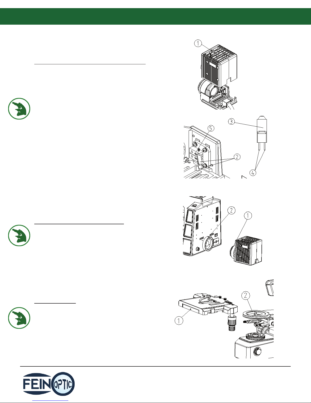
Light Source Assembly & Bulb Replacement:
Loosen the lock screw (1) completely with an M4
spanner and remove the cover.
Open the bulb lock (2).
Handle the bulb (3) with a clean glove or soft tissue
(do not touch the bulb with ngers).
Insert the bulb pins (4) into the bulb holder (5).
The bulb should be vertical after assembly.
If any ngerprints got on bulb, wipe clean with a
clean, soft cloth.
Replace bulb only with 12v, 100w halogen bulb
(part# 12v100wH).
Before replacing the bulb, make sure to unplug and
power o the microscope. Wait for the bulb housing
to cool o before opening.
Light Source Microscope Assembly:
Push the light source holder (1) into the body of the
microscope. Keep the light source horizontal in
relation to the microscope body and tighten the
screw (2).
Stage Assembly:
Loosen the set screw (1) on the stage.
Center the stage on the base, aligning the two “V”
notches on the bottom of stage and on the
condenser (2).
Tighten the set screw.
Page 6
info@feinoptic.com

Step-by-Step Assembly:
Condenser Assembly:
Rotate the coarse focusing knob (1) to raise the stage
to its highest setting.
Rotate the condenser height adjustment knob (2) to
lower the condenser bracket to its lowest setting.
Loosen the condenser set screw (3).
Swing out the front lens of the condenser with the
scale facing forward. Line up the condenser screw (4)
with the groove (5) of the condenser holder.
Tighten the condenser set screw (3) and raise the
condenser to the highest position with the
condenser height adjustment knob.
Nosepiece Assembly:
Loosen the set screw (1) on the microscope arm.
Line up the dovetail interface (2) of the nosepiece
with the dovetail groove on the microscope arm and
insert it into the body.
Tighten the set screw (1) on the microscope arm.
Head Assembly:
Loosen the head set screw (1) on the microscope
arm.
From a right angled position, insert the coattail
interface on the bottom of the head into the hole in
the middle of the arm. Keep the eyetubes inclined
forward.
Tighten the set screw (1) on the microscope arm.
Objective Assembly:
Rotate the coarse focusing knob to lower the stage.
Install the objectives (1) into the nosepiece from the
lowest magnication to the highest magnication in
a clockwise direction.
Search and focus for a sample starting with the
lowest objective (4x or 10x) when operating. Then
move up to a higher magnication.
Page 7
info@feinoptic.com

Step-by-Step Assembly:
Eyepiece Assembly:
Remove the cover from the eyetube (1). Insert the
eyepiece into the eyetube.
Match up the positioning screw (2) into the eyetube
groove (3) when inserting the eyepiece into the
eyetube.
Power Cord Connection:
Set the main switch to “O” (o) position.
Connect the lower light source plug (1) into the
socket (2) on the back of the microscope.
Insert one end of the power cord (3) into the power
socket (4). Plug in the microscope.
Use only the power cord supplied by Fein Optic.
Illumination:
Turn the main power switch to “--” on.
Adjust the light rheostat control (4) until the
illumination is comfortable for observation. Rotate
the light rheostat knob clockwise to raise the voltage
and brightness. Rotate counterclockwise to lower
the voltage and brightness.
Press the light intensity reset button (1) to reset the
light intensity to the preset position. Rotate the set
screw (2) with a small athead screwdriver to set the
light intensity. Rotating it clockwise will raise the
light intensity, counterclockwise will lower it.
Voltage indicator (3) shows voltage intensity.
Using bulbs in low voltage state will extend bulb life.
The rheostat knob will not work when the light
intensity button is pressed.
Microscope light intensity is pre-set to the best light
for photomicrography with a daylight-balanced
(LBD) lter.
Page 8
info@feinoptic.com

Step-by-Step Assembly:
Slide Placement:
Push the slide holder clamp (1) backwards.
Place the slide between the slide holder clamp (1)
and the slide holder (2) with the cover slip facing up.
Rotate the X-Axis knob (4) and the Y-Axis knob (3) to
position the slide in the center under the objective.
Beam Splitter:
When using the trinocular microscope, in order to
send light up to the camera (trinocular) port, pull the
beam splitter (1) out. When the beam splitter is
pushed in all the light will go to the eyepieces.
When it is pulled out part way light will go to the
camera and the eyepieces. And when it is pull out
100%, all light will go to the trinocular port.
Focusing Adjustment:
Place a slide on the stage. Move the 4x objective into
position.
Loosen the upper limit lever (1), then observe
through the right eyepiece. Rotate the coarse
focusing knob (2) until the image appears in the eld
of view, then lock the upper limit lever (1).
The upper limit lever can prevent the objective from
touching the slide when focusing.
The upper limit lever does not aect the ne focus
knob.
Rotate the ne focus knob (3) to obtain a clear
image.
When observing with the 4x or 10x objective, open
both the aperture diaphragm and eld iris
diaphragm to the maximum position and swing out
the front condenser lens.
Page 9
info@feinoptic.com

Step-by-Step Assembly:
Focus Tension Adjustment:
If the focus knob is very tight or the stage drifts after
being focused, the tension adjustment knob (1)
should be adjusted. Rotating the knob clockwise will
tighten the tension and rotating it counterclockwise
will loosen the tension of the focus knob.
Interpupillary Distance Adjustment:
When using both eyepieces for observation, hold the
base of the eyetubes and rotate the eyepieces
around the axis to adjust the interpupillary distance
until you see only one eld of view.
The mark on the left eyepiece points to the scale of
the interpupillary distance indicator. The value is the
interpupillary distance. When multiple people use
the microscope, rememebr your interpupillary
distance number for quick transitions between users.
Interpupillary adjustment range from 50-76mm.
Eye Shields:
If the user is wearing glasses, the eyeshield will
prevent the glasses from touching the eyepieces.
Fold open the eyeshield even if the user doesn’t
wear glasses, to prevent stray light from disturbing
observation.
Page 10
info@feinoptic.com

Step-by-Step Assembly:
Stage Adjustment:
When looking through the microscope, move the
stage by rotating the X-Axis adjustment knob (1) and
the Y-Axis adjustment knob (2). The movement
range of the X-Axis and Y-Axis is 80 x 55mm.
X-Axis & Y-Axis Knob Adjustment:
Hold the X-Axis knob (1), tighten the Y-Axis knob (2)
to expose the adjustment knob.
Rotate the X-Axis knob (3) or the Y-Axis knob (4) in
clockwise (the direction of the arrow shown at right)
to reduce tension, or increase the tension by rotating
the knob counterclockwise.
If the tension is too tight, a creaking sound will be
heard from the stage, or the accuracy of the stage
stop will be reduced.
Stage Rail Adjustment:
After extended years of use, the stage rail may
become oset and the movement range may
become shortened. Follow these steps to x it.
Horizontal: Hold the sample holder, and move the
stage rail left and right until you hit the limit stop.
Vertical: Hold the top surface of the stage and move
the sample holder back and forth until you hit the
limit stop.
Reected Illumination: Lower the stage bracket. The
microscope can adapt to view a sample of no more
than 35mm, which is useful when observing thick
objects.
Move the stage to the lowest position, then remove
the stage from the microscope.
Loosen the stage bracket lock screw (1) and remove
the stage bracket.
Rotate the coarse focusing knob and raise the focus
board (2) to the position where the limit screw (3)
can be seen from the mirror arm.
Loosen and remove the limit screw (3).
Reinstall the stage bracket and the stage.
Page 11
info@feinoptic.com

Step-by-Step Assembly:
Centering the Condenser:
Rotate the condenser raise/lower knob (1) to raise
the condenser up to the highest position.
Rotate the spanner (2) on the condenser to move the
front lens into the light path. Use this condenser lens
in the light path when the objective is 20x or higher.
Move the 20x objective into the light path and focus
on the sample.
Rotate the eld iris diaphragm adjustment ring (3) to
put the eld diaphragm at the smallest position
where the eld can be observed through the
eyepieces.
Rotate the condenser raise/lower knob to adjust the
image to its clearest.
Adjust the condenser centering screws (4) to place
the image in the center of the eld of view.
Open the eld iris diaphragm gradually. If the image
is in the center all the time and inscribed to the eld
of view, the condenser has been centered properly.
(See eld of view images at right).
When using the microscope you can enlarge the
eld iris diaphragm a bit and make the image
circumscribed to the eld of view.
Field Diaphragm Adjustment:
By limiting the diameter of light entering the
condenser, the eld diaphragm can prevent other
light from entering the eld of view and strengthen
the image contrast. When the image is just on the
edge of the eld of view, the objective will perform
best and the clearest image will be obtained.
Rotate the eld iris diaphragm adjustment ring (3)
clockwise to enlarge the eld diaphragm. Rotate it
counterclockwise to close the eld iris diaphragm.
Aperture Diaphragm Adjustment:
The aperture diaphragm determines the numerical
aperture (NA) of the illumination system. If the NA of
the illumination system matches the NA of the
objective lens, the best resolution, contrast and
depth of eld is observed.
Adjust the aperture diaphragm ring (3) to control the
size of the diaphragm. If necessary remove the
eyepiece and observe from the eyetube while
adjusting the aperture diaphragm ring until the
scale of the condenser is set to 80% value of the
objective (4).
Page 12
info@feinoptic.com

Step-by-Step Assembly:
Using Color Filters:
A color lter can make the background light more
suitable and strengthen the image contrast.
When an external color lter is used, place a 45mm
diameter lter into the groove on top of the
illuminator (1).
Place the rough side of the lter facing down.
When an internal lter is used, pull the knob (2-5) to
the outmost position to move the lter into the light
path. When not in use, push the knob back in to
move the lter out of the light path.
FILTERS:
(2) ND6 - Neutral density lter used for light intensity
adjustment, transmission of 6%.
(3) ND25 - Neutral density lter used for light
intensity adjustment, trnasmission of 25%.
(4) LBD - Daylight Balancing Filter
(5) Optional Filter
Fuse Replacement:
Before replacing the fuse, set the main power switch
to “O” (OFF) and remove the plug.
Fasten the ute (1) under the fuse holder (2) and
remove the fuse holder (2) from the socket (5).
Remove the fuse (4) from the ute (3) and replace
with a new one.
Put the ute (3) back into the fuse holder (2) and
return to the socket (5) by clicking into place.
Required Fuse: 250V, 3.15A.
C-Mount Assembly:
Loosen the set screw (1) of the trinocular head and
remove the dust cover (2).
Remove the dust cover from the c-mount (3). Insert
the c-mount adapter into the trinocular port and
retighten the set screw (1).
Screw the microscopy camera onto the c-mount.
Focus the c-mount with the focusing adjustment (5)
so the c-mount is in focus when the eyepieces are in
focus.
Pull the beam splitter (4) out to direct light to the
camera.
Page 13
info@feinoptic.com

Fluorescence Assembly:
Fluorescence Illuminator Assembly:
Remove the caps (1) from the illuminator.
Place the illuminator on the microscope body then
slide it toward the light source to make the
epi-illuminator at with the body.
Tighten the four M5 hex screws in the illuminator
with the spanner and replace the caps (1).
Fluorescence Filter Set Assembly:
Loosen the right side set screw (1) on the turntable
uorescence illuminator with a M4 inner hex wrench
and pull the front cover (2) out of the dovetail
groove.
The blinker board (5) is installed in the uorescence
lter group. When using the uorescence lter
group, rst loosen the set screw (6) with the inner
hex wrench and remove the blinker board (5).
Place the diaphragm slice of the uorescence lter
group (7) which should be assembled upward, and
match it with the dovetail wedge from the front
group (2) and push down. Tighten the set srew (6).
Check the ID (8) on the dovetail interface and insert
the nameplate (4) of the uorescence lter group
into the interface (3) with the same number in front
of the front cover group (2).
Repeat above steps to assmple other uorescence
lter groups into the turntable.
Match the dovetail wedge of the front cover group
(2) with the dovetail groove on the turntable
epi-illuminator, and push down. Tighten the set
screw (1).
Page 14
info@feinoptic.com

Fluorescence Assembly:
Nosepiece Assembly:
Loosen the set screw on the arm (1).
Match the dovetail interface (2) of the nosepiece
with the dovetail groove of the arm. Push the
nosepiece into the slot.
Tighten the set screw (1).
Fluorescence Light Source Assembly:
Loosen the set screw (1) on the uorescence
illuminator.
Push the light source holder (2) into the uorescence
illuminator holder (3). Make sure the upper plane of
the light source group is horizontal.
Tighten the set srew (1).
When operating, make sure there is enough space
around the light source for heat to escape, especially
on the top and bottom.
Head Assembly:
Loosen the set screw (1) on the uorescence
illuminator.
From the right side, insert the dovetail interface on
the bottom of the head into the hole in the middle
of the head with a slight incline. Keep the eyetubes
facing forward.
Tighten the set screw (1).
Assemble the eyepieces and objectives.
Page 15
info@feinoptic.com

Fluorescence Assembly:
Centering the Field Diaphragm:
By adjusting the eld diaphragm, the beam of light is
adjusted according to the objective and will create
sharper image contrast.
To prevent a uorescence decrease, narrow the eld
diaphragm and reduce the illuminated part of the
sample.
Adjust the eld diaphragm to match that of the
objective being used.
Rotate the turntable so uorescence lter B or G is in
the light path. (If unavailable use another lter).
Rotate the objective to place 10x in the light path.
Push the shutter (1) to “O” open position.
Focus the slide on the stage.
Pull the eld diaphragm lever (3) all the way out to
close the eld diaphragm to the smallest position.
Push it in all the way to open it to the largest
position.
Look through the eyepiece to view the image of the
eld diaphragm.
Adjust the eld diaphragm centering screws (2) on
the side of the illuminator with an inner hex wrench
to move the image to the center of the eld of view.
Open the eld diaphragm gradually. If the image is
centered in the eld of view, the diaphragm has
been centered properly.
When using the microscope, open the eld
diaphragm a little past the image border in order to
obtain a quality lit image.
Centering the Aperture Diaphragm:
The aperture diaphragm dictates the numerical
aperture (NA) of the illumination system. If the NA of
the illumination system matches the NA of the
objective, the result is better resolution, contrast and
an increase in the depth of eld.
Page 16
info@feinoptic.com

Fluorescence Assembly:
Centering the Aperture Diaphragm:
Rotate the turntable to place the uorescence lter B
or G into the light path. (If there is no uorescence
lter B or G use another).
Rotate the 10x objective into the light path.
Put the shutter (1) to position “O” to open the light
path.
Focus on a slide on the stage.
Pull the aperture diaphragm lever (2) all the way out
to close the aperture diaphragm to its smallest
position.
Remove one eyepiece and replace it with the
centering telescope. Adjust the centering telescope
to nd the image of the aperture diaphragm in the
eld of view.
Adjust the two aperture diaphragm centering screws
(3) on the side of the illuminator with the inner hex
wrench to move the image into the center of the
eld of view.
Open the aperture diaphragm gradually, if the image
is inside the eld of view, the aperture diaphragm
has been centered properly.
In uorescence observation, push the aperture
diaphragm lever (2) to open the aperture diaphragm
to the largest position.
The aperture diaphragm is centered at the factory
before shipment.
If a high-brightness excitation light is used, the
uorescence of the sample will decrease. In this case
use the ND lter to reduce the brightness of the
excitation light. If no ND lter is available, narrow the
aperture diaphragm to obtain the same result.
Page 17
info@feinoptic.com

Fluorescence Assembly:
Installing Filters:
Image contrast and background light can be
adjusted by using lters.
Insert desired lter or ND lter into position (1) and
position (2) on the side of the microscope.
The lter idencation side of the lter should face
the observer when inserting the lter into the
microscope.
Relacing the Fuse:
Turn the microscope power to “O” OFF and unplug
the microscope.
Fasten the ute (1) under the fuse holder (2) and
remove the fuse holder (2) from the socket (5).
Remove the fuse (4) from the ute (3) and replace it
with a new one. Replace the ute (3) by pushing into
the fuse holder (2) into the socket (5) until it clicks
into place.
Page 18
info@feinoptic.com

Troubleshooting:
Optical Troubleshooting
Problem Cause Solution
LED light is bright, but
eld of view is dark.
Side of the eld of view
is dark or uneven.
Stain or dust is
observed in the eld of
view.
Image is not clear.
Field diaphragm is not large enough.
Condenser is too low.
Condenser is not centered.
Beam splitter is pulled out.
Nosepiece is not clicked into position.
Stain or dust has accumulated on the
condenser, objective, eyepieces or light
source.
Stain has accumulated on the specimen.
Dust or stain is on the objective or
eyepiece.
No cover glass placed on the slide.
Cover glass is not the standard size.
Cover slip is on the bottom of the slide.
Immersion oil has dried on objective lens.
No oil immersion was used with 100x lens.
Open the eld diaphragm.
Adjust the condenser.
Center the condenser.
Push the beam splitter in.
Rotate nosepiece into place.
Cleaan surfaces of condenser,
objectives, eyepieces and
light source.
Clean the sample cover slip.
Clean the objective and
eyepieces.
Add a cover slip to sample.
Use cover glass thickness
0.17mm.
Put cover glass face up.
Clean objective lens.
Use immersion oil.
One side of eld of view is
dark or the image moves
while focusing.
Eyes fatigue quickly
during use or the right
eld of view doesn’t
match with the left.
Air bubble in immersion oil.
Incorrect type of immersion oil used.
Aperture is not open or set properly.
Condenser is not set up properly.
Specimen slide is not xed.
Nosepiece is not clicked into position.
Condenser is not centered properly.
Interpupillary distance is not set properly.
Diopter adjustment is not set properly.
Dierent eyepieces are being used in the
left and right eyetube.
Page 19
Adjust lens to remove bubble.
Use Type A, non-drying oil.
Adjust the iris diaphragm.
Adjust the condneser.
Ax slide in mechanical stage.
Click nosepiece into place.
Center the condenser.
Adjust interpupillary distance.
Adjust the diopters.
Use the same eyepieces in each
eyetube. Use the Fein Optic
FPL-WF10x/22 Eyepieces.
info@feinoptic.com

Troubleshooting:
Mechanical & Electrical Troubleshooting
Problem Cause Solution
Can not get the objective
lens to focus.
Objective touches the
cover glass when
rotating the nosepiece.
Coarse focusing knob is
too tight.
Stage drifts or falls.
Coarse focusing knob
won’t raise higher.
Coarse focusing knob
won’t lower far enough.
Slide will not move
smoothly.
Image jumps when stage
is touched.
The cover glass is not facing up.
The cover glass is not standard thickness.
The cover glass is not facing up.
The cover glass is not standard thickness.
Tension knob is too tight.
Tension knob is too loose.
Coarse focusing limit knob is locked.
The base of the condenser is too low.
The slide is not positioned correctly.
The movable specimen holder is not
attached properly.
Stage is not fastened properly.
Put the cover glass face up.
Use cover glass thickness
0.17mm.
Put the cover glass face up.
Use cover glass thickness
0.17mm.
Loosen tension knob slightly.
Tighten tension knob slightly.
Loosen coarse focus limit
knob.
Raise the condenser.
Adjust slide position.
Adjust specimen holder.
Reattach the stage.
Light does not work.
Bulb burns out quickly.
Field of view is not bright
enough.
Bulb ickers or the
brightness is not stable.
Power is not turned on.
Bulb is not installed properly.
Bulb is burned out.
Incorrect bulb is being used.
Incorrect bulb is being used.
Rheostat adjustment is turned down.
The connector pins or the wires for the
bulb are not connected properly.
The bulb needs to be replaced.
Page 20
Check power cable connection.
Check light connection.
Replace Bulb .
Replace bulb with part #
12v100wH.
Replace bulb with part #
12v100wH.
Adjust the rheostat control.
Check wire connections and
connector pins for the bulb.
Replace bulb with part #
12v100wH.
info@feinoptic.com
 Loading...