

Fein WSG10-115T, WSG14-125T, WSG14-150T, WSG14-70ET, WSS14-125T Instruction Manual
© C. & E. FEIN GmbH. Printed in Germany. Abbildungen unverbindlich. Technische Änderungen vorbehalten. 3 41 01 121 21 0 BY 2011.09 DE.
FEIN Service
USA
FEIN Power Tools Inc.
1030 Alcon Street
Pittsburgh, PA 15220
Telephone: (412) 922-8886
Toll Free: 1-800-441-9878
www.feinus.com
Canada
FEIN Canadian Power Tool
Company
323 Traders Boulevard East
Mississauga, Ontario L4Z 2E5
Telephone.:(905) 8901390
Toll Free: 1-800-265-2581
FEIN Canadian Power Tool
Company
2810 De Miniac
St. Laurent, Quebec H4S 1K9
Telephone: (514) 331-7390
Toll Free: 1-800-789-8181
www.fein.com
Headquarter
C. & E. FEIN GmbH
Hans-Fein-Straße 81
D-73529 Schwäbisch Gmünd-Bargau
www.fein.com
WSG10-115T 7 221 55
WSG14-125T 7 221 56
WSG14-150T 7 221 57
WSG14-70ET 7 221 58
WSS14-125T 7 221 54
3 41 01 121 21 0 - Umschlag.fm Seite 1 Montag, 12. September 2011 9:07 09
2
English _____________ Instruction manual_________________
Français ____________ Mode d’emploi ___________________
Español _____________ Instrucciones de uso _______________
3
30
58
3 41 01 121 21 0.book Seite 2 Montag, 22. August 2011 1:11 13
3
en
For your safety.
Read all safety warnings and all
instructions. Failure to follow
the warnings and instructions may result in
electric shock, fire and/or serious injury.
Save all warnings and instructions for future
reference.
Do not use this power tool before you
have thoroughly read and completely
understood this Instruction Manual, including
the figures, specifications, safety regulations
and the signs indicating DANGER, WARNING and CAUTION.
Only carry out such operations with this
power tool as intended for by FEIN. Only use
application tools and accessories that have
been released by FEIN.
Please also observe the relevant national
industrial safety regulations.
Non-observance of the safety instructions in
the said documentation can lead to an electric
shock, burns and/or severe injuries.
This Instruction Manual should be kept for
later use and enclosed with the power tool,
should it be passed on or sold.
SAVE THESE INSTRUCTIONS.
General Safety Rules.
1) Work area safety
a) Keep work area clean and well lit. Clut-
tered or dark areas invite accidents.
b)Do not operate power tools in explosive at-
mospheres, such as in the presence of
flammable liquids, gases or dust. Power
tools create sparks which may ignite the
dust or fumes.
c) Keep children and bystanders away while
operating a power tool. Distractions can
cause you to lose control
2) Electrical safety
a) Power tool plugs must match the outlet.
Never modify the plug in any way. Do not
use any adapter plugs with earthed
(grounded) power tools. Unmodified plugs
and matching outlets will reduce risk of
electric shock.
b)Avoid body contact with earthed or
grounded surfaces such as pipes, radiators,
ranges and refrigerators. There is an in-
creased risk of electric shock if your body
is earthed or grounded.
c) Do not expose power tools to rain or wet
conditions. Water entering a power tool
will increase the risk of electric shock.
d)Do not abuse the cord. Never use the cord
for carrying, pulling or unplugging the
power tool. Keep cord away from heat, oil,
sharp edges or moving parts. Damaged or
entangled cords increase the risk of electric shock.
e) When operating a power tool outdoors, use
an extension cord suitable for outdoor use.
Use of a cord suitable for outdoor use reduces the risk of electric shock.
f) If operating a power tool in a damp location
is unavoidable, use a residual current device (RCD) protected supply. Use of an
RCD reduces the risk of electric shock.
3) Personal safety
a) Stay alert, watch what you are doing and
use common sense when operating a power
tool. Do not use a power tool while you are
tired or under the influence of drugs, alcohol or medication. A moment of inatten-
tion while operating power tools may result in serious personal injury.
b)Use safety equipment. Always wear eye
protection. Safety equipment such as dust
mask, non-skid safety shoes, hard hat, or
hearing protection used for appropriate
conditions will reduce personal injuries.
c) Avoid accidental starting. Ensure the switch
is in the off-position before plugging in.
Carrying power tools with your finger on
the switch or plugging in power tools that
have the switch on invites accidents.
d)Remove any adjusting key or wrench before
turning the power tool on. A wrench or a
key left attached to a rotating part of the
power tool may result in personal injury.
WARNING
3 41 01 121 21 0.book Seite 3 Montag, 22. August 2011 1:11 13
4
en
e) Do not overreach. Keep proper footing and
balance at all times. This enables better
control of the power tool in unexpected
situations.
f) Dress properly. Do not wear loose clothing
or jewellery. Keep your hair, clothing and
gloves away from moving parts. Loose
clothes, jewellery or long hair can be
caught in moving parts.
g) If devices are provided for the connection of
dust extraction and collection facilities, ensure these are connected and properly
used. Use of these devices can reduce
dust-related hazards.
4) Power tool use and care
a) Do not force the power tool. Use the correct
power tool for your application. The cor-
rect power tool will do the job better and
safer at the rate for which it was designed.
b)Do not use the power tool if the switch does
not turn it on and off. Any power tool that
cannot be controlled with the switch is
dangerous and must be repaired.
c) Disconnect the plug from the power source
and/or the battery pack from the power tool
before making any adjustments, changing
accessories, or storing power tools. Such
preventive safety measures reduce the
risk of starting the power tool accidentally.
d)Store idle power tools out of the reach of
children and do not allow persons unfamiliar with the power tool or these instructions
to operate the power tool. Power tools are
dangerous in the hands of untrained users.
e) Maintain power tools. Check for misalign-
ment or binding of moving parts, breakage
of parts and any other condition that may
affect the power tools operation. If damaged, have the power tool repaired before
use. Many accidents are caused by poorly
maintained power tools.
f) Keep cutting tools sharp and clean. Prop-
erly maintained cutting tools with sharp
cutting edges are less likely to bind and are
easier to control.
g) Use the power tool, accessories and tool
bits etc., in accordance with these instructions and in the manner intended for the
particular type of power tool, taking into
account the working conditions and the
work to be performed. Use of the power
tool for operations different from those
intended could result in a hazardous situation.
5) Service
a) Have your power tool serviced by a quali-
fied repair person using only identical replacement parts. This will ensure that the
safety of the power tool is maintained.
Special safety instructions.
Safety Warnings common for Grinding,
Sanding, Wire Brushing or Abrasive
Cutting Off Operations
This power tool is intended to function as a
grinder, sander, wire brush or cut-off tool.
Read all safety warnings, instructions, illustrations and specifications provided with this
power tool. Failure to follow all instructions
listed below may result in electric shock, fire
and/or serious injury.
This power tool is not recommended for polishing. Operations for which the power tool was
not designed may create a hazard and cause
personal injury.
Do not use accessories which are not specifically designed and recommended by the tool
manufacturer. Just because the accessory can
be attached to your power tool, it does not
assure safe operation.
The rated speed of the accessory must be at
least equal to the maximum speed marked on
the power tool. Accessories running faster
than their rated speed can break and fly apart.
The outside diameter and the thickness of your
accessory must be within the capacity rating of
your power tool. Incorrectly sized accessories
cannot be adequately guarded or controlled.
3 41 01 121 21 0.book Seite 4 Montag, 22. August 2011 1:11 13
5
en
The arbor size of wheels, flanges, backing pads
or any other accessory must properly fit the
spindle of the power tool. Accessories with
arbor holes that do not match the mounting
hardware of the power tool will run out of
balance, vibrate excessively and may cause
loss of control.
Do not use a damaged accessory. Before each
use inspect the accessory such as abrasive
wheels for chips and cracks, backing pad for
cracks, tear or excess wear, wire brush for
loose or cracked wires. If power tool or accessory is dropped, inspect for damage or install
an undamaged accessory. After inspecting and
installing an accessory, position yourself and
bystanders away from the plane of the rotating
accessory and run the power tool at maximum
no-load speed for one minute. Damaged acces-
sories will normally break apart during this
test time.
Wear personal protective equipment. Depending on application, use face shield, safety goggles or safety glasses. As appropriate, wear
dust mask, hearing protectors, gloves and
workshop apron capable of stopping small
abrasive or workpiece fragments. The eye
protection must be capable of stopping flying
debris generated by various operations. The
dust mask or respirator must be capable of filtrating particles generated by your operation.
Prolonged exposure to high intensity noise
may cause hearing loss.
Keep bystanders a safe distance away from
work area. Anyone entering the work area must
wear personal protective equipment. Frag-
ments of workpiece or of a broken accessory
may fly away and cause injury beyond immediate area of operation.
Hold the power tool by insulated gripping surfaces only, when performing an operation
where the cutting accessory may contact hidden wiring or its own cord. Cutting accessory
contacting a “live” wire may make exposed
metal parts of the power tool “live” and could
give the operator an electric shock.
Position the cord clear of the spinning accessory. If you lose control of the power tool,
the cord may be cut or snagged and your
hand or arm may be pulled into the spinning
accessory.
Never lay the power tool down until the accessory has come to a complete stop. The spin-
ning accessory may grab the surface and pull
the power tool out of your control.
Do not run the power tool while carrying it at
your side. Accidental contact with the spin-
ning accessory could snag your clothing, pulling the accessory into your body.
Regularly clean the power tool’s air vents. The
motor’s fan will draw the dust inside the
housing and excessive accumulation of powdered metal may cause electrical hazards.
Do not operate the power tool near flammable
materials. Sparks could ignite these materials.
Do not use accessories that require liquid coolants. Using water or other liquid coolants
may result in electrocution or shock.
Kickback and related warnings
Kickback is a sudden reaction to a pinched or
snagged rotating wheel, backing pad, brush or
any other accessory. Pinching or snagging
causes rapid stalling of the rotating accessory
which in turn causes the uncontrolled power
tool to be forced in the direction opposite of
the accessory’s rotation at the point of the
binding.
For example, if an abrasive wheel is snagged
or pinched by the workpiece, the edge of the
wheel that is entering into the pinch point can
dig into the surface of the material causing the
wheel to climb out or kick out. The wheel
may either jump toward or away from the
operator, depending on direction of the
wheel’s movement at the point of pinching.
Abrasive wheels may also break under these
conditions.
Kickback is the result of power tool misuse
and/or incorrect operating procedures or
conditions and can be avoided by taking
proper precautions as given below.
3 41 01 121 21 0.book Seite 5 Montag, 22. August 2011 1:11 13
6
en
Maintain a firm grip on the power tool and position your body and arm to allow you to resist
kickback forces. Always use auxiliary handle, if
provided, for maximum control over kickback
or torque reaction during start-up. The opera-
tor can control torque reactions or kickback
forces, if proper precautions are taken.
Never place your hand near the rotating accessory. Accessory may kickback over your
hand.
Do not position your body in the area where
power tool will move if kickback occurs. Kick-
back will propel the tool in direction opposite
to the wheel’s movement at the point of snagging.
Use special care when working corners, sharp
edges, etc. Avoid bouncing and snagging the
accessory. Corners, sharp edges or bouncing
have a tendency to snag the rotating accessory and cause loss of control or kickback.
Do not attach a saw chain woodcarving blade
or toothed saw blade. Such blades create fre-
quent kickback and loss of control over the
power tool.
Safety warnings specific for grinding
and abrasive cutting-off operations
Use only wheel types that are recommended for
your power tool and the specific guard
designed for the selected wheel. Wheels for
which the power tool was not designed cannot be adequately guarded and are unsafe.
The guard must be securely attached to the
power tool and positioned for maximum safety,
so the least amount of wheel is exposed
towards the operator. The guard helps to pro-
tect operator from broken wheel fragments,
accidental contact with wheel and sparks that
could ignite clothing.
Wheels must be used only for recommended
applications. For example: do not grind with the
side of cut-off wheel. Abrasive cut-off wheels
are intended for peripheral grinding, side
forces applied to these wheels may cause
them to shatter.
Always use undamaged wheel flanges that are
of correct size and shape for your selected
wheel. Proper wheel flanges support the
wheel thus reducing the possibility of wheel
breakage. Flanges for cut-off wheels may be
different from grinding wheel flanges.
Do not use worn down wheels from larger
power tools. Wheels intended for larger
power tools are not suitable for the higher
speed of a smaller tool and may burst.
Additional safety warnings specific for
abrasive cutting off operations
Do not “jam” the cut-off wheel or apply excessive pressure. Do not attempt to make an
excessive depth of cut. Overstressing the
wheel increases the loading and susceptibility
to twisting or binding of the wheel in the cut
and the possibility of kickback or wheel
breakage.
Do not position your body in line with and
behind the rotating wheel. When the wheel, at
the point of operation, is moving away from
your body, the possible kickback may propel
the spinning wheel and the power tool
directly at you.
When wheel is binding or when interrupting a
cut for any reason, switch off the power tool
and hold the power tool motionless until the
wheel comes to a complete stop. Never attempt
to remove the cut-off wheel from the cut while
the wheel is in motion otherwise kickback may
occur. Investigate and take corrective action
to eliminate the cause of wheel binding.
Do not restart the cutting operation in the
workpiece. Let the wheel reach full speed and
carefully reenter the cut. The wheel may bind,
walk up or kickback if the power tool is
restarted in the workpiece.
Support panels or any oversized workpiece to
minimize the risk of wheel pinching and kickback. Large workpieces tend to sag under
their own weight. Supports must be placed
under the workpiece near the line of cut and
near the edge of the workpiece on both sides
of the wheel.
Use extra caution when making a “pocket cut”
into existing walls or other blind areas. The
protruding wheel may cut gas or water pipes,
electrical wiring or objects that can cause
kickback.
3 41 01 121 21 0.book Seite 6 Montag, 22. August 2011 1:11 13

7
en
Safety warnings specific for sanding
operations
Do not use excessively oversized sanding disc
paper. Follow manufacturers recommendations, when selecting sanding paper. Larger
sanding paper extending beyond the sanding
pad presents a laceration hazard and may
cause snagging, tearing of the disc, or kickback.
Safety warnings specific for wire
brushing operations
Be aware that wire bristles are thrown by the
brush even during ordinary operation. Do not
overstress the wires by applying excessive load
to the brush. The wire bristles can easily pen-
etrate light clothing and/or skin.
If the use of a guard is recommended for wire
brushing, do not allow any interference of the
wire wheel or brush with the guard. Wire
wheel or brush may expand in diameter due
to work load and centrifugal forces.
Additional safety warnings
Use elastic spacers/liners when these are provided with the grinding accessory.
Make absolutely sure that the accessory is
mounted in accordance with the manufacturer’s instructions. The mounted accessory
must be able to rotate freely. Incorrectly
mounted accessories can loosen during operation and fly off.
Handle accessories carefully and store them
according to the manufacturer’s instructions.
Damaged accessories can form cracks and
break off during operation.
When using application tools with a threaded
insert, take care that the thread in the application tool is long enough to hold the spindle
length of the power tool. The thread in the
application tool must match the thread on the
spindle. Incorrectly mounted application tools
can loosen during operation and cause injuries.
Beware of any concealed electric cables, gas or
water conduits; check the working area with a
metal detector, for example, before commencing work.
Use a stationary extraction system, blow out
ventilation slots frequently and connect a
residual current device (RCD) on the line side.
When working metal under extreme operating conditions, it is possible for conductive
dust to settle in the interior of the power
tool. The total insulation of the power tool
can be impaired.
This double-insulated power tool is equipped
with a polarized plug (one contact is wider than
the other). The plug will only fit into the polarized socket outlet in one position. Turn the plug
if it does not fit completely into the socket outlet. If the plug still does not fit, have a qualified
electrician install a polarized socket outlet. Do
not modify or alter the plug under any circumstances. Double-insulated power tools nei-
ther require a three-core power cable nor a
power connection with ground contact.
Operate the power tool only off of power supplies whose voltage and frequency values correspond with the values on the type plate of the
power tool.
When operating the power tool in a damp environment, it must be connected via a groundfault circuit interrupter (g.f.c.i.). Using special
rubber protective gloves and footwear
increase your own safety.
Recommendation: The tool should always be
supplied with power via a residual current
device (RCD) with a rated current of 30 mA or
less.
Use clamps or another practical way to secure
and support the workpiece to a stable platform.
Holding the work by hand or against your
body leaves it unstable and may lead to loss of
control.
Before mounting or replacing application tools
or accessories, pull the power plug. This pre-
ventive safety measure rules out the danger of
injuries through accidental starting of the
power tool.
3 41 01 121 21 0.book Seite 7 Montag, 22. August 2011 1:11 13
8
en
Use appropriate detectors to determine if utility
lines are hidden in the work area or call the
local utility company for assistance. Contact
with electric lines can lead to fire and electric
shock. Damaging a gas line can lead to explosion. Penetrating a water line causes property
damage or may cause an electric shock.
Do not direct the power tool against yourself,
other persons or animals. Danger of injury
from sharp or hot application tools.
Do not rivet or screw any name-plates or signs
onto the power tool. If the insulation is dam-
aged, protection against an electric shock will
be ineffective. Adhesive labels are recommended.
Always work using the auxiliary handle. The
auxiliary handle ensures reliable guidance of
the power tool.
Before putting into operation, check the main
connection and the main plug for damage.
Handling hazardous dusts.
When working with power
tools, such as when grinding,
sanding, polishing, sawing or for other work
procedures where material is removed, dusts
develop that are both hazardous to one’s health
and can spontaneously combust or be explosive.
Contact with or inhaling some dust types can
trigger allergic reactions to the operator or
bystanders and/or lead to respiratory infections, cancer, birth defects or other reproductive harm.
Examples of such materials and therein contained chemicals, where hazardous dusts can
develop when working them, are:
– Asbestos and materials containing asbestos;
– Lead-containing coatings, some wood types
such as beech and oak;
– Minerals and metal;
– Silicate particles from bricks, concrete and
other materials containing stone;
– Solvent from solvent-containing paint/var-
nish;
– Arsenic, chromium and other wood pre-
servatives;
– Materials for pesticide treatment on boot
and ship hulls;
To minimise the unwanted intake of these
materials:
– Use dust extraction matched appropriately
for the developing dust.
– Use personal protective equipment, such as
a P2 filter-class dust protection mask.
– Provide for good ventilation of the work-
place.
The risk from inhaling dusts depends on the
frequency how often these materials are worked. Materials containing asbestos may only
be worked by specialists.
Wood and light-metal dust can
cause spontaneous combustion
or explosions.
Hot mixtures of sanding dust and paint/varnish remainders or other chemical materials
in the filter bag or the vac filter can self-ignite
under unfavorable conditions, such as sparking from sanding metal, continuous sunlight
or high ambient temperatures. To prevent
this:
– Avoid overheating the material being san-
ded and the power tool.
– Empty the dust collector/container in time.
– Observe the material manufacturer’s wor-
king instructions.
Observe the relevant regulations in your
country for the materials being worked.
WARNING
CAUTION
3 41 01 121 21 0.book Seite 8 Montag, 22. August 2011 1:11 13
9
en
Hand/arm vibrations
While working with this power
tool, hand/arm vibrations
occur. These can lead to health impairments.
The vibration emission value
during actual use of the power
tool can differ from the declared value
depending on the ways in which the tool is
used.
It is necessary to identify
safety measures to protect the
operator that are based on an estimation of
exposure in the actual conditions of use.
The vibration emission level given in this
information sheet has been measured in
accordance with a standardised test given in
EN 60745 and may be used to compare one
tool with another. It may be used for a preliminary assessment of exposure.
The declared vibration emission level represents the main applications of the tool. However if the tool is used for different
applications, with different accessories or
poorly maintained, the vibration emission
may differ. This may significantly increase the
exposure level over the total working period.
An estimation of the level of exposure to
vibration should also take into account the
times when the tool is switched off or when
it is running but not actually doing the job.
This may significantly reduce the exposure
level over the total working period.
Identify additional safety measures to protect
the operator from the effects of vibration
such as: maintain the tool and the accessories,
keep the hands warm, organisation of work
patterns.
WARNING
WARNING
WARNING
3 41 01 121 21 0.book Seite 9 Montag, 22. August 2011 1:11 13
10
en
Emission values for sound and vibration (Two-figure – specifications as per ISO 4871)
Sound emission WSG10-115T WSG14-125T WSG14-150T WSG14-70ET WSS14-125T
A-weighted emission pressure power level measured
at the workplace LpA
(re 20 µPa),
in decibels 85 85 85 85 85
Measuring uncertainty KpA,
in decibels 33333
Measured A-weighted
sound power level LwA
(re 1 pW), in decibels 96 96 96 96 96
Measuring uncertainty
KwA, in decibels 33333
C-weighted peak sound
pressure level measured at
the workplace L
pCpeak
,
in decibels
99 99 101 101 99
Measuring uncertainty
K
pCpeak
, in decibels
33333
Vibrations
Vibration emission value
(triax vector sum) determined according to EN 60745
Mean vibrational value for
angle grinding , in
m/s
2
ft/s
2
5.0
15
5.0
15
4.5
13.5
4.5
13.5
5.0
15
Mean vibrational value for
sanding with sanding sheet
, in
m/s
2
ft/s
2
2.5
7.5
2.5
7.5
2.5
7.5
2.5
7.5
2.5
7.5
Measuring uncertainty K, in
m/s
2
ft/s
2
1.5
4.5
1.5
4.5
1.5
4.5
1.5
4.5
1.5
4.5
REMARK: The sum of the measured emission value and respective measuring inaccuracy represents the upper limit of the values that can occur during measuring.
Wear ear protection!
Measured values determined in accordance with the corresponding product standard.
h,AG
h,DS
3 41 01 121 21 0.book Seite 10 Montag, 22. August 2011 1:11 13
11
en
Extension cord
If the use of an extension cable
is required, its length and conductor cross-section must be adequate for the
applicational case, in order to prevent a voltage drop in the extension cable, power loss and
overheating of the power tool. Otherwise, the
extension cable and power tool are liable to
electrical danger, and the working efficiency is
impaired.
Recommended dimensions of extension cords
at an operating voltage of 120 V – single-phase
a. c., with only one power tool WSG10/WSG14/
WSS14 connected:
Intended use of the power tool.
Hand-guided angle grinder for dry grinding/
roughing and cutting of metal and stone in
weather-protected environments with the
application tools and accessories recommended by FEIN.
Operation of the power tool off power generators.
This machine is also intended to be pow-
ered by a. c. generators with sufficient
power output that correspond with
ISO 8528, design class G2. Compliance with
this Standard in particular is not given when
the so-called distortion factor exceeds 10%.
When in doubt, inform yourself about the
generator in use.
Operating the power tool off
power generators whose noload speed exceeds the voltage value on the
type plate of the power tool is prohibited.
Symbols.
WARNING
Max. cable length, ft Max. cable length, m
≤ 100 100
–200
200
–300
≤ 30 30
– 6060–100
Min. conductor size
(A.W.G.)
Min. conductor
cross-section, mm
2
16 14 12 1.5 2.5 4
WARNING
Symbol, character Explanation
➤
Action to be taken by the user
General prohibition sign. This action is forbidden!
Do not touch the rotating grinding wheels.
Observe the instructions in the text or graphic opposite!
Be absolutely sure to read the enclosed documentation such as the Instruction Manual and the General Safety Instructions.
Before commencing this working step, pull the mains plug out of the
socket. Otherwise there will be danger of injury if the power tool should
start unintentionally.
Use eye-protection during operation.
3 41 01 121 21 0.book Seite 11 Montag, 22. August 2011 1:11 13
12
en
Use ear protection during operation.
Use protective gloves during operation.
An exposed surface is very hot if touched and therefore dangerous.
This symbol confirms the certification of this product for the USA and Canada.
This sign warns of a directly imminent, dangerous situation. A false reaction
can cause a severe or fatal injury.
This sign indicates a possible dangerous situation that could cause severe
or fatal injury.
This sign warns of a possible dangerous situation that could cause injury.
Worn out power tools and other electrotechnical and electrical products
should be sorted separately for environment-friendly recycling.
Product with double or reinforced insulation
~ or a. c. Alternating current
1 ~ Alternating current single-phase
Symbol, character Explanation
DANGER
WARNING
CAUTION
Character Unit of measure, national Explanation
n rpm; /min Rated speed
P W Unit of measure for electrical power
° Unit of measure for the angle width
U V Unit of measure for the electric voltage
f Hz Unit of measure for the frequency
I A Unit of measure for the electric current intensity
m kg, lbs Unit of measure for the mass
l ft, in Unit of measure for length, width, height, depth,
diameter or thread
Ø ft, in Diameter of a round part
m, s, kg, A, mm, V, W, Hz,
N, °C, dB, min, m/s
2
Basic and derived units of measure from the international system of units SI.
3 41 01 121 21 0.book Seite 12 Montag, 22. August 2011 1:11 13
13
en
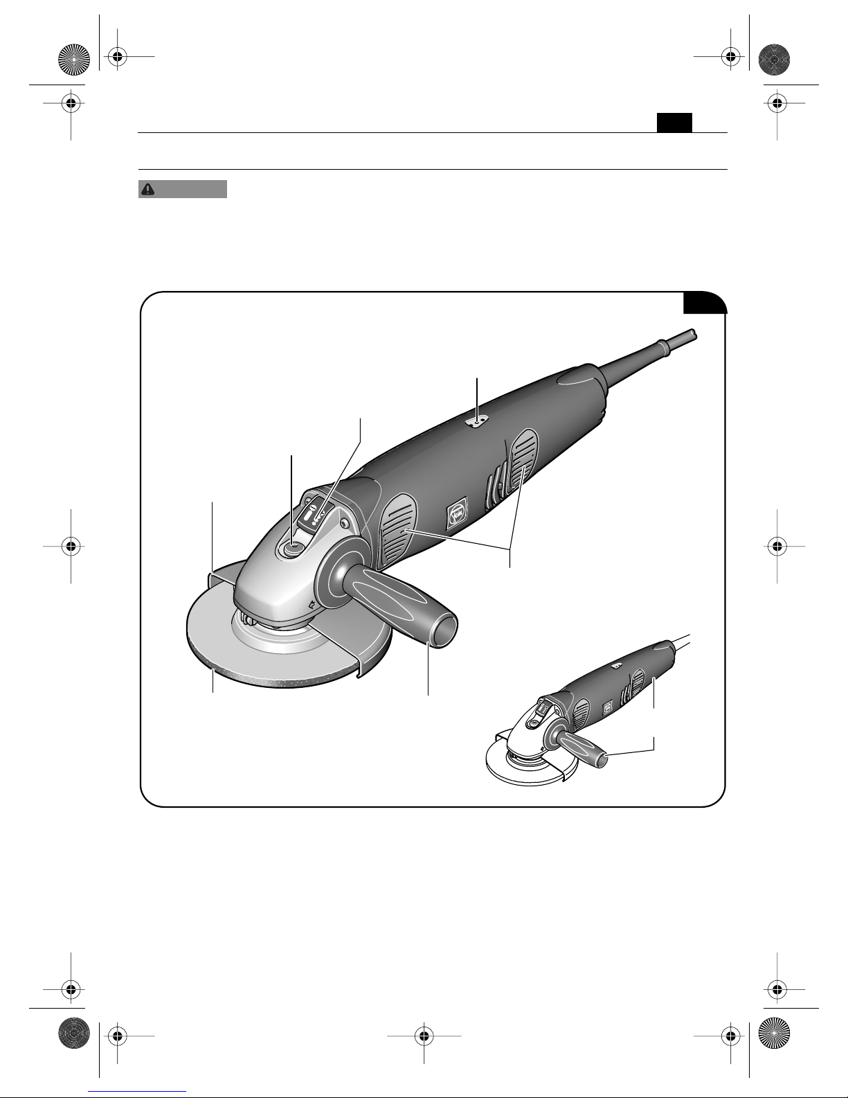
Technical description and specifications.
Before mounting or replacing application tools or accessories, pull the power
plug. This preventive safety measure rules out the danger of injuries through
accidental starting of the power tool.
Only part of the accessories described or shown in this instruction manual will be included
with your power tool.
WARNING
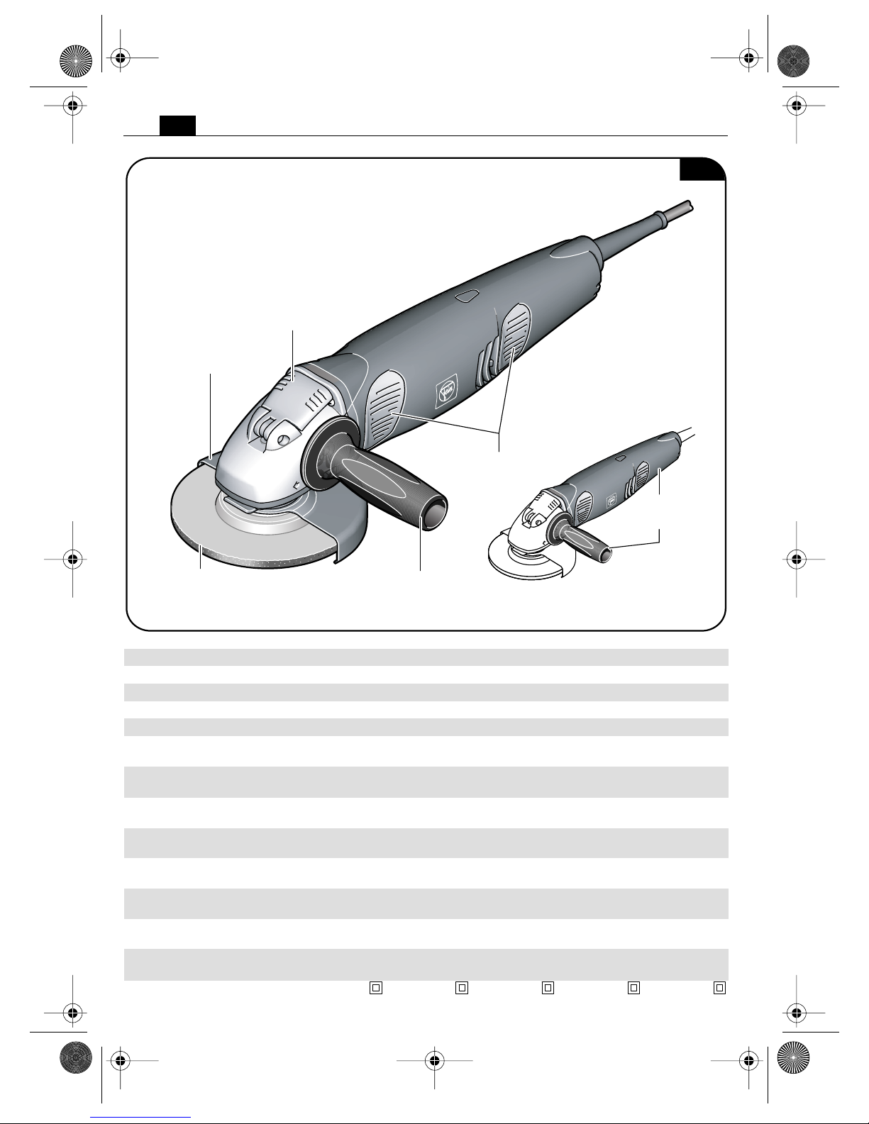
Grinding disc
Auxiliary handle
Fig. 1
Wheel guard
Locking button
WSG10-115T
WSG14-125T
WSG14-150T
WSG14-70ET
Speed regulation
button
(WSG14-70ET)
Speed display
(WSG14-70ET)
Pressing surface (4x)
Gripping surface
3 41 01 121 21 0.book Seite 13 Montag, 22. August 2011 1:11 13
14
en
WSS14-125T
Grinding disc
Auxiliary handle
Fig. 2
Wheel guard
Rapid-clamping lever
Pressing
surface (4x)
Gripping
surface
Type WSG10-115T WSG14-125T WSG14-150T WSG14-70ET WSS14-125T
Reference number 7 221 55 7 221 56 7 221 57 7 221 58 7 221 54
Power input 800 W 1200 W 1200 W 1200 W 1200 W
Output 550 W 750 W 750 W 750 W 750 W
Power supply type 1 ~ 1 ~ 1 ~ 1 ~ 1 ~
Rated speed 10000/min 10000/min 7000/min 2500–
7000/min
10000/min
max. diameter of grinding/cutting
disc
4 1/2 in
115 mm
5 in
125 mm
6 in
150 mm
5 in
125 mm
5 in
125 mm
Diameter of mounting hole 7/8 in
22.23 mm
7/8 in
22.23 mm
7/8 in
22.23 mm
7/8 in
22.23 mm
7/8 in
22.23 mm
Thickness of grinding/cutting disc 1/16 in–1/4 in
1–6 mm
1/16 in–1/4 in
1–6 mm
1/16 in–1/4 in
1–6 mm
1/16 in–1/4 in
1–6 mm
1/16 in–1/4 in
1–6 mm
max. diameter of backing pad 4 1/2 in
115 mm
4 1/2 in–5 in
115/125 mm
6 in
150 mm
5 in
125 mm
4 1/2 in–5 in
115/125 mm
Thread for clamping flange 5/8 in–
11 UNC
5/8 in–
11 UNC
5/8 in–
11 UNC
5/8 in–
11 UNC
–
Length of mounting thread 3/4 in
20 mm
3/4 in
20 mm
3/4 in
20 mm
3/4 in
20 mm
–
Weight according to
EPTA-Procedure 01/2003
4.4 lbs
(2.0 kg)
5.0 lbs
(2.3 kg)
5.3 lbs
(2.4 kg)
5.3 lbs
(2.4 kg)
5.3 lbs
(2.4 kg)
Class of protection II II II II II
3 41 01 121 21 0.book Seite 14 Montag, 22. August 2011 1:11 13
15
en
Assembly instructions.
Before mounting or replacing application tools or accessories, pull the power
plug. This preventive safety measure rules out the danger of injuries through
accidental starting of the power tool.
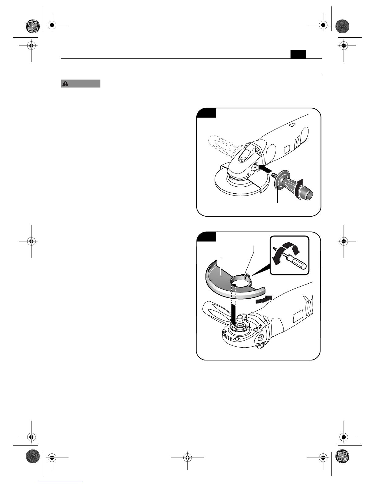
Mounting the auxiliary handle
(Figure 3).
➤ Screw the auxiliary handle tightly onto
the left or right side of the power tool,
depending on the working method.
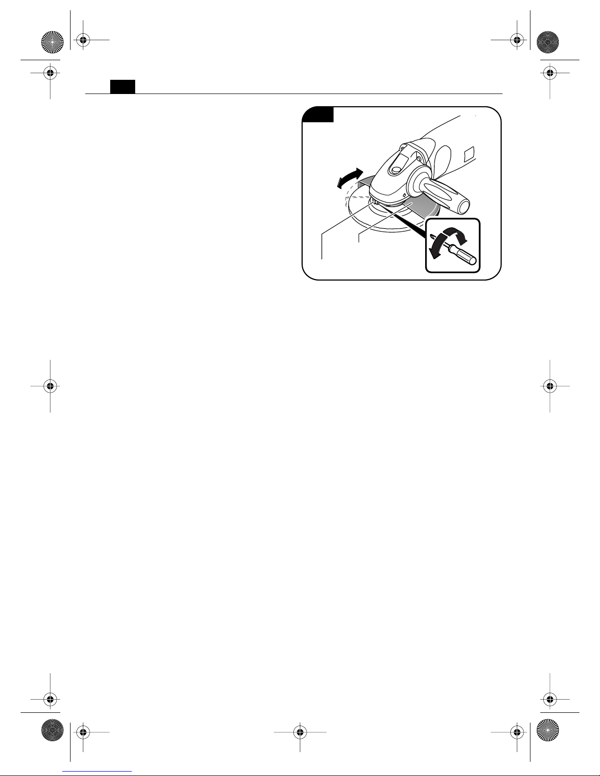
Mounting the guard (Figure 4)
WSG14-150T/WSG14-70ET.
➤ Loosen the tightening screw.
➤ Insert the clip of the wheel guard into
the groove on the power tool.
➤ Turn the wheel guard to the required
working position and clamp the wheel
guard using the tightening screw.
WARNING
Fig. 3
Auxiliary handle
Fig. 4
Wheel guard
Clamping screw
3 41 01 121 21 0.book Seite 15 Montag, 22. August 2011 1:11 13
16
en
Changing the tool.
Before mounting or replacing application tools or accessories, pull the power
plug. This preventive safety measure rules out the danger of injuries through
accidental starting of the power tool.
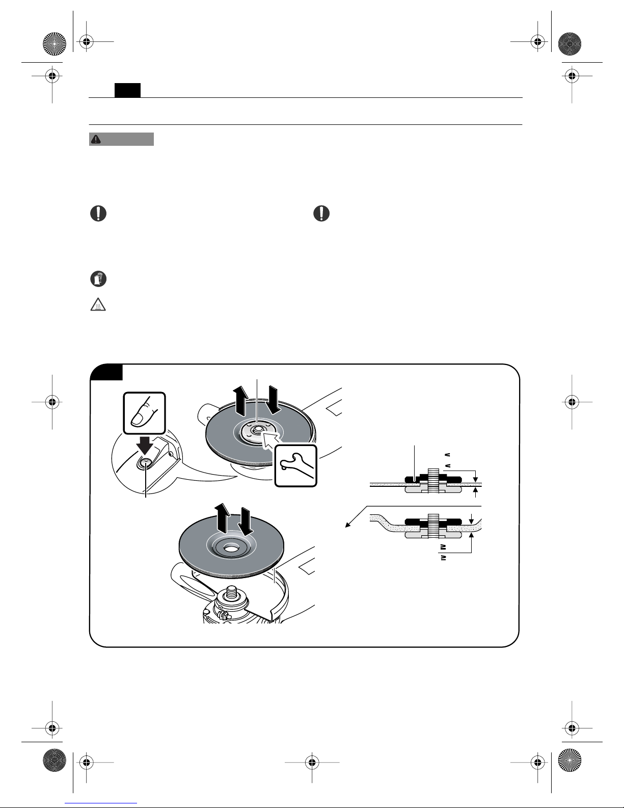
Mounting a grinding disc (Figure 5) WSG10-115T/WSG14-125T/WSG14-150T/
WSG14-70ET.
Only press the locking button when the
motor is not running.
➤ Press the locking button and keep it
pressed down. Undo the threaded flange
using the face spanner.
➤ Completely unscrew the threaded
flange.
➤ Change the used accessory or insert a
new one.
In so doing, make sure that the grinding
tool is centred properly between the
inner and threaded flange.
➤ Screw the threaded flange in again by
hand.
➤ Press the locking button and keep it
pressed down. Screw the threaded
flange tightly using the face spanner.
Note: Pay attention to the mounting direction
of the inner flange, which can vary depending
on the thickness of the grinding disc
(Figure 5).
WARNING
6 mm
1/4 in
6 mm
1/4 in
Fig. 5
Locking button
Threaded flange
Inner flange
3 41 01 121 21 0.book Seite 16 Montag, 22. August 2011 1:11 13
17
en
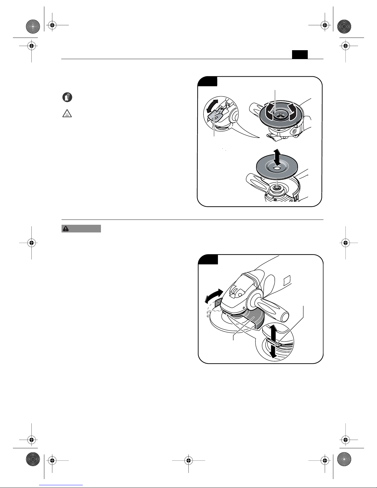
Mounting a grinding disc (Figure 6) WSS14-125T.
➤ Loosen the quick-clamping lever and
swivel it to the stop.
➤ Completely unscrew the clamping unit
by hand.
➤ Change the used accessory or insert a
new one.
➤ Turn the clamping unit in when the
rapid-clamping lever is open. Manually
tighten the clamping unit until a ratcheting noise starts.
➤ Swivel the quick-clamping lever back
until it engages.
Adjustments.
Before mounting or replacing application tools or accessories, pull the power
plug. This preventive safety measure rules out the danger of injuries through
accidental starting of the power tool.
Adjusting the guard (Figure 7)
WSS14-125T/WSG14-125T/
WSG10-115T.
➤ Unclamp the clamping lever.
➤ Swivel the guard into the required
working position.
➤ Notch in the clamping lever.
Fig. 6
Clamping unit
Rapid-clamping
lever
WARNING
Fig. 7
Wheel guard
Clamping lever
3 41 01 121 21 0.book Seite 17 Montag, 22. August 2011 1:11 13
18
en
Adjusting the guard (Figure 8)
WSG14-150T/WSG14-70ET.
➤ Loosen the tightening screw.
➤ Turn the wheel guard to the required
working position and clamp the wheel
guard using the tightening screw.
Fig. 8
Wheel guard
Clamping screw
3 41 01 121 21 0.book Seite 18 Montag, 22. August 2011 1:11 13
19
en
Working instructions.
Before mounting or replacing application tools or accessories, pull the power
plug. This preventive safety measure rules out the danger of injuries through
accidental starting of the power tool.
For each job, use only the FEIN application tool released and intended for the respective
application.
First check that the mains supply lead and mains plug are
not damaged.
Always hold the power tool
firmly. Otherwise, you could
lose control over the power tool.
WSG10T/WSG14T: Press the locking but-
ton only when the motor is stopped.
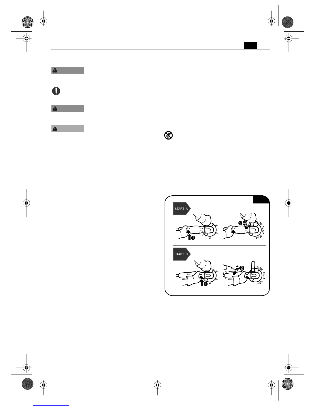
Starting (Figure 9).
After inserting the mains plug, the angle grinder can be started in any working position by
pressing the pressing surfaces twice in succession.
➤ Hold the angle grinder in the required
working position, either at the
back (START A) or front (START B);
lightly press at least one of the 4 pressing
surfaces, and keep it/them pressed.
Please note: The accessory begins to move
with short, low-power impulses. The angle
grinder thereby indicates that the first pressing surface has been activated.
For the working position holding the power
tool at the back (START A):
➤ Briefly press one of the front switch-
pads (close to the auxiliary handle) with
your thumb.
For the working position holding the power
tool at the front (START B):
➤ Briefly press one of the rear switch-
pads.
The angle grinder starts gently and rea-
ches its working speed after a short time.
Please note: The angle grinder does not start
up:
– when the switchpads at the front and rear
are pressed at the same time
– when the rapid-clamping lever is not tilted
back and engaged
– if one or more of the pressing surfaces is/
are pressed while the mains plug is inserted
WARNING
WARNING
CAUTION
➊
➋
➋
Fig. 9
3 41 01 121 21 0.book Seite 19 Montag, 22. August 2011 1:11 13
20
en
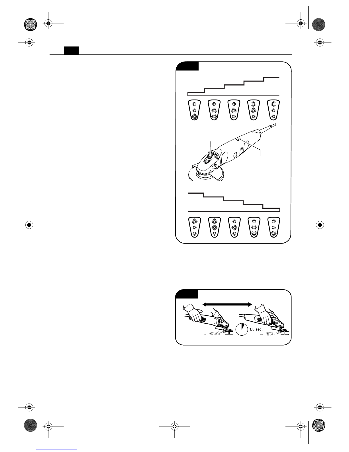
Setting the speed (Figure 10)
WSG14-70ET.
The speed can be set to different levels.
To increase the speed:
➤ Briefly press button.
Reducing the speed:
➤ Keep button pressed down.
The speed set is shown by the symbols on the
speed display.
The last speed setting used is stored in the
power tool after stopping the motor or after
pulling out the mains plug from the mains
socket.
➤ The speed can be preset when the
mains plug is inserted, also when the
motor is at a standstill.
Operation (Figure 11).
➤ Continuously press one of the 4
switchpads. The angle grinder is kept at
working speed.
Notes: The switchpads actuate easily in order
to prevent tense working postures. Changing
the working posture is possible at any time by
changing the switching position. The angle
grinder can be brought up to the working
speed again within 1.5 seconds by pressing
one of the 4 switchpads.
The self-start lock prevents the angle grinder
from automatically restarting again, even after
a brief interruption of the power supply, e.g.,
from a pulled mains plug.
2500/min
3000/min
5000/min
5900/min 7000/min
3500/min
4200/min
2500/min
3000/min
3500/min
5000/min
5900/min7000/min
4200/min
Fig. 10
Speed regulation
button
Speed display
Fig. 11
3 41 01 121 21 0.book Seite 20 Montag, 22. August 2011 1:11 13

21
en
Stopping (Figure 12).
➤ Let go of all the pressing surfaces. The
accessory begins to slow down.
Securing the work piece.
➤ Secure the workpiece adequately. A
workpiece that is not properly secured
can, for example, cause the accessory to
jam and kick back, fall and cause other
hazards.
Using the cut-off wheel guard (FIgure 13).
For cut-off grinding operations, always
work with the cut-off wheel guard
mounted.
➤ Before beginning to work, push the
cut-off wheel guard onto the already
mounted wheel guard for roughing.
Fig. 12
Fig. 13
Cut-off wheel
guard
Wheel guard
for roughing
3 41 01 121 21 0.book Seite 21 Montag, 22. August 2011 1:11 13
22
en
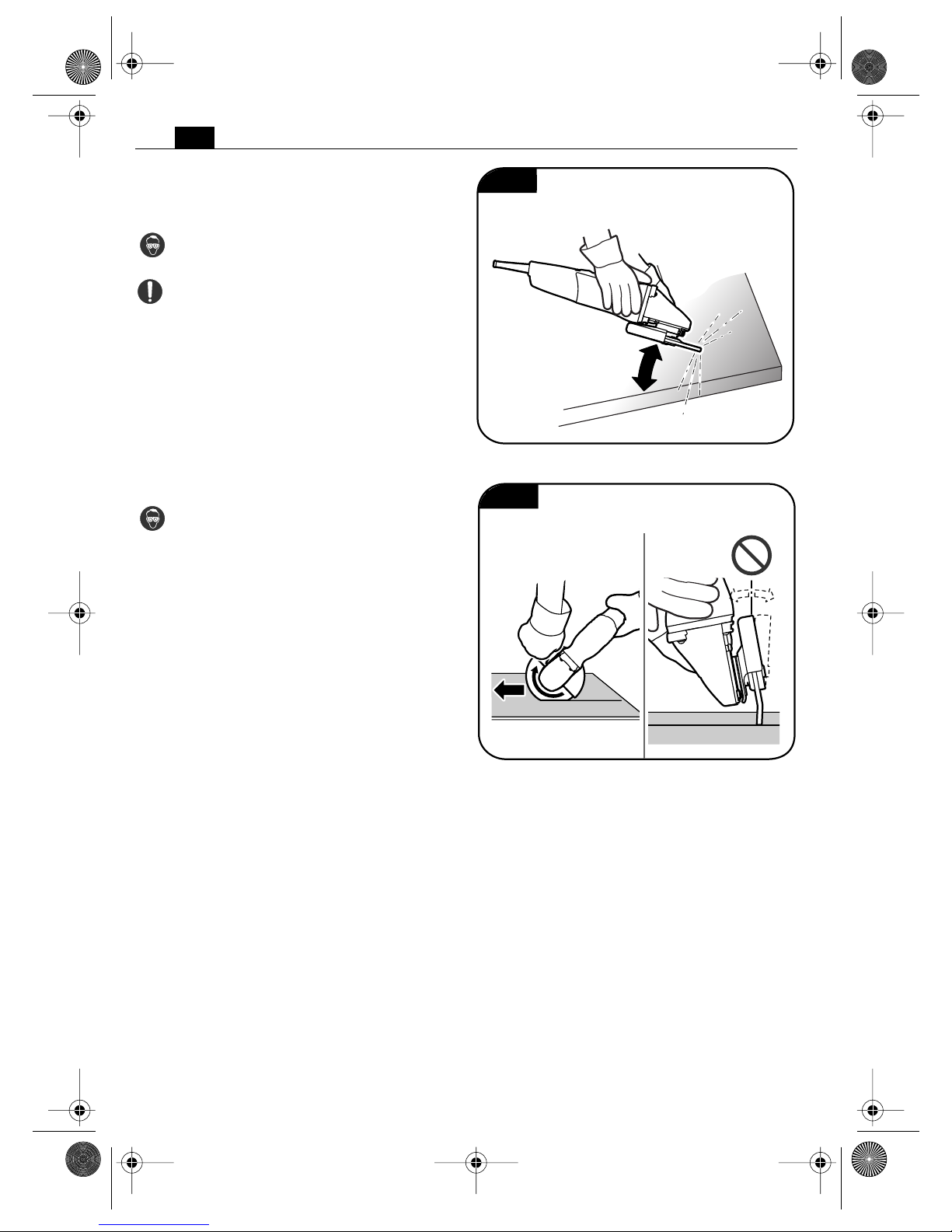
Grinding (Figure 14).
➤ Keep to an angle of tilt of 20 – 40°. In
this way you will obtain a good removal.
➤ Press the power tool on evenly and
move it over the surface.
➤ Do not allow the surface of the work-
piece to become too hot.
Cutting (Figure 15).
➤ Always work against the direction of
rotation so that the cutting wheel does
not jump out of the cut.
20°– 40°
Fig. 14
Fig. 15
3 41 01 121 21 0.book Seite 22 Montag, 22. August 2011 1:11 13
23
en
Maintenance.
Before mounting or replacing application tools or accessories, pull the power
plug. This preventive safety measure rules out the danger of injuries through
accidental starting of the power tool.
Service
Have maintenance carried out
only through qualified personnel. Incorrectly mounted leads and components
can cause serious injuries. Have the required
service carried out only through a FEIN customer service agent.
Cleaning
Prior to any cleaning or main-
tenance, disconnect the power
tool from the power supply in order to avoid
accidents.
When using in environments
with conductive dust in the air,
such as when working metals, this dust can
settle in the interior of the power tool. This can
impair the total insulation of the power tool.
Therefore, regularly blow out the interior of the
power tool from outside via the ventilation
openings with dry, oil-free compressed air;
always wear eye protection when doing this.
For additional protection, connect a residual
current device (RCD) on the line side.
Do not attempt to clean clogged or dirty
ventilation openings of the power tool
with pointed metal objects; use nonmetal tools or objects for this.
Do not use cleaning agents and solvents
that can cause damage to plastic parts.
These include: Gasoline, carbon-tetrachloride, chloric solvents, ammonia and domestic
cleaning agents that contain ammonia.
WSS14-125T: Unscrew the clamping unit by
hand to protect it from damage and dirt.
When the power tool’s power cable is
damaged, it must be replaced by a qualified person using a specially prepared power
cable, available from your FEIN customer
service agent.
If required, you can change the following parts
yourself: Application tools, auxiliary handle,
clamping unit or flanges, wheel guard
(WSG14-150T, WSG14-70ET).
Warranty and liability.
The warranty for the product is valid in
accordance with the legal regulations in the
country where it is marketed.
In addition, FEIN also provides a guarantee in
accordance with the FEIN manufacturer’s
guarantee. For further details on this, please
contact your specialist dealer, your national
FEIN representative, or the FEIN customer
service center.
Environmental protection,
disposal.
Packaging, worn out power tools and accessories should be sorted for environmentfriendly recycling. Further information can be
obtained from your specialist dealer.
WARNING
WARNING
WARNING
WARNING
3 41 01 121 21 0.book Seite 23 Montag, 22. August 2011 1:11 13
24
en
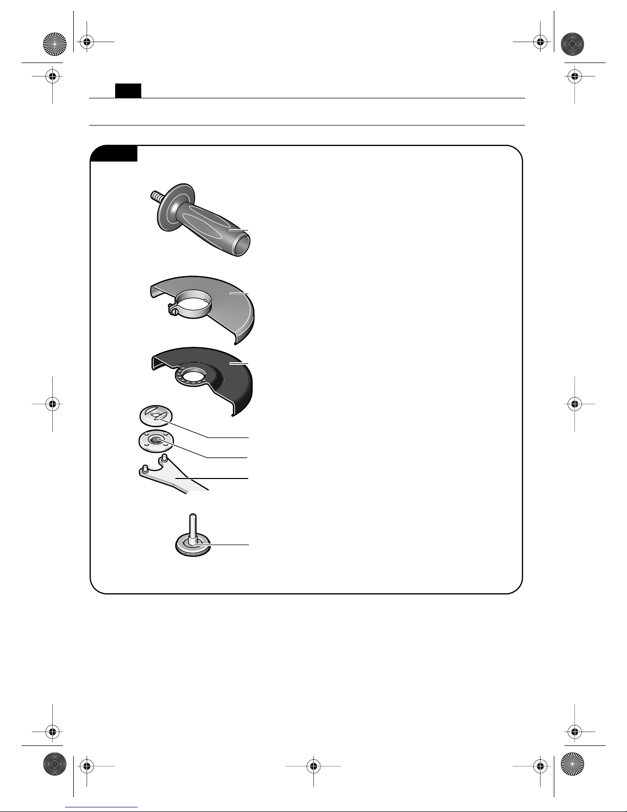
Provided Accessories (Figure 16).
WSG14-125T
WSG14-150T
WSG14-70ET
WSG10-115T
WSG14-150T
WSG14-70ET
WSS14-125T
WSG14-125T
WSG10-115T
WSS14-125T
Auxiliary handle
Fig. 16
Wheel guard
Wheel guard
Clamping unit
Threaded flange
Inner flange
Face spanner
3 41 01 121 21 0.book Seite 24 Montag, 22. August 2011 1:11 13
25
en
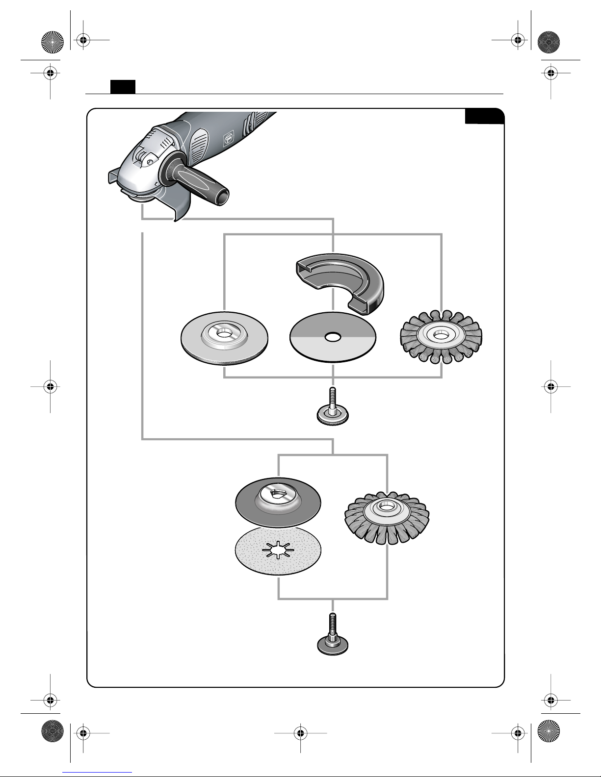
Selection of accessories (Figures 17–20).
The accessories must be intended for the power tool type.
A Grinding disc, flap disc
(use only with mounted wheel guard)
B Cut-off disc
(use only with mounted cut-off wheel guard)
C Steel wire brush, fleece backing pad
(use only with mounted wheel guard)
D Backing pad for fibre sanding sheets, fibre sanding sheets
(mount only with the provided backing-pad clamping unit; use only with mounted hand
guard or wheel guard)
E Steel tapered twist brush
(use only with mounted wheel guard)
F Backing pad with Velcro, Velcro sanding sheets, sanding fleece with Velcro attachment,
sponges
(use only with mounted hand guard)
G Steel cup brush, round twist brushes
(use only with mounted hand guard)
H Extraction nozzle for fibre sanding sheets
I Protective suction hood for grinding discs
3 41 01 121 21 0.book Seite 25 Montag, 22. August 2011 1:11 13
26
en
A
ED
BC
WSS14-125T
Fig. 17
3 41 01 121 21 0.book Seite 26 Montag, 22. August 2011 1:11 13
 Loading...