


RSs 636-1/2
To be handed to the workshop
~
Operating instructions
for the
double insulated and radio suppressed
Electric Nibblers type RSs 636-1, RSs
636-2
and type RSs 736-1 and RSs
736-2
(42
Volt)
1.
Technical
Data
Type
of
current:,...,
(AC
single
phase)
For sheet metal
up
to
Radius
of
Cu
tting
I
In
cisions
Net
Typ
e
sheet
stainle
ss
aluminium
3
)
sm
allest
sp
ee
d
I
Input
Outp
ut
Weig
ht
steel
')
steeJ2)
plastics
cu
rve
f~/
I
m/
per
Wa
tt
s Watts
SWG I
mm
SWG I
mm
SWG I
mm
lll.
I
I
RSs 636-1/2
18
1.3
22 I 0.8
14 2
3/4
RSs 736-
1/2
I
1
)
up
to
28.4 sh. ton/sq. in.
2
)
up to 42.5 sh. t on/sq. in.
3)
up
to 7.8 sh. ton/sq. in.
2.
Construction
This nibbler
is
an
electric
tool
of
Class
II
with
double insulation
and
in accordance
with
the
VDE
regulations 0740.
The
protective
insulation
is
additional
to
the normal insulation.
The
pole housing
is
insulated by
the
motor
housing
made
of
shockproof
Poly
amide
and
the electric parts
of the arma
ture
are protected by a separating in-
sulation against
the
dri
ve s
haft. The
machine is supplied with a two-
core cable wi
thout
earth
wire a
nd must
not
be ea
rth
ed. The high
voltage test is
made with the prescribed test v
olt
age of 4000 Volt
s.
The
machine
is
radio
-suppressed according
to
radio interference degree
N.
Type
RSs
736-1 , 736-2
(42
V)
is
of
the
same design
but
not double
insulated.
In
ord
er to prevent the ove
rbrid
ging
of the insulation no additional
marking
plates and
signs mu
st
be ri veted
or
screwed
on the housing.
We recomme
nd the u
se
of transfers onl y.
3.
Connection
and
Operation
Main v
olt
age must correspond
to the operating v
olt
age marked on
the rating plate. The tool can be plugged into plain
or
saf
ety sockets.
Switch must be in
the
»Off
<<
pos
ition
when
conn
ect
ing.
Type
RSs
636-1 is used to trim straig
ht
or
shaped sheet a
nd
corrugated
she
et
with
corrugations spaced
at
least 70 mm (2
3
/ 4
")
apart
. To cur
holes
or
openings
of any
kind, first drill a
pilot
hole of 18
-25
mm
dia.,
so
that
the anvil can be
introd~ced
.
Cutting dir
ection:
in
line
w
ith
motor axi
s.
Type RSs 636- 2 w
ith
anvil offset t
hrou
gh 90 °, is u
se
d for working
on
corrugated sheet w
ith
closely s
pac
ed corru gations. Cu
tti
ng direc-
tio
n:
at rig
ht angl
es
to mo
tor
axis.
BE 147/e
CX
5.72
Printed
in Germany
I mm
mm
I
20
.I
5.6
I
'
Capac
ity:
minute
mm
1.7 1800 280
15
0
I
I
Steel
sheet (drawn) max. 1.3 mm -
3
/o
•"
Stainl
ess
steel sheet max. 0.8 mm -1/sz"
Aluminium sheet max. 2
mm
-
5
fG
4"
Welding
seams
must
not
be
cut!
lbs I kg
3.5 1.6
No claims can be entertained for damage resulting fr
om
cutting sheett
of heavier
gauges
or
higher strength than thos
e sp
eci
fied here
or
work
with blunt bla
des
or
inadequate lubrication.
N
ever work
with
blunt
blades
and
inserts
U
se
of
blunt cutting edg
es
imposes an excessive load on the anvil
which is likely to fracture.
4.
Maint
enance
and
Lubrication
Before carrying
out any ma
inten
ance
work
alwa
ys reme
mber
to
pull
out
the
plug.
E
ver
y 300
duty
hours the tool should be cleaned thoroughly in
ord
er
to guarantee the safety given
by
the
protective insu
latio
n. For th
is
purpose carbon holders
and
insulated parts must
be
cleaned by means
of
a brush or
by
blowing out the tool
with dry pneumatic a
ir
or
a
hand
blower.
Aft
er checking carbon
brushes
for wear, make sure that they are
refi
tt
ed in their original place and
that th
ey m
ove
easily
in thei
r holder.
They sh
ou
ld be replaced
at
the latest
when
they have worn down to
7 mm (II<"). Please, only use original Fein
car
bon brus hes (Ord
er
Reference EZ 11-62).
After
fitting new
brushes, run
tool unloaded for
about
15
minutes to allow brush
es
to
bed in.
One pair
of
spare carbon brush
es
will be found in the
handle; pleas
e,
do
not
forget
to reord
er them in time.
In
order to preve
nt
accidents che
ck
cable
at
regular interval
s.
To
replace the cable un
sc
rew the screws (22) a
nd
(23
) a
nd
rem
ove
the
c
over
(21). Cla
mp
off cable from switch (14), unscr
ew screws (20)
at cable clamping bridge (19) and take
out
cabl
e.

66-
- --
-.
65-~
•
IIIJr-
=
I
64
1lLl.illlr
69
u
73
67~
111111-..
I
70--
71
..
68
--
76-~,
72
74
45
49 46
=\ \
n;;&
\
I
75
42
44
I
52
53 54 52
57
56
r
____
___..
-----
t I I L I
~
~
47
48
50
51
=
eo,
I
_____
_.
______
..
41
40
I
L
..
® _
«P
•
'f>}rt-r
~@\-
~@
.----,
..
I
r----
--------
-------- --------
-----J
1
,_-
__
11
33
•
,....
I
0
,
---
L~
•
..__a
·
-.
~
~
-ill"'
. =
§~8
..
-.
I J I I J - 5 I 1 I I I t . 1
55
33
31
32
30
.J..--4
26
11
9 8
7
6 J
r---
....
--
•
t
I
._
____
_
~
----
---------·
---------
------
1
b~"'-
·-
19
18
17
3
"-----
-~ - 2
10•~~~
13
1M
10
13
I
14
,,
~-~
---
----
''-
11
CJ'
~
A /
::
~o
---=-
~
./
--
------
--
....
~
16
22
I
21
I
23
0
z
Order
:>-
'-'
Reference
cY
...
"'
P-.
1-16,
MK
1-17-1
1
)
1
19-23
b 1
MK
1-17
1
2 SA 16-25 1
3
SA 16-28 1
4
SA 5-48 1
5
SR
3-M4x6
1
b 6
state
type
1
and
voltage
7
PT 6-M
3,5 2
8
.
SR
2-M3,5x50
2
9
JS
28-7
1
10
EZ
12-55-1
1
lOa
EZ 12-56-1
1
a
11
EZ
11-62 2
13
SR
3-M3,5x18 I
2
14
EZ
1-60
I
'
1
a
15
EZ
22-37
1
16
SR
3-M3,5x6 1
a
17
EZ
7-101 1
a 18
JS 13-7
1
19
PT
31-21 1
20
SR
3-M3,5x10
2
b
21
PT
27-28
1
22 SR6k-M3,5x8 1
23
SR
3-M3,5x32 1
b
26-32
state type
1
an
d v
olta
ge
b 30
ZR
4-42
1
31
SR
2-M3,5x6
3
32
PT
5d-M3,5 3
b
33
LK 16-35 2
40-54
GH 7-4-3
1
62-76
GH
7-5-3
' 1
40
LA 6-160
1
41
BF 1-4x18 1
42
PT
5d-M5
2
43
SR
33-M5x
35
I 2
44-54 LA 8-111-1
1
44
LA
8-111
1
1
)
state type and voltage
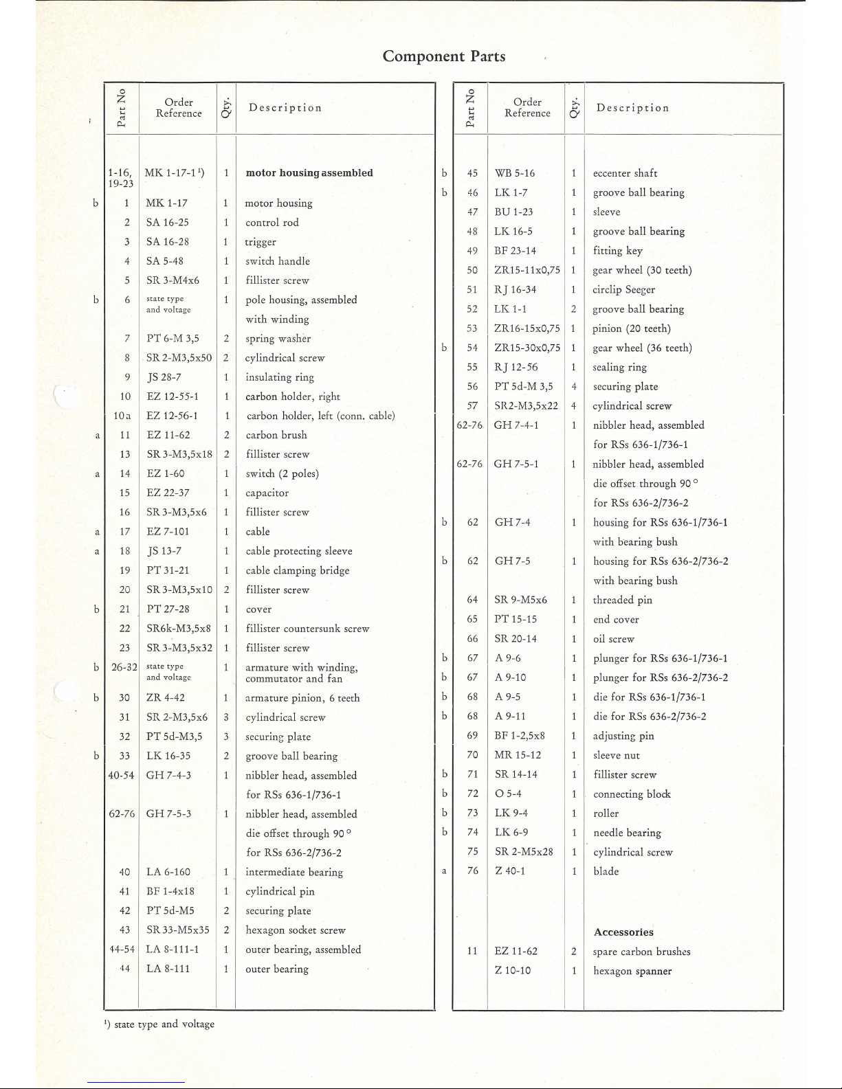
Component Parts
Description
motor
housing
assembled
motor
housing
control
rod
trigger
switch
handle
fillister screw
pole
housing, assembled
with
winding
SJ.?ring was
her
cy
lindrical
screw
insulating ring
carbon
holder,
right
carbon holder, left (conn. cable)
carbon
brush
fillister screw
switch (2 poles)
capacitor
fillister s
crew
cable
cable
protecting
sleeve
ca
ble clamping
brid
ge
fillister screw
cover
fillister countersunk screw
fillister screw
armature with windin
g,
c
ommutator
and
fan
armature
pinion,
6 teeth
cylindric
al screw
securing pl
ate
groove ball
bea
rin
g
nibbl
er hea
d,
asse
mbl
ed
for
RSs 636-1/736-1
nibbler
head,
assembled
die offset
through
90 °
for RSs 636-2/736-2
intermediate
bea
ring
cy
lindrical
pin
securing
plate
hexagon
socket screw
out
er bearing, assembled
out
er bea
ring
b
b
b
b
b
b
b
b
b
b
b
b
b
a
0
z
Order
..,
Reference
...
"'
P-.
45
WB 5-16
46
LK
1-7
47
BU
1-23
48
LK
16-5
49 BF 23-14
50
ZR
15-11x0,75
51
R]
16-34
52
LK
1-1
53
ZR16-15x0,75
54
ZR 15-30x0,75
55
RJ12-56
56
PT
5d-M
3,5
57 SR2-M3,5x22
62-76
GH
7-4-1
62-76
GH
7-5-1
62
GH7-4
62
GH
7-5
64
SR
9-M5x6
65
PT
15-15
66
SR
20-14
67 A 9-6
67 A
9-
10
68 A 9-5
68 A 9-11
69
BF 1-2,5x8
70 MR 15-12
71
SR
14-14
72
0 5-4
73
LK
9-4
74 LK 6-9
75
SR 2-M5x28
76
z 40-1
11
EZ 11-62
z 10-10
:>-
6
Description
I
1
eccenter
shaft
1 groove ball
bearing
1
sl
ee
ve
1
gr
oove
ball
bearing
1 fitti
ng
key
1
ge
ar
wheel (30 teeth)
1 circlip Seeger
2
groove ball
bearing
1 pini
on
(20 teeth)
1 gear wheel (36 teeth)
1 sealing
ring
4 securing
plate
4
cylin
drical
screw
1 nibbl
er
head,
assembled
I
for RSs 636-1/736-1
I
1
nibbler
head,
assembled
die offset
through
90 °
for RSs 636-2/736-2
1
housi
ng
for
RSs 636-1/736-1
with bearing
bush
1 housing
for
RSs 636-2/736-2
w
it
h be
aring
bush
1 threa
ded
pin
1 end
cover
1 oil s
crew
1
plung
er
for
RSs 636-1/736-1
I
1
plu
nger
for RSs 636-2/736-2
1 die f
or
RSs 636-1/736-1
1 die f
or
RSs 636-2/736-2
1 ad
just
ing
pin
1
sleeve
nut
1 fillister scr
ew
1
connecting block
1 roller
1
n
ee
dle
bearing
1 cyli
ndrical
screw
1
b
la
de
Accessories
2
spare
carbon
brush
~s
1
hexag
on
spanner

Blades
and
inserts should be sharpened
with
a fine honing stone. When
the
bright
cylindrical
part
of
the blade has been
ground
away, a new
blade
must
be fitted.
The
edge
of
the
cutter
insert must also be
sharp
at
all rimes; resharpen
only
the
top
face.
From
time to
tim
e,
apply
a few drops
of
oil
to
the
slot
in
the
anvil
to
lubricate the blade guides. Also lubricate
the
cutting edge
by
apply-
ing a
little
oil
with
a brush along the scribed line
on
the ·sheet. Slacken
screw (66), every day,
and
apply
a few drops
of
oil here, to lubricate
the slides
of
plunger (67), connecting linkage (72)
with
roller (73),
needle bearing (74)
and
ball bearing (46).
The
nibbler head being the
power
transmitting
element requires good
lubrication. The gear grease should be renewed
after
approx. 300
working
hours. Please,
only
use
our
special
FEIN
gear grease
Sst
1.
A mixing
of
this grease
with
other
greases endangers the greasing
capacities,
and
therefore also
usc
Sst 1 grease for rhe roller bearings in
the gear head.
quantity
order
reference
I
contents
·rype
I
I
oz
g oz
g
I Sst 1 for gears
1 0.53 1
15
MZ
60-3/Sst
1 I 3.2 I 90
No
claims can be
entertained
for
damage
due
to
negligent maintenance
or
inadequate
lubrication.
After
900
working
hours
the machine s
hould
be cleaned thoroughly.
For
this purpose the machine
is
dismantled as described in
paragraph
5
and
the
individual
parts
are
then cleaned.
The
ball
be~rings
(33)
are rinsed
in
clean solvent
and,
when
dry,
packed
with
our
special
grease Sst 1.
In
orda
to
prevent
overheating
of
the
bearings
at
high
speeds
the
space between
inner
and
outer ring
of
the bearing should
be filled
only
about
1
/a
with
grease.
5.
Dismantling
The
tool should only
be
taken
apart
by
an
expert, working m the
following sequence:
1. Unscrew screws (22, 23), then rake off handle cover (21 ).
2.
Loosen connection cable from switch (14)
and
draw
out
switch.
Clamp
off
motor
cable.
Unscrew screws (12),
take
out
carbon
holder
(10), remove screw
(16)
and draw
out
interference capacitor (15).
3.
Unscrew
two
hexagon socket screws ( 43)
and
remove
outer
bear-
ing ( 44 ), unscrew
four
cylindrical screws (57)
and
take
off
inter-
mediate bearing (40).
4.
Draw
out
armature
(26), unscrew three screws (31)
and
remove
armature
pinion (30).
5.
Draw
insulating ring (9)
out
of
motor housing (1), unscrew cylin-
drical screws (8)
and
take out
pole housing (6).
6.
Repair
and
Spare
Parts
We recommend
our
Fein Service Stations
to
carry
out
all
overh
aul
and
repair
work
quickly
and
expertly.
When
ordering
spare
parts,
please,
quote
model
and
serial
No
in
addition
to
order
reference
or
send
in
sample
part.
We
draw
your
attention
to
the need to
carry
out a high
voltage test
in accordance
with
your
local regulations (or
VDE
regulation 0740)
before
taking
a tool
into
service
after
any
repair
carried
out
by your
own
staff.
(
 Loading...