

(
To be handed to the workshop
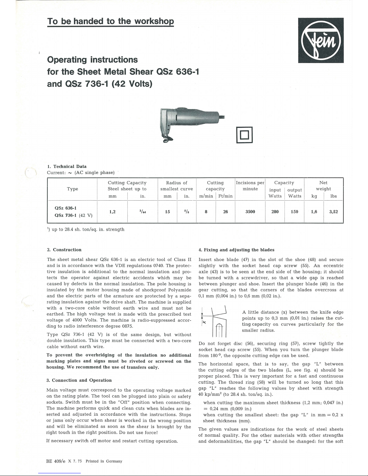
Operating instructions
for the
Sheet Metal Shear QSz 636-1
and
QSz 736-1
(42
Volts)
1.
Technical
Data
Current: ~ (AC
single
phase)
Cutting
Capacity
Radius
of
Type
Ste
el
sheet
up
to
smallest
curve
mm
I
in.
mm I in.
QSz
636-1
3
/64
>fa
1,2
15
QSz
736-1
(42 V)
1
)
up
to
28.4
sh.
ton/sq. in. strength
2.
Construction
The
sheet
metal
shear
QSz
636-1
is
an
electric -tool
of
Class
II
and
is
in
accordance
with
the
VDE
regulations
0740.
The
protec-
tive
insulation
is
additional
to
the
normal
insulation
and
pro-
tects
the ope
rator
against
electric
accidents
which
may
be
caused
by
defects
in
the
normal
insulation.
The
pole
housing
is
insulated
by
the
motor
housing
made
of
shockproof
Polyamide
and
the electric
parts
of
the
armature
are
protected
by a sepa-
rating
insulation
against
the
drive
shaft.
The
machine
is
supplied
with a two-core
cable
without
earth
wire
and
must
not
be
earthed.
The
high
voltage
test
is
made
with
the
prescrib
ed
test
voltage
of
4000
Volts.
The
machine
is
radio-suppressed
accor-
ding
to
radio
interference
degree
0875.
Type
QSz
736-1 (42 V)
is
of
the
same
design,
but without
double insu
lation.
This
type
must
be conne
cted
with a two-core
cable
without
earth
wire.
To
prevent
the
overbridging
of
the
insulation
no
additional
marking
plates
and
signs
must
be
riveted
or
screwed
on
the
housing.
We
recommend
the
use
of
transfers
only.
3.
Connection
and
Operation
Main
voltage
must
correspond
to
the
operating
voltage
marked
on
the
rating
plate.
The
tool
can
be
plugged
into
plain
or
safety
sockets.
Switch
must
be
in
the
"Off"
position
when
connecting.
The
machine
performs
quick
and
clean
cuts
when
blades
are
in-
serted
and
adjusted
in
accordance
with
the
instructions. Stops
or
jams ·only
occur
when
shear
is
worked
in
the
wrong
position
a
nd
will
be eliminated
as
soon
as
the
shear
is
brought
by the
right
tou
ch
in
the
right
position.
Do
not
use
force!
If
necessary
switch
off
motor
and
restart
cutting
operation.
BE 409/e X 7.
73
Printed
in
Germany
Cutting
Incisions
per
Capacity
Net
I
capacity
minute
i
nput I output
weight
m/min I Ft/min
Watts
Watts
kg
I
lbs
I
I
I
8
26
3500
280
150
1,6
3,52
4.
Fixing
and
adjusting
the
blades
Insert
shoe
blade
(47)
in the
slot
of
the
shoe
(48)
and
secure
slightly with
the
socket
head
cap
screw
(55).
An
eccentric
axle
(43)
is
to
be
seen
at
the
end
side
of
the
housing;
it
should
be
turn
ed
with a screwdriver, so
that a wide
gap
is
reached
between
plunger
and
shoe
. Insert
the
plunger bla
de
(46)
in
the
gear cutting,
so
that the
corne
rs
of
the
blades
overcross
at
0,1
mm (0,004 in.)
to
0,6
mm
(0,02 in.).
A
little
distance
(x)
between the
knife
edg
e
points
up
to
0,3
mm
(0,01
in.) raises
the
cut-
ting
capacity on
curves
particularly
for
the
smaller
radi
us.
Do
not
for
get
disc
(56).
securing
ring
(57).
screw
tightl
y t
he
socket
head
cap
screw
(55).
When
you
turn
the
plunger
blade
from
180 °,
the
opposite
cutting
edge
can
be
used
.
The
horizontal
space, that
is
to
say,
the
gap
"L"
between
the
cutting
edges
of the
two
blades
(L,
see
fig
. a)
should
be
proper
placed. This
is
very
important
for a fa
st
and
continuous
c
uttin
g.
The
thr
ead
ring
(58)
will
be
turned
so long
that
this
gap
"L"
reac
hes the fo
llo
wing values
by
sheet with
strength
40 kp/
mm2 (to 28.4
sh.
ton/sq.
in.).
when
cutting
the
maximum
sheet
thickness (1,2 mm; 0,047 in.)
= 0,24
mm
(0,009 in.)
when
cutt
ing
the
smallest
sheet:
the
gap
"L" in
mm
= 0,2 x
sheet thickness
(mm),
The giv
en
values
are
indications
for
the
work
of
steel
sheets
of
normal
quality. For
the
other
materials
with other
strengths
and
deformabilities,
the
gap
"L"
should
be
changed:
for
the
soft
50
49
4D
37 36 35 6 5 4 3 2 1
26
27
28
33
45------~~~~~
43
--
----~~~~ii~~::::::~~~IJ~~fl
42 - -
--!Lt----ll-----00
~
I
~
-
-
64
44
--
-~
52
~::±:-:71Y
A t·
I
,.
47
--
------v-
rt--
33
29
32
31
22 23
54
~56
53 .
..
57
-
55
-----
58
13
14
15
46 47 48
--+-
- -
-+-
H---+l-1--- · @ ) ' \ I
HI
p - . ' I
}#t(~·_j
9 8 7
10a
16
20
19
18
17
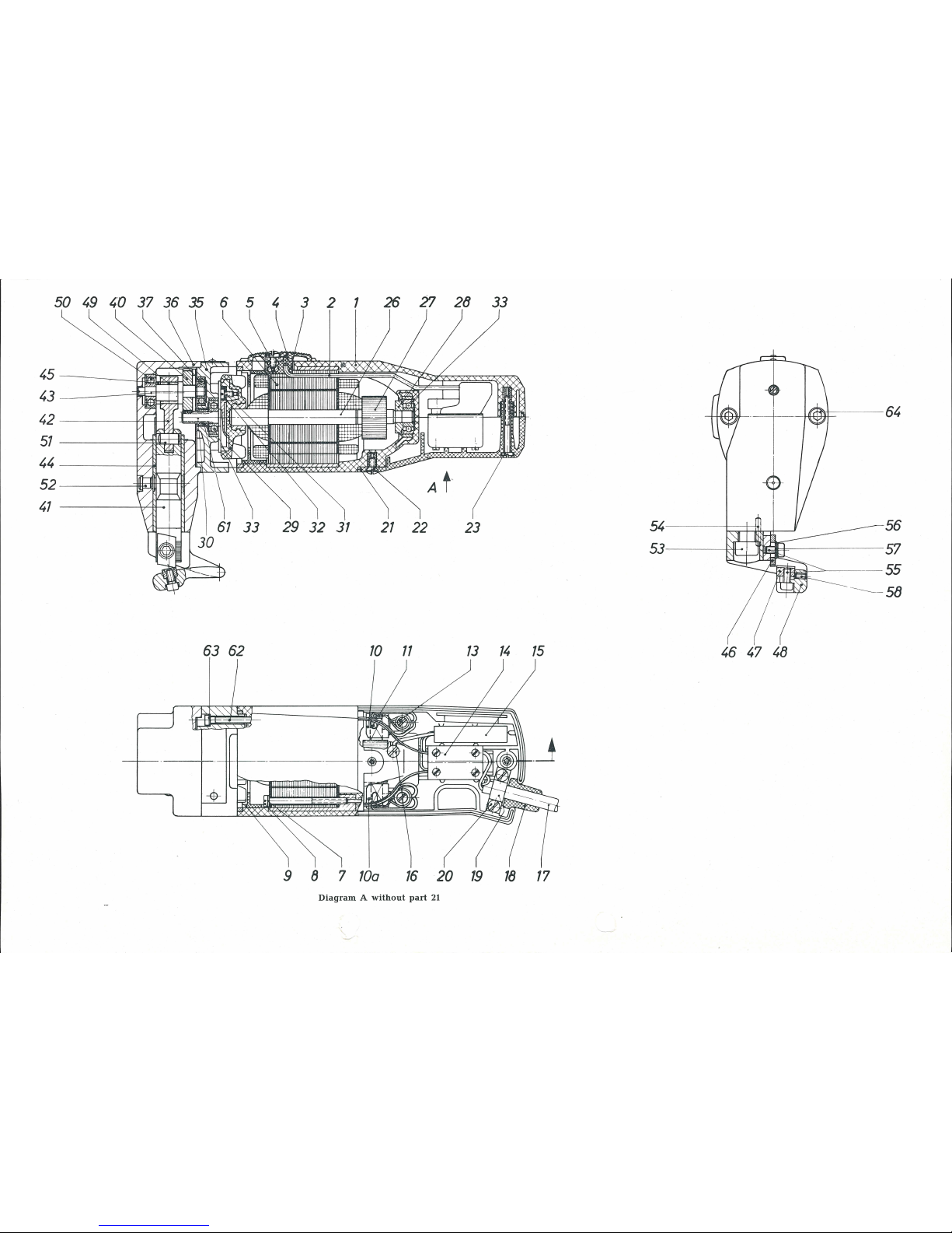
Diagram A without
part
21

Component Parts
Order
;...
Part
No.
a
Description
Reference
Order
;...
Part
No.
a
Description
Reference
I
1-16,
MK
1-17-1
1
)
1
motor
housing,
assembled
37
LK
1-1
1
grooved
ball
bearing
19-23
40
ZR15-11x0,75
1
gear
wheel,
30
teeth
1
MK
1-17 1
motor
housing
41
A 9-78
1
plunger
2
SA
16-25 1
control
rod
42
A 9-79
1
bolt
3
SA
16-28 1
trigger
43
WB
5-23
1
eccen
tric
axle
4
SA
5-48
1
switch
handle
44
BU
2-63
1
sl
eeve
5
SR
3-M4x6
1
fillister
head
screw
45
RJ
1-194
1
distance
ring
6
state
type
1
pole
housing, assembled
and
voltage
with
winding
7
PT
6-M3,5 2
spring
washer
8
SR2-M3,5x50
2
cylindrical
screw
9
JS
28-7
1
grease
retaining
ring
10 EZ 12-55-1
1
carbon
holder, right
10 a
EZ 12-56-1
1
carbon
holder,
left
(side
of
cable
connection)
11
EZ 11-62 2
carbon
brush
46
z 37-45
1
p
lu
nger
blade
47
z 37-46
1
shoe
blade
48
A
9-80
1
shoe
49
LK
6-50
1
needle
cage
50
LK 16-63
1
grooved
ball
bearing
51
LK 9-13
1
cylin
drical
roller
52
MZ
31-1
1
lub
ricating
nipple
53
SR35-M8x25
1
socket
head
cap
screw
13
SR
41-M3,5x18
2
fillister
head
screw
54
BF
1-3x16 2
cylindrical
pin
14
EZ 1-60
1
switch
(2
poles)
15 EZ 22-37 1
parallel
capacitor
16 SR 3-M3,5x6
1
fillister
head
screw
17
EZ 7-101
1
cable
with
plug
17 EZ 6-126 1
cable
without
plug
for
42
Volts
18
JS
13-7
1
cable
protecting
sleeve
19 I PT
31-21 1
clamping
bridge
20
SR 41-M3,5x10
2
fillister
head
screw
21
PT
27-28
1
motor
housing
cover
55
SR 35
-M4x8
2
socket
head
cap
screw
56
PT
1-M4
1
disc
57
PT 5d-M4
1
securing
ring
58
SR
10-M4x6 1
grub
screw
61
RJ
12-52
1
sealing
plate
62
SR2
-M
3,5x22
4
cylindrical
screw
63
PT
5d-M3,5 4
securing
ring
64
SR
33-M5x20
2
socket head
cap
screw
65
PT
5d-M5
2
securing
ring
(for
pos.
64)
22
SR6k-M3,5x8
1
fillister
head
countersunk
screw
23 SR3-M3,5
x32
1
fillister
head
screw
Accessories
26-32
state
type
1
armature
with
winding,
commutator
and
voltage
and
fan,
balanced
30
ZR 4-42
1
pinion, 6 teeth
31
SR2-M3,5x6
3
cylindrical
screw
32
PT
5d-M3,5
3
securing
plate
LE 1-2 1
gauge
for
sharpening
z 10-10
1
h
exagon socket
wrench
z 10-13
1
hexagon
socket
wrench
EZ 11-62 2
spare
carbon
brush
(in
the
moto
r h
ousing)
33 LK 16-35 2
grooved
ball
bearing
MZ
32-13
1
grease
gun
35
LA
6-160 1
intermediate
bearing
36-58
LA 8-1
52-1
1
outer
bearing,
assembled
Accessory
on
demand
36
LA
8-152 .
1
out
er bearing
I
I
BF 29- 147-1
I
I
1 I
guard, assembled
1
)
Please
state
voltage, when
ordering.

and
tough
materials
the
gap
"L"
must
be
reduced,
for
the
hard
and
brittle
materials,
it
should
be
enlarged
.
After
hi:lving
adjusted
the
gap
(L).
the
scre
w (55)
will
be
tightl
y
screwed,
the
screw
(58)
will
be
turned
aga
inst
the
shoe
blade
and
the
gap
"L"
once
more
controlled.
The
blades
should
be
taken
out
for
resharpening
by
loosing
the
screws
(55).
Do
not
lose
the
washers
(56, 57).
When
sharpening,
use
plenty
of
coolant
and
strictly
observe
the
prescrib
ed
cutting
angles
(fig.
b.
and
c.)!
They
are
easy
to
check
with
the
gauge,
which
is
supplied
free
of
charge
with
the
machine.
Their
application
is
illustrated
in
fig.
b.
and
c.
Fig. b
J
,-\/
\
1
I
I
..
L,
i
-$-
!
L .-·-·
-·-·-·.J
Never
work
with
blunt
blades!
Attention!
Do
not
cut
welding
seams!
/'\
.
( \
Fig.
c ·;, \
/ /
J:;:\
.//
\
//
,........·'
\ \
/
./·
\
_,/.)
\,
l=~
---
\....-
~
e
It
is
recommended
to
true
regularly
the cutting
edges
with
an
oil
stone.
No
claims
can
be
enter
tained
for
damage
due
to
work
with
too
thick
sheets
and
materials
and
to
work
with
inad
equate
or
blunt
blades.
5.
Maintenance
and
Lubrication
The machine
must
be
(according
to use)
greased
once
. a
day
at
the
grease
point
with a grease
gun (grease
Sst
1).
It
should
be
greased
when
the
machine
runs
in
no
load,
till
clean
grease
goes
out
at
the
plunger.
Before
carrying
out
any
maintenance
work,
always
remember
to
pull
out
the
plug.
After
300
working
hours
clean
cool
air
openings
at
the
motor
housing.
Blow
out
the
motor
with
dry
pneumatic
air.
Renew
gear
grease. For
this
purpose
take
out
shear
head
according
to
§ 6 (4).
Only
use
Fein spec
ial
grease
Sst
1.
This
grease
must
not
be
mixed
with
other
greases.
Quantity
of
grease:
13 g.
Order
Reference
for a tube
with
90 g:
MZ
60-3/Sst
1.
After
900
working
hours
take
apart
the
machine
accord
ing
to
§ 6
and
clean
thoroughly.
Clean
parts
of
the
gearing and ball
bearings
in
clean
solvent
and
pack
with
fresh
grease
Sst
1.
The
space
between
inner and
outer
ring
is
to
be
filled
one
third
with
grease
in
order
to
prevent
overheating
of
the
bearings.
Clean
electric
parts
only
dry.
For
checking the
carbon
brushes, the
carbon
holders
(10, 10 a)
can
be
taken
out
after
unscrewing the
screws
(13).
Make
sure
that
the
carbon
brushes
are
refitted
in their
original
place
and
th
at
they
move
easily
in
their
holder.
They
should
be
replaced
at
the
latest,
when they have
worn
down
to 7 mm
('// ').
Please
only
use
original
Fein
carbon
brushes
(Order
Reference
EZ 11-
62).
After
fitting
new
brushe
s,
run
tool
unloaded
for
about
15
minutes
to
allow
brushes
to
bed
in.
One
pair
of
carbon
brushes
will
be
found
in
the
motor
housing;
please, do
not
forget
to
reorder
them
in
time.
In
order
to
prevent
accidents,
check
cable
at
regular inter
val
s.
To
replace
the
cable,
unscrew
the
screws
(22)
and
(23)
and
re
move
the
cove
r (21).
Clamp
off
cable
from
switch
(14),
unscr
ew
screws
(20)
at
cable
clamping
bridge
(19)
and
take
out
cable.
No
claims
can
be
entertained
for
damage
due
to
negligen
t
maintenance
and
inadequate
lubricatio
n.
6.
Dismantling
The
machine
must
only
be
tak
en
apart
by
an
expert,
working
in
the
following
sequence:
1.
Unscrew
screws (22)
and
(23)
and
remove
motor
housing
cover
(21).
2.
Clamp
off
connections
to
pole
housing
(6).
capacitor
(15)
and
cable
(17)
at
swit
ch
(14)
and
take
out
switch.
Unscrew
screw
(16)
and
remove
capacitor
(15)
.
3.
Remove
screws
(13),
then
take
out
carbon
hold
ers
(10, 10 a).
4.
Remove
screws
(64),
and
take
off
shear
head.
5.
Unscrew
screws
(62)
and
remove interme
diate
bearing
(35).
6.
Draw
out
pinio
n (26).
In
case
of the
damage
of
the
pinion,
unscrew 3 screws
(31)
and
remove
armature
pinion
(30).
7.
Draw
grease retain
ing
ring
(9)
out
of
the
motor housing (1),
loos
en cylindrical
screws
(8).
and
take
out
pole
housing
(6)
.
8.
Dismantle
eccentric
axle
(43).
9.
Remove
shoe
and
take
out
plunger
(41).
Re-assemble
in
reverse
sequence.
Attention!
Hits
and
blows
on
the
fan
wheel
affect
the
good
ru
nning
conditions
of
the
armature
and
should
be
avoided
.
7.
Repair
and
Spare
Parts
We
recommend
our
Fein
Service Stations
to
carry
out
all
over-
haul
and
repair
work
quickly and
expertly
.
When
ordering
spare
parts,
please, quo
te
Order
Reference
or
send
in
sample
part, stating
the
type
of
the machine.
We
draw your
attention
to the n
eed
to
carry
out a high
voltage
t
est
in
accordance
with
your
local
regulations
(or
VDE
reg
ula-
tion
0740)
before
taking a tool into
service
aft
er
any
repair
carried
out
by
your
own
staff.
 Loading...